Page 4021 of 4378

Deactivate the system means to perform the deactivation procedure. Refer to Deactivation Procedure
in this section.
Prove Out the System
Prove out the system means to turn the ignition switch from the OFF to the RUN position and visually
monitor the air bag indicator with the air bag modules installed. Refer to Prove Out Procedure in this
section.
Reactivate the System
Reactivate the system means to perform the reactivation procedure. Refer to Reactivation Procedure
in this section.
Reconnect the System
Reconnect the system means to reconnect all system components. Refer to Air Bag System
Reconnect Checklist in this section.
Install a New Component
Install a new component means to remove the existing component and install a new authorized part
obtained from Ford Customer Service Division.
Verify the System
Verify the system means to prove out the system with restraint system diagnostic tools for the air bag
modules in place of components.
Air Bag System Reconnect Checklist
The checklist below should be completed following diagnosis or repair of any air bag system concern.
1. Is the connector at the base of the steering column connected?
2. Are the air bag modules connected?
3. Is the restraints control module (RCM) connected?
4. Is the vehicle battery connected? �K�l�j . 5 �b�a
62003 Mustang Workshop Manual
18. 11. 2011file:///C:/Ford/2000 - 2004/tsocache/SHEF_5108/S3B~us~en~ ...
Page 4074 of 4378

GENERAL PROCEDURES
Inspection and Repair After a Supplemental Restraint
System (SRS) Deployment
WARNING: If the supplemental restraint system (SRS) is being serviced, the system must
be deactivated and restraint system diagnostic tools must be installed. Refer to Air Bag Supplemental Restraint System (SRS) in this section.
The air bag restraint system diagnostic tools must be removed and the air bag modules
reconnected when the system is reactivated to avoid non- deployment in a collision, resulting in
possible personal injury.
NOTE: Diagnostics or repairs are not to be performed on a seat equipped with a seat side air bag with
the seat in the vehicle. Prior to attempting to diagnose or repair a seat concern when equipped with a
seat side air bag, the seat must be removed from the vehicle and the restraint system diagnostic tools
must be installed in the seat side air bag electrical connectors. The restraint system diagnostic
tools must be removed prior to operating the vehicle over the road.
NOTE: After diagnosing or repairing a SRS the restraint system diagnostic tools must be removed
before operating the vehicle over the road.
NOTE: After diagnosing or repairing a seat system the restraint system diagnostic tools must be
removed before operating the vehicle over the road.
NOTE: The SRS must be fully operational and free of faults before releasing the vehicle to the
customer.
1. When any deployable device (driver air bag, passenger air bag, seat side air bag, safety belt pretensioner, etc.) or combination of devices are deployed and/or the RCM has the DTC B1231
(Crash Data Memory Full) in memory, the repair of the vehicle's supplemental restraint system
(SRS) is to include the removal of all deployed devices and installation of new deployable
devices, the removal and installation of new impact sensors, and the removal and installation of
a new RCM.
2. When any damage to the impact sensor mounting points or mounting hardware has occurred, repair or install new mounting points and mounting hardware as needed.
3. When the driver air bag module has deployed a new clockspring must be installed.
4. Inspect the entire vehicle for damage, including the following components: �zsteering column.
�z instrument panel knee bolsters and mounting points.
�z instrument panel braces and brackets.
�z instrument panel and mounting points.
�z seats and seat mounting points.
�z safety belts, safety belt buckles, and safety belt retractors. For additional information,
refer to Section 501 - 20A .
�z supplemental restraint system (SRS) wiring, wiring harnesses, and connectors.
5. After carrying out the review and inspection of the entire vehicle for damage, repair or install new components as needed.
SECTION 501-
20B: Supplemental Restraint System 2003 Mustang Workshop Manual �K�l�j . 1 �b�a
22003 Mustang Workshop Manual
18. 11. 2011file:///C:/Ford/2000 - 2004/tsocache/SHEF_5108/S3B~us~en~ ...
Page 4086 of 4378

NOTE:
If a seat equipped with a seat mounted side air bag and/or a safety belt pretensioner (if
equipped) system is being serviced, the air bag system must be deactivated.
NOTE: Restraint system diagnostic tools MUST be installed under the seats in the seat side air bag (if
equipped) and safety belt pretensioner (if equipped) to floor connectors.
NOTE: Diagnostics or repairs are not to be performed on a seat equipped with a seat side air bag with
the seat in the vehicle. Prior to attempting to diagnose or repair a seat concern when equipped with a
seat side air bag, the seat must be removed from the vehicle and the restraint system diagnostic tools
must be installed in the seat side air bag electrical connectors. The restraint system diagnostic
tools must be removed prior to operating the vehicle over the road.
NOTE: After diagnosing or repairing an SRS, the restraint system diagnostic tools must be
removed before operating the vehicle over the road.
NOTE: After diagnosing or repairing a seat system, the restraint system diagnostic tools must be
removed before operating the vehicle over the road.
NOTE: The SRS must be fully operational and free of faults before releasing the vehicle to the
customer.
1. WARNING: To avoid accidental deployment and possible personal injury, the
backup power supply must be depleted before repairing or replacing any front or side air
bag supplemental restraint system (SRS) components and before servicing, replacing,
adjusting or striking components near the front or side air bag sensors, such as doors,
instrument panel, console, door latches, strikers, seats and hood latches.
Please refer to the appropriate vehicle shop manual to determine location of the front air
bag sensors.
The side air bag sensors are located at or near the base of the B- pillar.
To deplete the backup power supply energy, disconnect the battery ground cable and
wait at least one minute. Be sure to disconnect auxiliary batteries and power supplies (if
equipped).
Disconnect the battery ground cable and wait at least one minute. For additional information,
refer to Section 414 - 01 .
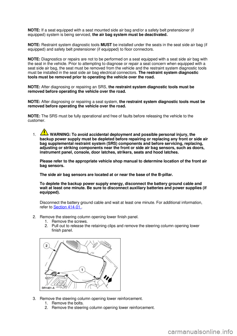
2. Remove the steering column opening lower finish panel. 1. Remove the screws.
2. Pull out to release the retaining clips and remove the steering column opening lower finish panel.
3. Remove the steering column opening lower reinforcement. 1. Remove the bolts.
2. Remove the steering column opening lower reinforcement. �K�l�j . 2 �b�a
72003 Mustang Workshop Manual
18. 11. 2011file:///C:/Ford/2000 - 2004/tsocache/SHEF_5108/S3B~us~en~ ...
Page 4087 of 4378
4. Pushing in on the release tab, disconnect the clockspring electrical connector at the base of the
steering column.
5. Attach the restraint system diagnostic tool to the vehicle harness side of the clockspring electrical connector.
6. Open the glove compartment, push in on the tabs and open the glove compartment door to its fullest extent.
7. Remove the right hand A/C register duct. �K�l�j . 3 �b�a
72003 Mustang Workshop Manual
18. 11. 2011file:///C:/Ford/2000 - 2004/tsocache/SHEF_5108/S3B~us~en~ ...
Page 4089 of 4378
3. Connect the passenger air bag module electrical connector.
4. Install the right hand A/C register duct.
�zConnect the A/C duct at the air plenum.
�z Install the duct at the A/C register and install the two screws.
5. Close the glove compartment.
6. Remove the restraint system diagnostic tool from the clockspring electrical connector.
7. Connect the clockspring electrical connector at the base of the steering column. �K�l�j . 5 �b�a
72003 Mustang Workshop Manual
18. 11. 2011file:///C:/Ford/2000 - 2004/tsocache/SHEF_5108/S3B~us~en~ ...
Page 4090 of 4378

8. Install the steering column opening lower reinforcement.
1. Position the steering column opening lower reinforcement.
2. Install the bolts.
9. Install the steering column opening lower finish panel. 1. Align the steering column opening lower finish panel and push in, seating the retaining clips.
2. Install the screws.
10. Connect the battery ground cable. For additional information, refer to Section 414 - 01 .
11. WARNING: The restraint system diagnostic tool is for restraint system service only.
Remove from vehicle prior to road use. Failure to remove could result in injury and
possible violation of vehicle safety standards.
With all the restraint system diagnostic tools removed, prove out the supplemental restraint
system (SRS). For additional information, refer to Air Bag Supplemental Restraint System (SRS) in the Diagnosis and Testing portion of this section. �K�l�j . 6 �b�a
72003 Mustang Workshop Manual
18. 11. 2011file:///C:/Ford/2000 - 2004/tsocache/SHEF_5108/S3B~us~en~ ...
Page 4103 of 4378

Please refer to the appropriate vehicle shop manual to determine location of the
front air bag sensors.
The side air bag sensors are located at or near the base of the B-
pillar.
To deplete the backup power supply energy, disconnect the battery ground cable
and wait at least one minute. Be sure to disconnect auxiliary batteries and power
supplies (if equipped).
Disconnect the battery ground cable (14301) and wait at least one minute. For additional
information, refer to Section 414 - 01 .
2. WARNING: To reduce the risk of serious personal injury, read and follow all
warnings, cautions, notes, and instructions in the supplemental restraint system
(SRS) deactivation/reactivation procedure.
Deactivate the supplemental restraint system (SRS). For additional information, refer to
Supplemental Restraint System (SRS) Deactivation and Reactivation in the General
Procedures portion of this section.
2. Remove the two steering wheel plugs.
3. Remove the two driver air bag module retaining bolts (one shown).
4. Remove the driver air bag module. 1. Disconnect the driver air bag module electrical connector.
2. Remove the driver air bag module. �K�l�j . 2 �b�a
62003 Mustang Workshop Manual
18. 11. 2011file:///C:/Ford/2000 - 2004/tsocache/SHEF_5108/S3B~us~en~ ...
Page 4104 of 4378
5. Remove the restraint system diagnostic tool from the vehicle harness side of the clockspring
electrical connector at the base of the steering column.
6. Connect the clockspring electrical connector at the base of the steering column.
7. Attach the restraint system diagnostic tool to the clockspring electrical connector at the top of the steering column.
8. Connect the battery ground cable. For additional information, refer to Section 414 - 01 . �K�l�j . 3 �b�a
62003 Mustang Workshop Manual
18. 11. 2011file:///C:/Ford/2000 - 2004/tsocache/SHEF_5108/S3B~us~en~ ...