2003 DODGE RAM automatic transmission fluid
[x] Cancel search: automatic transmission fluidPage 2043 of 2895
(6) Remove funnel, insert dipstick and check fluid
level. If level is low,add fluid to bring level to
MIN mark on dipstick.Check to see if the oil level
is equal on both sides of the dipstick. If one side is
noticably higher than the other, the dipstick has
picked up some oil from the dipstick tube. Allow the
oil to drain down the dipstick tube and re-check.
(7) Drive vehicle until transmission fluid is at nor-
mal operating temperature.
(8) With the engine running at curb idle speed, the
gear selector in NEUTRAL, and the parking brake
applied, check the transmission fluid level.
CAUTION: Do not overfill transmission, fluid foam-
ing and shifting problems can result.
(9) Add fluid to bring level up to MAX arrow
mark.
When fluid level is correct, shut engine off, release
park brake, remove funnel, and install dipstick in fill
tube.
FRONT CLUTCH
DESCRIPTION
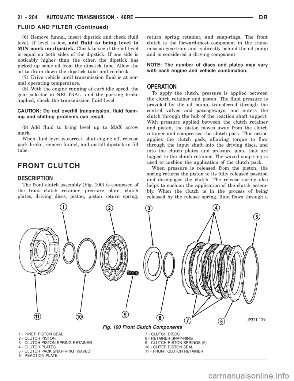
The front clutch assembly (Fig. 100) is composed of
the front clutch retainer, pressure plate, clutch
plates, driving discs, piston, piston return spring,return spring retainer, and snap-rings. The front
clutch is the forward-most component in the trans-
mission geartrain and is directly behind the oil pump
and is considered a driving component.
NOTE: The number of discs and plates may vary
with each engine and vehicle combination.
OPERATION
To apply the clutch, pressure is applied between
the clutch retainer and piston. The fluid pressure is
provided by the oil pump, transferred through the
control valves and passageways, and enters the
clutch through the hub of the reaction shaft support.
With pressure applied between the clutch retainer
and piston, the piston moves away from the clutch
retainer and compresses the clutch pack. This action
applies the clutch pack, allowing torque to flow
through the input shaft into the driving discs, and
into the clutch plates and pressure plate that are
lugged to the clutch retainer. The waved snap-ring is
used to cushion the application of the clutch pack.
When pressure is released from the piston, the
spring returns the piston to its fully released position
and disengages the clutch. The release spring also
helps to cushion the application of the clutch assem-
bly. When the clutch is in the process of being
released by the release spring, fluid flows through a
Fig. 100 Front Clutch Components
1 - INNER PISTON SEAL 7 - CLUTCH DISCS
2 - CLUTCH PISTON 8 - RETAINER SNAP-RING
3 - CLUTCH PISTON SPRING RETAINER 9 - CLUTCH PISTON SPRINGS (9)
4 - CLUTCH PLATES 10 - OUTER PISTON SEAL
5 - CLUTCH PACK SNAP-RING (WAVED) 11 - FRONT CLUTCH RETAINER
6 - REACTION PLATE
21 - 204 AUTOMATIC TRANSMISSION - 46REDR
FLUID AND FILTER (Continued)
Page 2044 of 2895
vent and one-way ball-check-valve located in the
clutch retainer. The check-valve is needed to elimi-
nate the possibility of plate drag caused by centrifu-
gal force acting on the residual fluid trapped in the
clutch piston retainer.
DISASSEMBLY
(1) Remove the waved snap-ring, reaction plate,
clutch plates, and clutch discs.
(2) Compress clutch piston retainer and piston
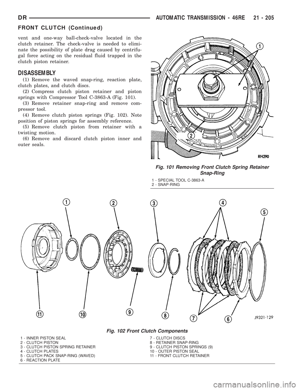
springs with Compressor Tool C-3863-A (Fig. 101).
(3) Remove retainer snap-ring and remove com-
pressor tool.
(4) Remove clutch piston springs (Fig. 102). Note
position of piston springs for assembly reference.
(5) Remove clutch piston from retainer with a
twisting motion.
(6) Remove and discard clutch piston inner and
outer seals.
Fig. 101 Removing Front Clutch Spring Retainer
Snap-Ring
1 - SPECIAL TOOL C-3863-A
2 - SNAP-RING
Fig. 102 Front Clutch Components
1 - INNER PISTON SEAL 7 - CLUTCH DISCS
2 - CLUTCH PISTON 8 - RETAINER SNAP-RING
3 - CLUTCH PISTON SPRING RETAINER 9 - CLUTCH PISTON SPRINGS (9)
4 - CLUTCH PLATES 10 - OUTER PISTON SEAL
5 - CLUTCH PACK SNAP-RING (WAVED) 11 - FRONT CLUTCH RETAINER
6 - REACTION PLATE
DRAUTOMATIC TRANSMISSION - 46RE 21 - 205
FRONT CLUTCH (Continued)
Page 2045 of 2895
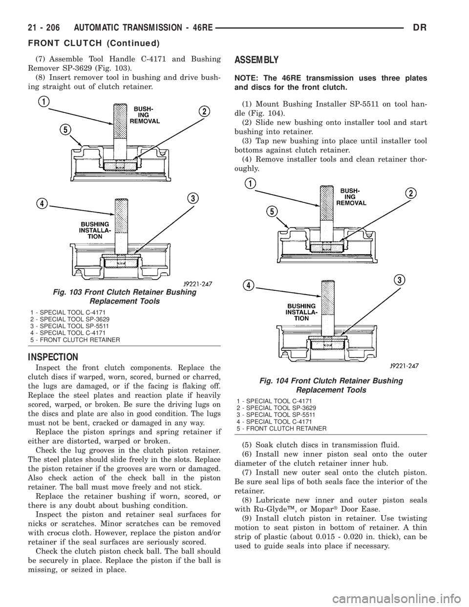
(7) Assemble Tool Handle C-4171 and Bushing
Remover SP-3629 (Fig. 103).
(8) Insert remover tool in bushing and drive bush-
ing straight out of clutch retainer.
INSPECTION
Inspect the front clutch components. Replace the
clutch discs if warped, worn, scored, burned or charred,
the lugs are damaged, or if the facing is flaking off.
Replace the steel plates and reaction plate if heavily
scored, warped, or broken. Be sure the driving lugs on
the discs and plate are also in good condition. The lugs
must not be bent, cracked or damaged in any way.
Replace the piston springs and spring retainer if
either are distorted, warped or broken.
Check the lug grooves in the clutch piston retainer.
The steel plates should slide freely in the slots. Replace
the piston retainer if the grooves are worn or damaged.
Also check action of the check ball in the piston
retainer. The ball must move freely and not stick.
Replace the retainer bushing if worn, scored, or
there is any doubt about bushing condition.
Inspect the piston and retainer seal surfaces for
nicks or scratches. Minor scratches can be removed
with crocus cloth. However, replace the piston and/or
retainer if the seal surfaces are seriously scored.
Check the clutch piston check ball. The ball should
be securely in place. Replace the piston if the ball is
missing, or seized in place.
ASSEMBLY
NOTE: The 46RE transmission uses three plates
and discs for the front clutch.
(1) Mount Bushing Installer SP-5511 on tool han-
dle (Fig. 104).
(2) Slide new bushing onto installer tool and start
bushing into retainer.
(3) Tap new bushing into place until installer tool
bottoms against clutch retainer.
(4) Remove installer tools and clean retainer thor-
oughly.
(5) Soak clutch discs in transmission fluid.
(6) Install new inner piston seal onto the outer
diameter of the clutch retainer inner hub.
(7) Install new outer seal onto the clutch piston.
Be sure seal lips of both seals face the interior of the
retainer.
(8) Lubricate new inner and outer piston seals
with Ru-GlydeŸ, or MopartDoor Ease.
(9) Install clutch piston in retainer. Use twisting
motion to seat piston in bottom of retainer. A thin
strip of plastic (about 0.015 - 0.020 in. thick), can be
used to guide seals into place if necessary.
Fig. 103 Front Clutch Retainer Bushing
Replacement Tools
1 - SPECIAL TOOL C-4171
2 - SPECIAL TOOL SP-3629
3 - SPECIAL TOOL SP-5511
4 - SPECIAL TOOL C-4171
5 - FRONT CLUTCH RETAINER
Fig. 104 Front Clutch Retainer Bushing
Replacement Tools
1 - SPECIAL TOOL C-4171
2 - SPECIAL TOOL SP-3629
3 - SPECIAL TOOL SP-5511
4 - SPECIAL TOOL C-4171
5 - FRONT CLUTCH RETAINER
21 - 206 AUTOMATIC TRANSMISSION - 46REDR
FRONT CLUTCH (Continued)
Page 2051 of 2895
OIL PUMP
DESCRIPTION
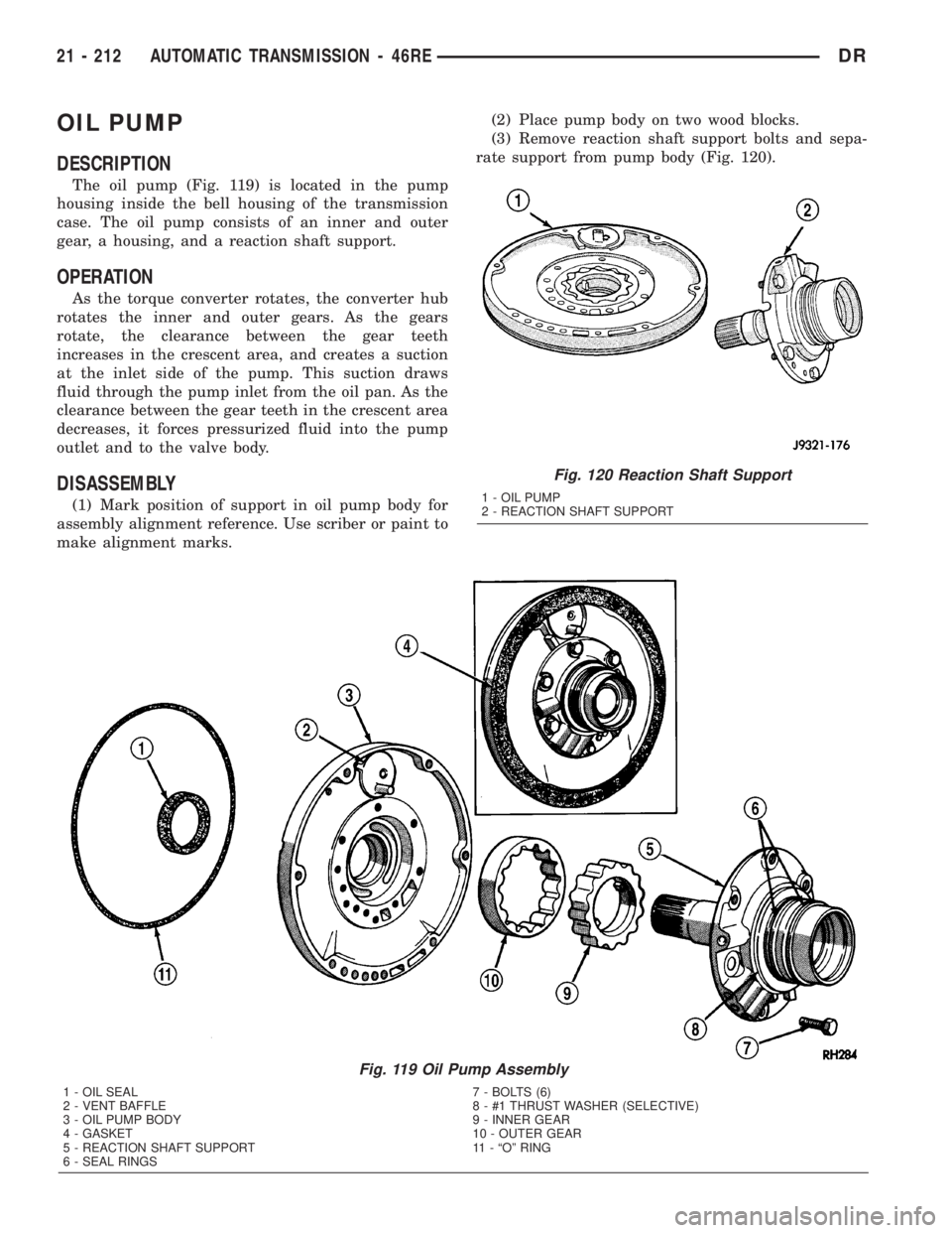
The oil pump (Fig. 119) is located in the pump
housing inside the bell housing of the transmission
case. The oil pump consists of an inner and outer
gear, a housing, and a reaction shaft support.
OPERATION
As the torque converter rotates, the converter hub
rotates the inner and outer gears. As the gears
rotate, the clearance between the gear teeth
increases in the crescent area, and creates a suction
at the inlet side of the pump. This suction draws
fluid through the pump inlet from the oil pan. As the
clearance between the gear teeth in the crescent area
decreases, it forces pressurized fluid into the pump
outlet and to the valve body.
DISASSEMBLY
(1) Mark position of support in oil pump body for
assembly alignment reference. Use scriber or paint to
make alignment marks.(2) Place pump body on two wood blocks.
(3) Remove reaction shaft support bolts and sepa-
rate support from pump body (Fig. 120).
Fig. 119 Oil Pump Assembly
1 - OIL SEAL 7 - BOLTS (6)
2 - VENT BAFFLE 8 - #1 THRUST WASHER (SELECTIVE)
3 - OIL PUMP BODY 9 - INNER GEAR
4 - GASKET 10 - OUTER GEAR
5 - REACTION SHAFT SUPPORT 11 - ªOº RING
6 - SEAL RINGS
Fig. 120 Reaction Shaft Support
1 - OIL PUMP
2 - REACTION SHAFT SUPPORT
21 - 212 AUTOMATIC TRANSMISSION - 46REDR
Page 2055 of 2895
REACTION SHAFT SUPPORT BUSHING
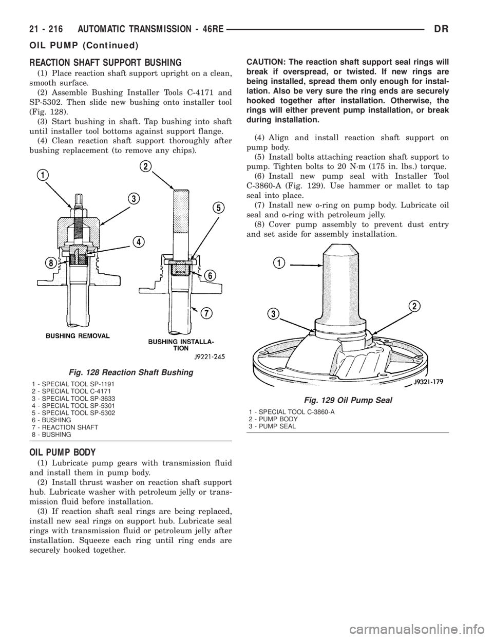
(1) Place reaction shaft support upright on a clean,
smooth surface.
(2) Assemble Bushing Installer Tools C-4171 and
SP-5302. Then slide new bushing onto installer tool
(Fig. 128).
(3) Start bushing in shaft. Tap bushing into shaft
until installer tool bottoms against support flange.
(4) Clean reaction shaft support thoroughly after
bushing replacement (to remove any chips).
OIL PUMP BODY
(1) Lubricate pump gears with transmission fluid
and install them in pump body.
(2) Install thrust washer on reaction shaft support
hub. Lubricate washer with petroleum jelly or trans-
mission fluid before installation.
(3) If reaction shaft seal rings are being replaced,
install new seal rings on support hub. Lubricate seal
rings with transmission fluid or petroleum jelly after
installation. Squeeze each ring until ring ends are
securely hooked together.CAUTION: The reaction shaft support seal rings will
break if overspread, or twisted. If new rings are
being installed, spread them only enough for instal-
lation. Also be very sure the ring ends are securely
hooked together after installation. Otherwise, the
rings will either prevent pump installation, or break
during installation.
(4) Align and install reaction shaft support on
pump body.
(5) Install bolts attaching reaction shaft support to
pump. Tighten bolts to 20 N´m (175 in. lbs.) torque.
(6) Install new pump seal with Installer Tool
C-3860-A (Fig. 129). Use hammer or mallet to tap
seal into place.
(7) Install new o-ring on pump body. Lubricate oil
seal and o-ring with petroleum jelly.
(8) Cover pump assembly to prevent dust entry
and set aside for assembly installation.
Fig. 128 Reaction Shaft Bushing
1 - SPECIAL TOOL SP-1191
2 - SPECIAL TOOL C-4171
3 - SPECIAL TOOL SP-3633
4 - SPECIAL TOOL SP-5301
5 - SPECIAL TOOL SP-5302
6 - BUSHING
7 - REACTION SHAFT
8 - BUSHING
Fig. 129 Oil Pump Seal
1 - SPECIAL TOOL C-3860-A
2 - PUMP BODY
3 - PUMP SEAL
21 - 216 AUTOMATIC TRANSMISSION - 46REDR
OIL PUMP (Continued)
Page 2057 of 2895
OVERDRIVE CLUTCH
DESCRIPTION
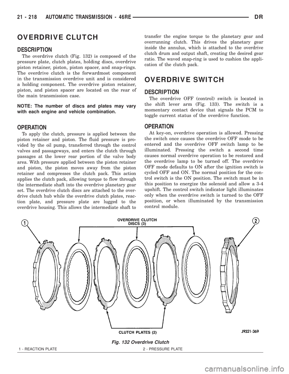
The overdrive clutch (Fig. 132) is composed of the
pressure plate, clutch plates, holding discs, overdrive
piston retainer, piston, piston spacer, and snap-rings.
The overdrive clutch is the forwardmost component
in the transmission overdrive unit and is considered
a holding component. The overdrive piston retainer,
piston, and piston spacer are located on the rear of
the main transmission case.
NOTE: The number of discs and plates may vary
with each engine and vehicle combination.
OPERATION
To apply the clutch, pressure is applied between the
piston retainer and piston. The fluid pressure is pro-
vided by the oil pump, transferred through the control
valves and passageways, and enters the clutch through
passages at the lower rear portion of the valve body
area. With pressure applied between the piston retainer
and piston, the piston moves away from the piston
retainer and compresses the clutch pack. This action
applies the clutch pack, allowing torque to flow through
the intermediate shaft into the overdrive planetary gear
set. The overdrive clutch discs are attached to the over-
drive clutch hub while the overdrive clutch plates, reac-
tion plate, and pressure plate are lugged to the
overdrive housing. This allows the intermediate shaft totransfer the engine torque to the planetary gear and
overrunning clutch. This drives the planetary gear
inside the annulus, which is attached to the overdrive
clutch drum and output shaft, creating the desired gear
ratio. The waved snap-ring is used to cushion the appli-
cation of the clutch pack.
OVERDRIVE SWITCH
DESCRIPTION
The overdrive OFF (control) switch is located in
the shift lever arm (Fig. 133). The switch is a
momentary contact device that signals the PCM to
toggle current status of the overdrive function.
OPERATION
At key-on, overdrive operation is allowed. Pressing
the switch once causes the overdrive OFF mode to be
entered and the overdrive OFF switch lamp to be
illuminated. Pressing the switch a second time
causes normal overdrive operation to be restored and
the overdrive lamp to be turned off. The overdrive
OFF mode defaults to ON after the ignition switch is
cycled OFF and ON. The normal position for the con-
trol switch is the ON position. The switch must be in
this position to energize the solenoid and allow a 3-4
upshift. The control switch indicator light illuminates
only when the overdrive switch is turned to the OFF
position, or when illuminated by the transmission
control module.
Fig. 132 Overdrive Clutch
1 - REACTION PLATE 2 - PRESSURE PLATE
21 - 218 AUTOMATIC TRANSMISSION - 46REDR
Page 2059 of 2895
OVERDRIVE UNIT
REMOVAL
(1) Shift transmission into PARK.
(2) Raise vehicle.
(3) Remove transfer case, if equipped.
(4) Mark propeller shaft universal joint(s) and axle
pinion yoke, or the companion flange and flange
yoke, for alignment reference at installation, if neces-
sary.
(5) Disconnect and remove the rear propeller shaft,
if necessary. (Refer to 3 - DIFFERENTIAL & DRIV-
ELINE/PROPELLER SHAFT/PROPELLER SHAFT -
REMOVAL)
(6) Remove transmission oil pan, remove gasket,
drain oil and reinstall pan.
(7) If overdrive unit had malfunctioned, or if fluid
is contaminated, remove entire transmission. If diag-
nosis indicated overdrive problems only, remove just
the overdrive unit.
(8) Support transmission with transmission jack.
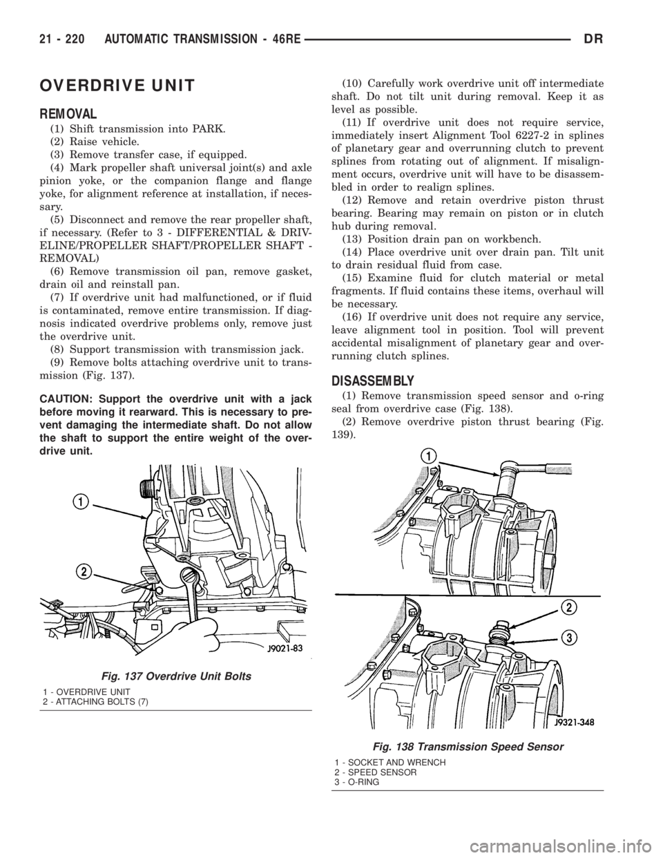
(9) Remove bolts attaching overdrive unit to trans-
mission (Fig. 137).
CAUTION: Support the overdrive unit with a jack
before moving it rearward. This is necessary to pre-
vent damaging the intermediate shaft. Do not allow
the shaft to support the entire weight of the over-
drive unit.(10) Carefully work overdrive unit off intermediate
shaft. Do not tilt unit during removal. Keep it as
level as possible.
(11) If overdrive unit does not require service,
immediately insert Alignment Tool 6227-2 in splines
of planetary gear and overrunning clutch to prevent
splines from rotating out of alignment. If misalign-
ment occurs, overdrive unit will have to be disassem-
bled in order to realign splines.
(12) Remove and retain overdrive piston thrust
bearing. Bearing may remain on piston or in clutch
hub during removal.
(13) Position drain pan on workbench.
(14) Place overdrive unit over drain pan. Tilt unit
to drain residual fluid from case.
(15) Examine fluid for clutch material or metal
fragments. If fluid contains these items, overhaul will
be necessary.
(16) If overdrive unit does not require any service,
leave alignment tool in position. Tool will prevent
accidental misalignment of planetary gear and over-
running clutch splines.
DISASSEMBLY
(1) Remove transmission speed sensor and o-ring
seal from overdrive case (Fig. 138).
(2) Remove overdrive piston thrust bearing (Fig.
139).
Fig. 137 Overdrive Unit Bolts
1 - OVERDRIVE UNIT
2 - ATTACHING BOLTS (7)
Fig. 138 Transmission Speed Sensor
1 - SOCKET AND WRENCH
2 - SPEED SENSOR
3 - O-RING
21 - 220 AUTOMATIC TRANSMISSION - 46REDR
Page 2066 of 2895
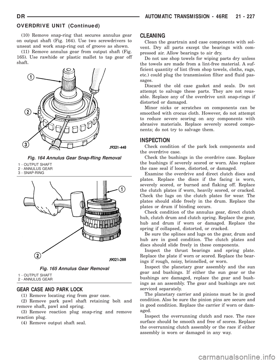
(10) Remove snap-ring that secures annulus gear
on output shaft (Fig. 164). Use two screwdrivers to
unseat and work snap-ring out of groove as shown.
(11) Remove annulus gear from output shaft (Fig.
165). Use rawhide or plastic mallet to tap gear off
shaft.
GEAR CASE AND PARK LOCK
(1) Remove locating ring from gear case.
(2) Remove park pawl shaft retaining bolt and
remove shaft, pawl and spring.
(3) Remove reaction plug snap-ring and remove
reaction plug.
(4) Remove output shaft seal.
CLEANING
Clean the geartrain and case components with sol-
vent. Dry all parts except the bearings with com-
pressed air. Allow bearings to air dry.
Do not use shop towels for wiping parts dry unless
the towels are made from a lint-free material. A suf-
ficient quantity of lint (from shop towels, cloths, rags,
etc.) could plug the transmission filter and fluid pas-
sages.
Discard the old case gasket and seals. Do not
attempt to salvage these parts. They are not reus-
able. Replace any of the overdrive unit snap-rings if
distorted or damaged.
Minor nicks or scratches on components can be
smoothed with crocus cloth. However, do not attempt
to reduce severe scoring on any components with
abrasive materials. Replace severely scored compo-
nents; do not try to salvage them.
INSPECTION
Check condition of the park lock components and
the overdrive case.
Check the bushings in the overdrive case. Replace
the bushings if severely scored or worn. Also replace
the case seal if loose, distorted, or damaged.
Examine the overdrive and direct clutch discs and
plates. Replace the discs if the facing is worn,
severely scored, or burned and flaking off. Replace
the clutch plates if worn, heavily scored, or cracked.
Check the lugs on the clutch plates for wear. The
plates should slide freely in the drum. Replace the
plates or drum if binding occurs.
Check condition of the annulus gear, direct clutch
hub, clutch drum and clutch spring. Replace the gear,
hub and drum if worn or damaged. Replace the
spring if collapsed, distorted, or cracked.
Be sure the splines and lugs on the gear, drum and
hub are in good condition. The clutch plates and
discs should slide freely in these components.
Inspect the thrust bearings and spring plate.
Replace the plate if worn or scored. Replace the bear-
ings if rough, noisy, brinnelled, or worn.
Inspect the planetary gear assembly and the sun
gear and bushings. If either the sun gear or the
bushings are damaged, replace the gear and bush-
ings as an assembly. The gear and bushings are not
serviced separately.
The planetary carrier and pinions must be in good
condition. Also be sure the pinion pins are secure and
in good condition. Replace the carrier if worn or dam-
aged.
Inspect the overrunning clutch and race. The race
surface should be smooth and free of scores. Replace
the overrunning clutch assembly or the race if either
assembly is worn or damaged in any way.
Fig. 164 Annulus Gear Snap-Ring Removal
1 - OUTPUT SHAFT
2 - ANNULUS GEAR
3 - SNAP-RING
Fig. 165 Annulus Gear Removal
1 - OUTPUT SHAFT
2 - ANNULUS GEAR
DRAUTOMATIC TRANSMISSION - 46RE 21 - 227
OVERDRIVE UNIT (Continued)