2003 DODGE RAM automatic transmission fluid
[x] Cancel search: automatic transmission fluidPage 2105 of 2895
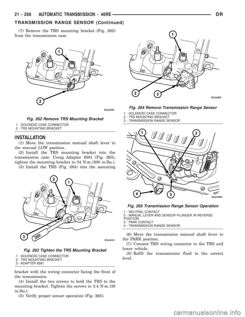
(7) Remove the TRS mounting bracket (Fig. 262)
from the transmission case.
INSTALLATION
(1) Move the transmission manual shaft lever to
the manual LOW position.
(2) Install the TRS mounting bracket into the
transmission case. Using Adapter 8581 (Fig. 263),
tighten the mounting bracket to 34 N´m (300 in.lbs.).
(3) Install the TRS (Fig. 264) into the mounting
bracket with the wiring connector facing the front of
the transmission.
(4) Install the two screws to hold the TRS to the
mounting bracket. Tighten the screws to 3.4 N´m (30
in.lbs.).
(5) Verify proper sensor operation (Fig. 265).(6) Move the transmission manual shaft lever to
the PARK position.
(7) Connect TRS wiring connector to the TRS and
lower vehicle.
(8) Refill the transmission fluid to the correct
level.
Fig. 262 Remove TRS Mounting Bracket
1 - SOLENOID CASE CONNECTOR
2 - TRS MOUNTING BRACKET
Fig. 263 Tighten the TRS Mounting Bracket
1 - SOLENOID CASE CONNECTOR
2 - TRS MOUNTING BRACKET
3 - ADAPTER 8581
Fig. 264 Remove Transmission Range Sensor
1 - SOLENOID CASE CONNECTOR
2 - TRS MOUNTING BRACKET
3 - TRANSMISSION RANGE SENSOR
Fig. 265 Transmission Range Sensor Operation
1 - NEUTRAL CONTACT
2 - MANUAL LEVER AND SENSOR PLUNGER IN REVERSE
POSITION
3 - PARK CONTACT
4 - TRANSMISSION RANGE SENSOR
21 - 266 AUTOMATIC TRANSMISSION - 46REDR
TRANSMISSION RANGE SENSOR (Continued)
Page 2106 of 2895
TRANSMISSION
TEMPERATURE SENSOR
DESCRIPTION
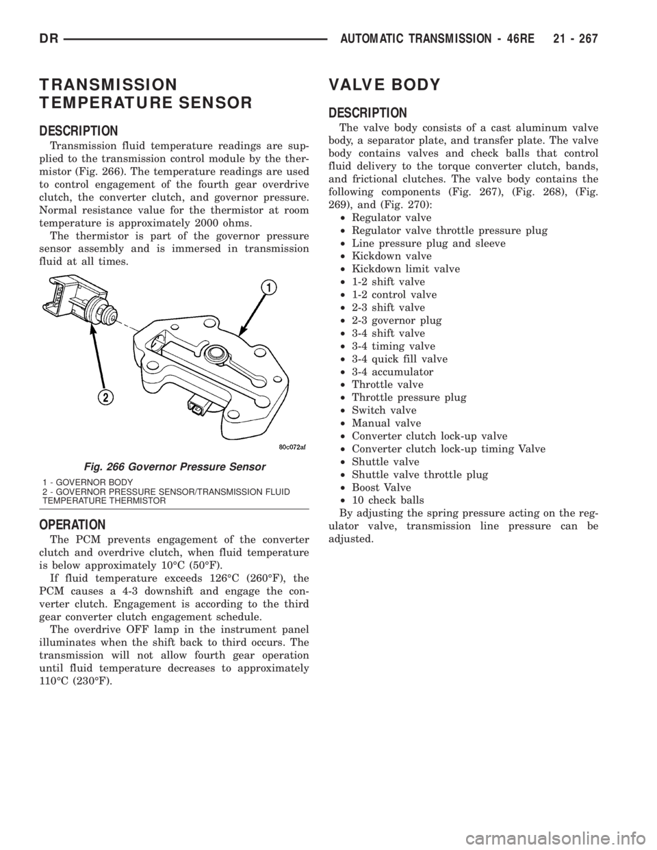
Transmission fluid temperature readings are sup-
plied to the transmission control module by the ther-
mistor (Fig. 266). The temperature readings are used
to control engagement of the fourth gear overdrive
clutch, the converter clutch, and governor pressure.
Normal resistance value for the thermistor at room
temperature is approximately 2000 ohms.
The thermistor is part of the governor pressure
sensor assembly and is immersed in transmission
fluid at all times.
OPERATION
The PCM prevents engagement of the converter
clutch and overdrive clutch, when fluid temperature
is below approximately 10ÉC (50ÉF).
If fluid temperature exceeds 126ÉC (260ÉF), the
PCM causes a 4-3 downshift and engage the con-
verter clutch. Engagement is according to the third
gear converter clutch engagement schedule.
The overdrive OFF lamp in the instrument panel
illuminates when the shift back to third occurs. The
transmission will not allow fourth gear operation
until fluid temperature decreases to approximately
110ÉC (230ÉF).
VALVE BODY
DESCRIPTION
The valve body consists of a cast aluminum valve
body, a separator plate, and transfer plate. The valve
body contains valves and check balls that control
fluid delivery to the torque converter clutch, bands,
and frictional clutches. The valve body contains the
following components (Fig. 267), (Fig. 268), (Fig.
269), and (Fig. 270):
²Regulator valve
²Regulator valve throttle pressure plug
²Line pressure plug and sleeve
²Kickdown valve
²Kickdown limit valve
²1-2 shift valve
²1-2 control valve
²2-3 shift valve
²2-3 governor plug
²3-4 shift valve
²3-4 timing valve
²3-4 quick fill valve
²3-4 accumulator
²Throttle valve
²Throttle pressure plug
²Switch valve
²Manual valve
²Converter clutch lock-up valve
²Converter clutch lock-up timing Valve
²Shuttle valve
²Shuttle valve throttle plug
²Boost Valve
²10 check balls
By adjusting the spring pressure acting on the reg-
ulator valve, transmission line pressure can be
adjusted.
Fig. 266 Governor Pressure Sensor
1 - GOVERNOR BODY
2 - GOVERNOR PRESSURE SENSOR/TRANSMISSION FLUID
TEMPERATURE THERMISTOR
DRAUTOMATIC TRANSMISSION - 46RE 21 - 267
Page 2111 of 2895
OPERATION
NOTE: Refer to the Hydraulic Schematics for a visual
aid in determining valve location, operation and design.
CHECK BALLS
CHECK BALL
NUMBERDESCRIPTION
1 Allows either the manual valve to put line pressure on the 1-2 governor plug or the KD Valve to
put WOT line pressure on the 1-2 governor plug.
2 Allows either the manual valve to put line pressure on the 2-3 governor plug or the KD Valve to
put WOT line pressure on the 2-3 governor plug.
3 Allows either the Reverse circuit or the 3rd gear circuit to pressurize the front clutch.
4 Allows either the Manual Low circuit from the Manual Valve or the Reverse from the Manual
Valve circuit to pressurize the rear servo.
5 Directs line pressure to the spring end of the 2-3 shift valve in either Manual Low or Manual
2nd, forcing the downshift to 2nd gear regardless of governor pressure.
6 Provides a by-pass around the front servo orifice so that the servo can release quickly.
7 Provides a by-pass around the rear clutch orifice so that the clutch can release quickly.
8 Directs reverse line pressure through an orifice to the throttle valve eliminating the extra
leakage and insuring that Reverse line pressure pressure will be sufficient.
9 Provides a by-pass around the rear servo orifice so that the servo can release quickly.
10 Allows the lockup clutch to used at WOT in 3rd gear by putting line pressure from the 3-4
Timing Valve on the interlock area of the 2-3 shift valve, thereby preventing a 3rd gear Lock-up
to 2nd gear kickdown.
REGULATOR VALVE
The pressure regulator valve is needed to control
the hydraulic pressure within the system and reduce
the amount of heat produced in the fluid. The pres-
sure regulator valve is located in the valve body near
the manual valve. The pressure regulator valve train
controls the maximum pressure in the lines by
metering the dumping of fluid back into the sump.
Regulated pressure is referred to as ªline pressure.º
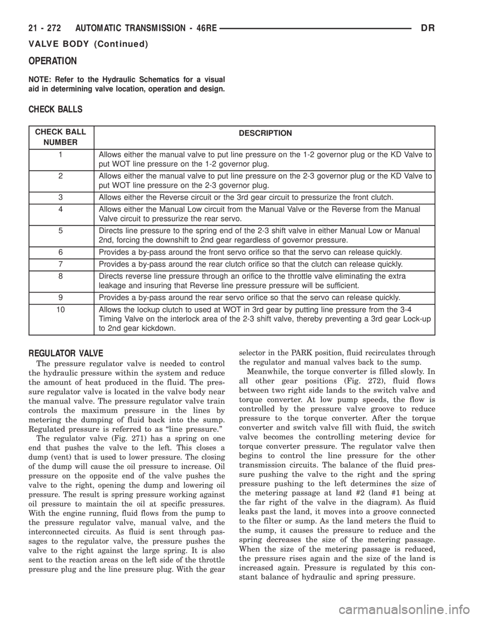
The regulator valve (Fig. 271) has a spring on one
end that pushes the valve to the left. This closes a
dump (vent) that is used to lower pressure. The closing
of the dump will cause the oil pressure to increase. Oil
pressure on the opposite end of the valve pushes the
valve to the right, opening the dump and lowering oil
pressure. The result is spring pressure working against
oil pressure to maintain the oil at specific pressures.
With the engine running, fluid flows from the pump to
the pressure regulator valve, manual valve, and the
interconnected circuits. As fluid is sent through pas-
sages to the regulator valve, the pressure pushes the
valve to the right against the large spring. It is also
sent to the reaction areas on the left side of the throttle
pressure plug and the line pressure plug. With the gearselector in the PARK position, fluid recirculates through
the regulator and manual valves back to the sump.
Meanwhile, the torque converter is filled slowly. In
all other gear positions (Fig. 272), fluid flows
between two right side lands to the switch valve and
torque converter. At low pump speeds, the flow is
controlled by the pressure valve groove to reduce
pressure to the torque converter. After the torque
converter and switch valve fill with fluid, the switch
valve becomes the controlling metering device for
torque converter pressure. The regulator valve then
begins to control the line pressure for the other
transmission circuits. The balance of the fluid pres-
sure pushing the valve to the right and the spring
pressure pushing to the left determines the size of
the metering passage at land #2 (land #1 being at
the far right of the valve in the diagram). As fluid
leaks past the land, it moves into a groove connected
to the filter or sump. As the land meters the fluid to
the sump, it causes the pressure to reduce and the
spring decreases the size of the metering passage.
When the size of the metering passage is reduced,
the pressure rises again and the size of the land is
increased again. Pressure is regulated by this con-
stant balance of hydraulic and spring pressure.
21 - 272 AUTOMATIC TRANSMISSION - 46REDR
VALVE BODY (Continued)
Page 2113 of 2895
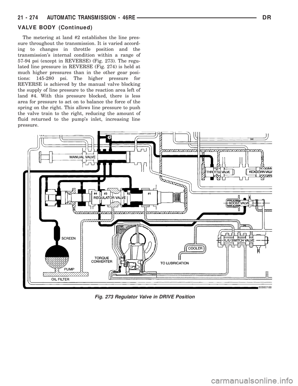
The metering at land #2 establishes the line pres-
sure throughout the transmission. It is varied accord-
ing to changes in throttle position and the
transmission's internal condition within a range of
57-94 psi (except in REVERSE) (Fig. 273). The regu-
lated line pressure in REVERSE (Fig. 274) is held at
much higher pressures than in the other gear posi-
tions: 145-280 psi. The higher pressure for
REVERSE is achieved by the manual valve blocking
the supply of line pressure to the reaction area left of
land #4. With this pressure blocked, there is less
area for pressure to act on to balance the force of the
spring on the right. This allows line pressure to push
the valve train to the right, reducing the amount of
fluid returned to the pump's inlet, increasing line
pressure.
Fig. 273 Regulator Valve in DRIVE Position
21 - 274 AUTOMATIC TRANSMISSION - 46REDR
VALVE BODY (Continued)
Page 2115 of 2895
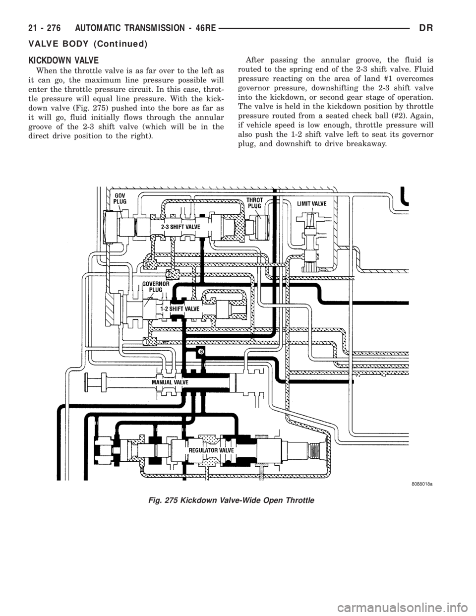
KICKDOWN VALVE
When the throttle valve is as far over to the left as
it can go, the maximum line pressure possible will
enter the throttle pressure circuit. In this case, throt-
tle pressure will equal line pressure. With the kick-
down valve (Fig. 275) pushed into the bore as far as
it will go, fluid initially flows through the annular
groove of the 2-3 shift valve (which will be in the
direct drive position to the right).After passing the annular groove, the fluid is
routed to the spring end of the 2-3 shift valve. Fluid
pressure reacting on the area of land #1 overcomes
governor pressure, downshifting the 2-3 shift valve
into the kickdown, or second gear stage of operation.
The valve is held in the kickdown position by throttle
pressure routed from a seated check ball (#2). Again,
if vehicle speed is low enough, throttle pressure will
also push the 1-2 shift valve left to seat its governor
plug, and downshift to drive breakaway.
Fig. 275 Kickdown Valve-Wide Open Throttle
21 - 276 AUTOMATIC TRANSMISSION - 46REDR
VALVE BODY (Continued)
Page 2122 of 2895
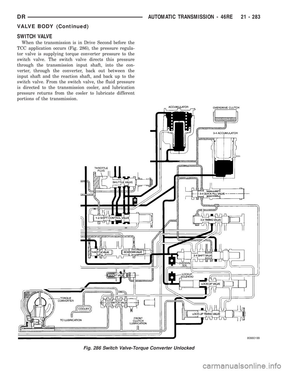
SWITCH VALVE
When the transmission is in Drive Second before the
TCC application occurs (Fig. 286), the pressure regula-
tor valve is supplying torque converter pressure to the
switch valve. The switch valve directs this pressure
through the transmission input shaft, into the con-
verter, through the converter, back out between the
input shaft and the reaction shaft, and back up to the
switch valve. From the switch valve, the fluid pressure
is directed to the transmission cooler, and lubrication
pressure returns from the cooler to lubricate different
portions of the transmission.
Fig. 286 Switch Valve-Torque Converter Unlocked
DRAUTOMATIC TRANSMISSION - 46RE 21 - 283
VALVE BODY (Continued)
Page 2124 of 2895
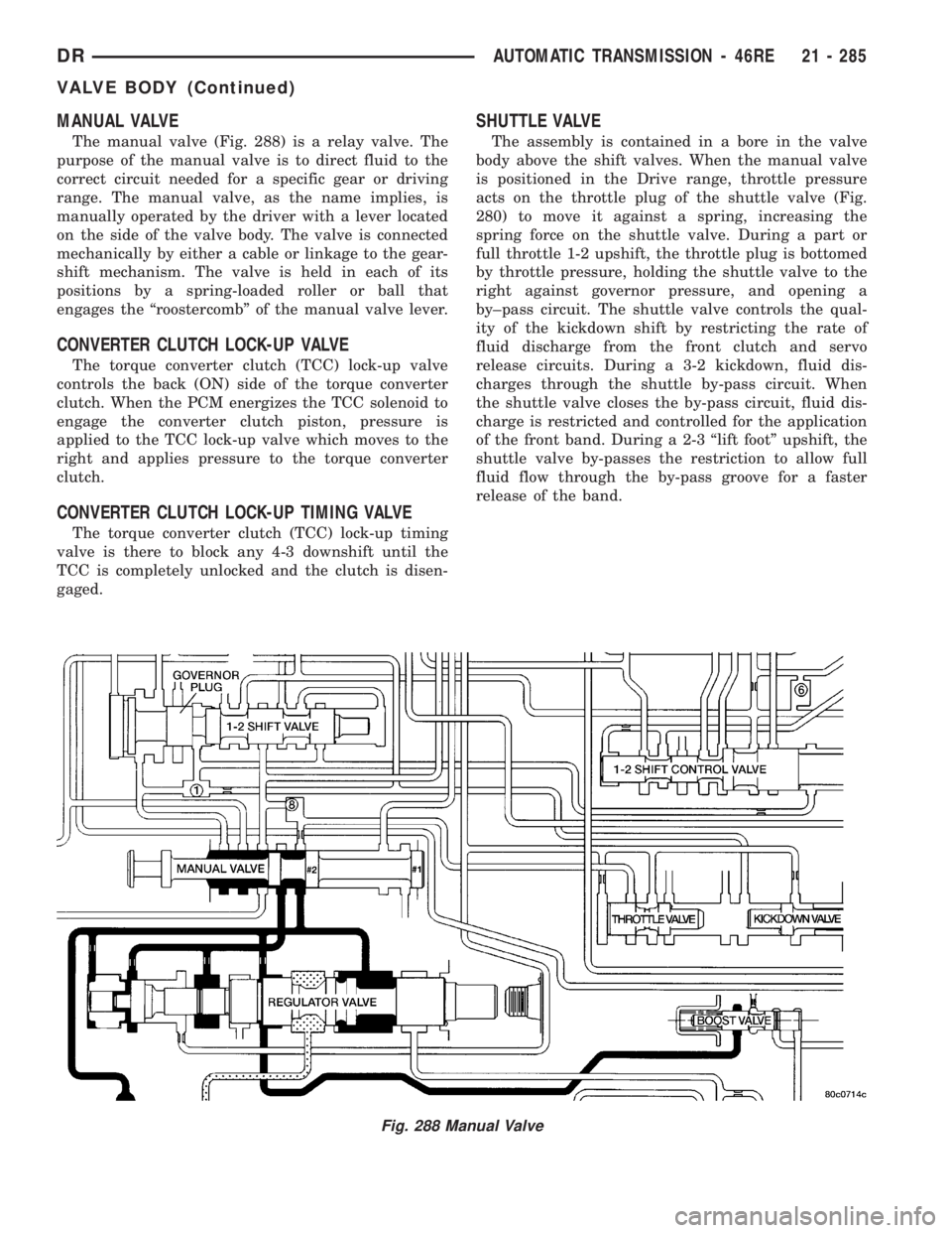
MANUAL VALVE
The manual valve (Fig. 288) is a relay valve. The
purpose of the manual valve is to direct fluid to the
correct circuit needed for a specific gear or driving
range. The manual valve, as the name implies, is
manually operated by the driver with a lever located
on the side of the valve body. The valve is connected
mechanically by either a cable or linkage to the gear-
shift mechanism. The valve is held in each of its
positions by a spring-loaded roller or ball that
engages the ªroostercombº of the manual valve lever.
CONVERTER CLUTCH LOCK-UP VALVE
The torque converter clutch (TCC) lock-up valve
controls the back (ON) side of the torque converter
clutch. When the PCM energizes the TCC solenoid to
engage the converter clutch piston, pressure is
applied to the TCC lock-up valve which moves to the
right and applies pressure to the torque converter
clutch.
CONVERTER CLUTCH LOCK-UP TIMING VALVE
The torque converter clutch (TCC) lock-up timing
valve is there to block any 4-3 downshift until the
TCC is completely unlocked and the clutch is disen-
gaged.
SHUTTLE VALVE
The assembly is contained in a bore in the valve
body above the shift valves. When the manual valve
is positioned in the Drive range, throttle pressure
acts on the throttle plug of the shuttle valve (Fig.
280) to move it against a spring, increasing the
spring force on the shuttle valve. During a part or
full throttle 1-2 upshift, the throttle plug is bottomed
by throttle pressure, holding the shuttle valve to the
right against governor pressure, and opening a
by±pass circuit. The shuttle valve controls the qual-
ity of the kickdown shift by restricting the rate of
fluid discharge from the front clutch and servo
release circuits. During a 3-2 kickdown, fluid dis-
charges through the shuttle by-pass circuit. When
the shuttle valve closes the by-pass circuit, fluid dis-
charge is restricted and controlled for the application
of the front band. During a 2-3 ªlift footº upshift, the
shuttle valve by-passes the restriction to allow full
fluid flow through the by-pass groove for a faster
release of the band.
Fig. 288 Manual Valve
DRAUTOMATIC TRANSMISSION - 46RE 21 - 285
VALVE BODY (Continued)
Page 2125 of 2895
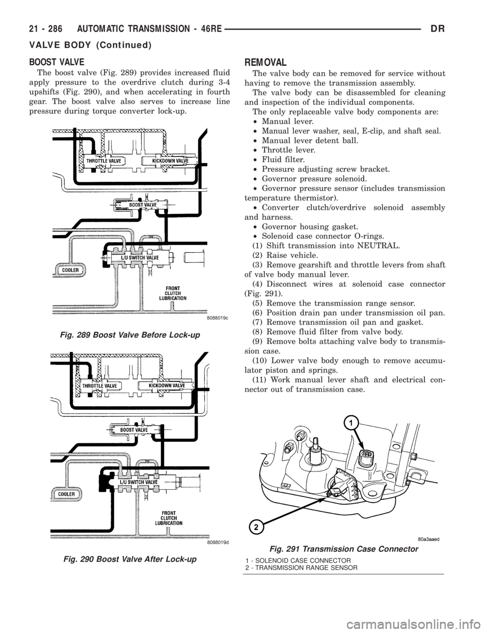
BOOST VALVE
The boost valve (Fig. 289) provides increased fluid
apply pressure to the overdrive clutch during 3-4
upshifts (Fig. 290), and when accelerating in fourth
gear. The boost valve also serves to increase line
pressure during torque converter lock-up.
REMOVAL
The valve body can be removed for service without
having to remove the transmission assembly.
The valve body can be disassembled for cleaning
and inspection of the individual components.
The only replaceable valve body components are:
²Manual lever.
²
Manual lever washer, seal, E-clip, and shaft seal.
²Manual lever detent ball.
²Throttle lever.
²Fluid filter.
²Pressure adjusting screw bracket.
²Governor pressure solenoid.
²Governor pressure sensor (includes transmission
temperature thermistor).
²Converter clutch/overdrive solenoid assembly
and harness.
²Governor housing gasket.
²Solenoid case connector O-rings.
(1) Shift transmission into NEUTRAL.
(2) Raise vehicle.
(3) Remove gearshift and throttle levers from shaft
of valve body manual lever.
(4) Disconnect wires at solenoid case connector
(Fig. 291).
(5) Remove the transmission range sensor.
(6) Position drain pan under transmission oil pan.
(7) Remove transmission oil pan and gasket.
(8) Remove fluid filter from valve body.
(9) Remove bolts attaching valve body to transmis-
sion case.
(10) Lower valve body enough to remove accumu-
lator piston and springs.
(11) Work manual lever shaft and electrical con-
nector out of transmission case.
Fig. 291 Transmission Case Connector
1 - SOLENOID CASE CONNECTOR
2 - TRANSMISSION RANGE SENSOR
Fig. 289 Boost Valve Before Lock-up
Fig. 290 Boost Valve After Lock-up
21 - 286 AUTOMATIC TRANSMISSION - 46REDR
VALVE BODY (Continued)