2003 DODGE RAM automatic transmission fluid
[x] Cancel search: automatic transmission fluidPage 2185 of 2895
shafts, or valves, use extreme care to avoid rounding
off sharp edges. Sharp edges are vital as they pre-
vent foreign matter from getting between the valve
and valve bore.
Do not reuse oil seals, gaskets, seal rings, or
O-rings during overhaul. Replace these parts as a
matter of course. Also do not reuse snap rings or
E-clips that are bent or distorted. Replace these parts
as well.
ASSEMBLY
CAUTION: If the condition of the transmission
before the overhaul procedure caused excessive
metallic or fiber contamination in the fluid, replace
the torque converter. Fluid contamination and trans-
mission failure can result if not done.
Do not allow dirt, grease, or foreign material to
enter the case or transmission components during
assembly. Keep the transmission case and compo-
nents clean. Also make sure the tools and workbench
area used for reassembly operations are equally
clean.
Shop towels used for wiping off tools and your
hands must be made fromlint freematerials. Lint
will stick to transmission parts and could interfere
with valve operation or even restrict fluid passages.
Lubricate transmission clutch and gear compo-
nents with MopartATF +4 during reassembly. Soak
clutch discs in transmission fluid before installation.
Petroleum jelly can be used to lubricate and hold
thrust washers and plates in position during assem-
bly.
Do not use chassis grease, bearing grease,
white grease, or similar lubricants on any part.
These types of lubricants can eventually block or
restrict fluid passages and valve operation. Use
petroleum jelly only.
Do not force parts into place. The transmission
components and sub-assemblies are easily installed
by hand when properly aligned. If a part seems dif-
ficult to install, it is either misaligned or incorrectly
assembled. Verify that thrust washers, thrust plates
and seal rings are correctly positioned.
The planetary geartrain, front/rear clutch assem-
blies and oil pump are all much easier to install
when the transmission case is upright. Either tilt the
case upward with wood blocks, or cut a hole in the
bench large enough for the intermediate shaft and
rear support. Then lower the shaft and support into
the hole and support the rear of the case directly on
the bench.
FRONT/REAR SERVO
(1) Lubricate rear servo piston seal with ATF +4.
Lubricate servo bore in case with ATF +4.
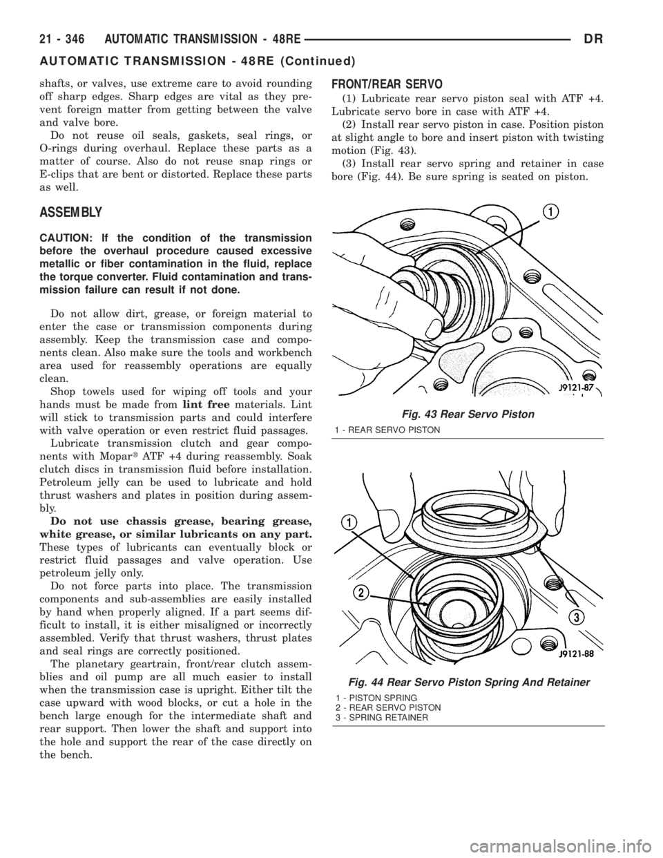
(2) Install rear servo piston in case. Position piston
at slight angle to bore and insert piston with twisting
motion (Fig. 43).
(3) Install rear servo spring and retainer in case
bore (Fig. 44). Be sure spring is seated on piston.
Fig. 43 Rear Servo Piston
1 - REAR SERVO PISTON
Fig. 44 Rear Servo Piston Spring And Retainer
1 - PISTON SPRING
2 - REAR SERVO PISTON
3 - SPRING RETAINER
21 - 346 AUTOMATIC TRANSMISSION - 48REDR
AUTOMATIC TRANSMISSION - 48RE (Continued)
Page 2186 of 2895
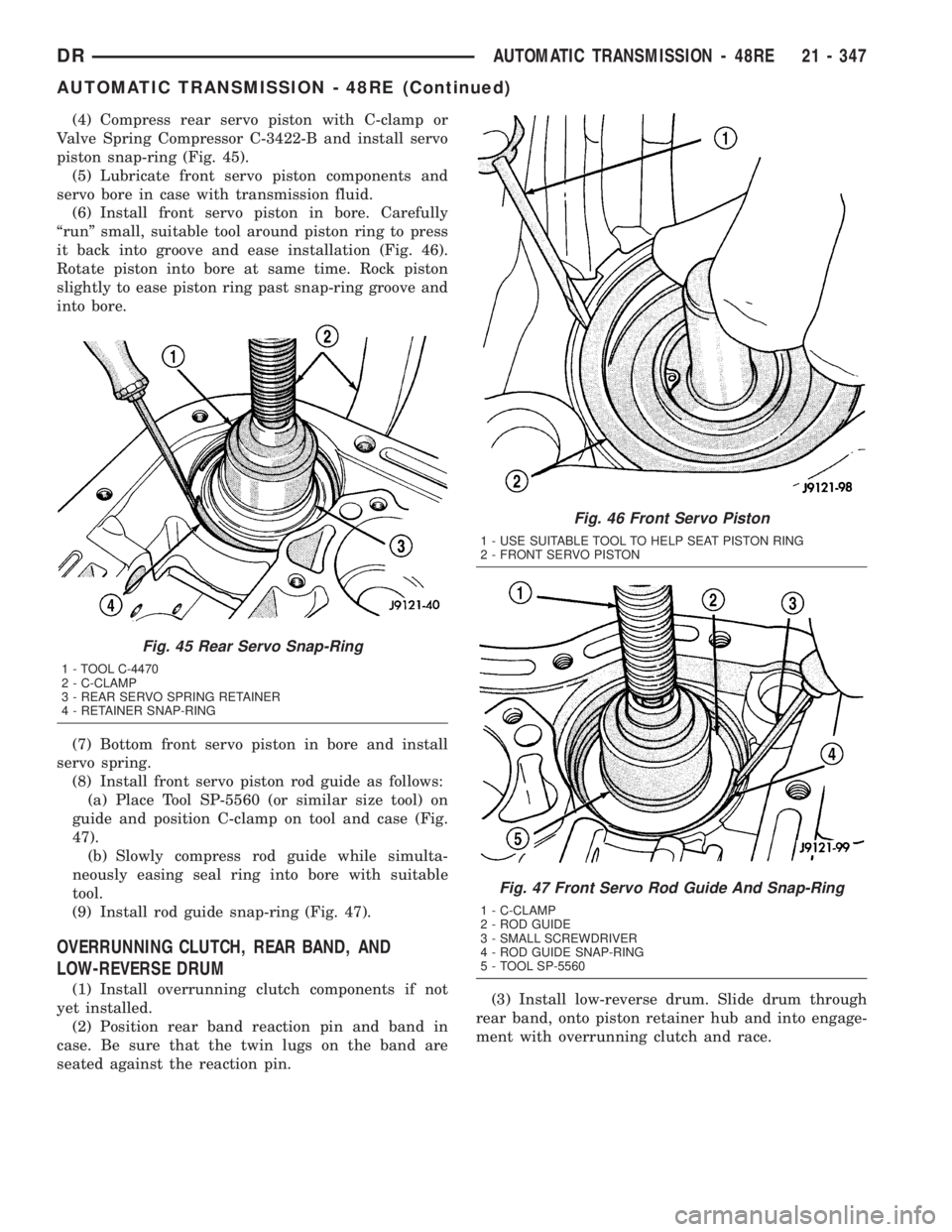
(4) Compress rear servo piston with C-clamp or
Valve Spring Compressor C-3422-B and install servo
piston snap-ring (Fig. 45).
(5) Lubricate front servo piston components and
servo bore in case with transmission fluid.
(6) Install front servo piston in bore. Carefully
ªrunº small, suitable tool around piston ring to press
it back into groove and ease installation (Fig. 46).
Rotate piston into bore at same time. Rock piston
slightly to ease piston ring past snap-ring groove and
into bore.
(7) Bottom front servo piston in bore and install
servo spring.
(8) Install front servo piston rod guide as follows:
(a) Place Tool SP-5560 (or similar size tool) on
guide and position C-clamp on tool and case (Fig.
47).
(b) Slowly compress rod guide while simulta-
neously easing seal ring into bore with suitable
tool.
(9) Install rod guide snap-ring (Fig. 47).
OVERRUNNING CLUTCH, REAR BAND, AND
LOW-REVERSE DRUM
(1) Install overrunning clutch components if not
yet installed.
(2) Position rear band reaction pin and band in
case. Be sure that the twin lugs on the band are
seated against the reaction pin.(3) Install low-reverse drum. Slide drum through
rear band, onto piston retainer hub and into engage-
ment with overrunning clutch and race.
Fig. 45 Rear Servo Snap-Ring
1 - TOOL C-4470
2 - C-CLAMP
3 - REAR SERVO SPRING RETAINER
4 - RETAINER SNAP-RING
Fig. 46 Front Servo Piston
1 - USE SUITABLE TOOL TO HELP SEAT PISTON RING
2 - FRONT SERVO PISTON
Fig. 47 Front Servo Rod Guide And Snap-Ring
1 - C-CLAMP
2 - ROD GUIDE
3 - SMALL SCREWDRIVER
4 - ROD GUIDE SNAP-RING
5 - TOOL SP-5560
DRAUTOMATIC TRANSMISSION - 48RE 21 - 347
AUTOMATIC TRANSMISSION - 48RE (Continued)
Page 2189 of 2895
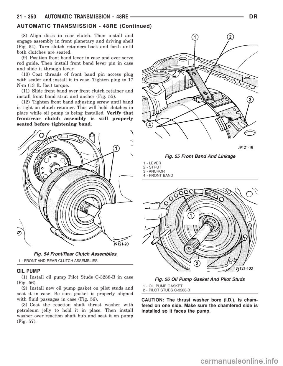
(8) Align discs in rear clutch. Then install and
engage assembly in front planetary and driving shell
(Fig. 54). Turn clutch retainers back and forth until
both clutches are seated.
(9) Position front band lever in case and over servo
rod guide. Then install front band lever pin in case
and slide it through lever.
(10) Coat threads of front band pin access plug
with sealer and install it in case. Tighten plug to 17
N´m (13 ft. lbs.) torque.
(11) Slide front band over front clutch retainer and
install front band strut and anchor (Fig. 55).
(12) Tighten front band adjusting screw until band
is tight on clutch retainer. This will hold clutches in
place while oil pump is being installed.Verify that
front/rear clutch assembly is still properly
seated before tightening band.
OIL PUMP
(1) Install oil pump Pilot Studs C-3288-B in case
(Fig. 56).
(2) Install new oil pump gasket on pilot studs and
seat it in case. Be sure gasket is properly aligned
with fluid passages in case (Fig. 56).
(3) Coat the reaction shaft thrust washer with
petroleum jelly to hold it in place. Then install
washer over reaction shaft hub and seat it on pump
(Fig. 57).CAUTION: The thrust washer bore (I.D.), is cham-
fered on one side. Make sure the chamfered side is
installed so it faces the pump.
Fig. 55 Front Band And Linkage
1 - LEVER
2 - STRUT
3 - ANCHOR
4 - FRONT BAND
Fig. 56 Oil Pump Gasket And Pilot Studs
1 - OIL PUMP GASKET
2 - PILOT STUDS C-3288-B
Fig. 54 Front/Rear Clutch Assemblies
1 - FRONT AND REAR CLUTCH ASSEMBLIES
21 - 350 AUTOMATIC TRANSMISSION - 48REDR
AUTOMATIC TRANSMISSION - 48RE (Continued)
Page 2191 of 2895
INPUT SHAFT END PLAY CHECK
NOTE: Overdrive unit must be installed in order to
correctly measure the input shaft end-play.
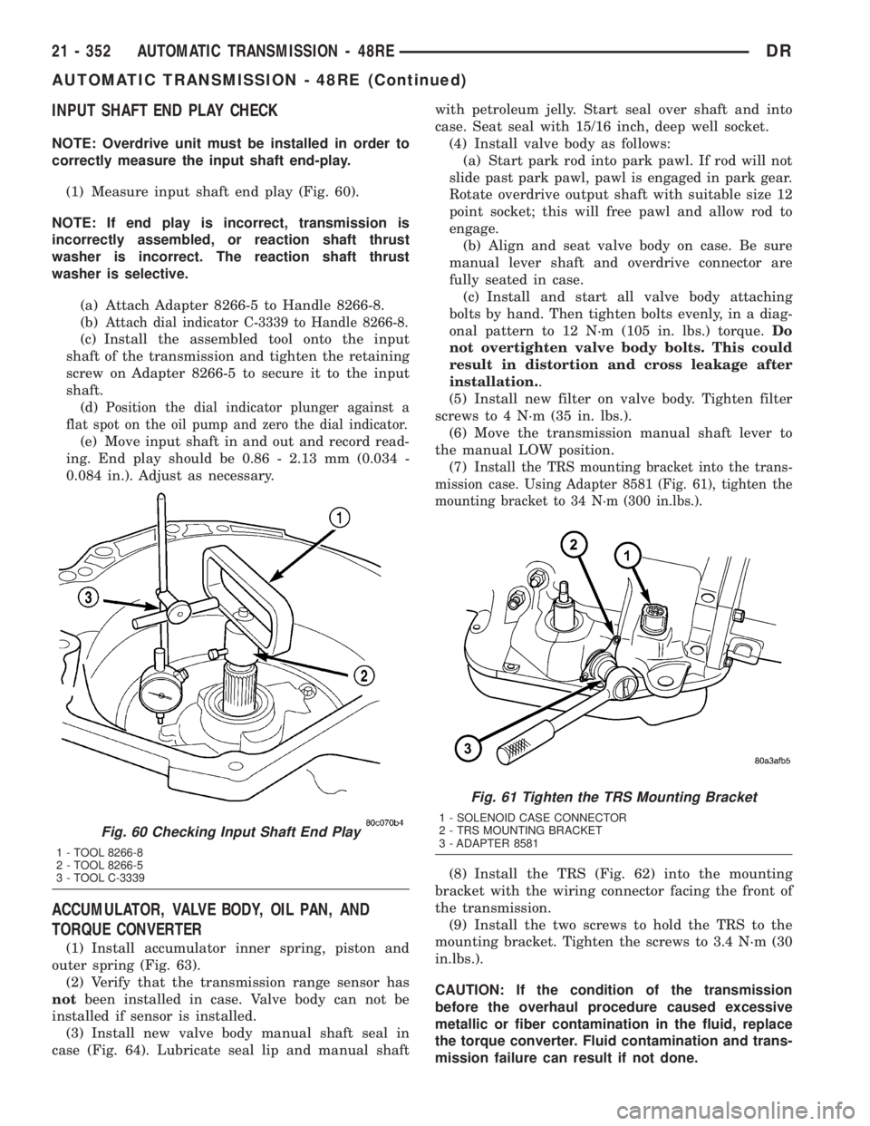
(1) Measure input shaft end play (Fig. 60).
NOTE: If end play is incorrect, transmission is
incorrectly assembled, or reaction shaft thrust
washer is incorrect. The reaction shaft thrust
washer is selective.
(a) Attach Adapter 8266-5 to Handle 8266-8.
(b)
Attach dial indicator C-3339 to Handle 8266-8.
(c) Install the assembled tool onto the input
shaft of the transmission and tighten the retaining
screw on Adapter 8266-5 to secure it to the input
shaft.
(d)
Position the dial indicator plunger against a
flat spot on the oil pump and zero the dial indicator.
(e) Move input shaft in and out and record read-
ing. End play should be 0.86 - 2.13 mm (0.034 -
0.084 in.). Adjust as necessary.
ACCUMULATOR, VALVE BODY, OIL PAN, AND
TORQUE CONVERTER
(1) Install accumulator inner spring, piston and
outer spring (Fig. 63).
(2) Verify that the transmission range sensor has
notbeen installed in case. Valve body can not be
installed if sensor is installed.
(3) Install new valve body manual shaft seal in
case (Fig. 64). Lubricate seal lip and manual shaftwith petroleum jelly. Start seal over shaft and into
case. Seat seal with 15/16 inch, deep well socket.
(4) Install valve body as follows:
(a) Start park rod into park pawl. If rod will not
slide past park pawl, pawl is engaged in park gear.
Rotate overdrive output shaft with suitable size 12
point socket; this will free pawl and allow rod to
engage.
(b) Align and seat valve body on case. Be sure
manual lever shaft and overdrive connector are
fully seated in case.
(c) Install and start all valve body attaching
bolts by hand. Then tighten bolts evenly, in a diag-
onal pattern to 12 N´m (105 in. lbs.) torque.Do
not overtighten valve body bolts. This could
result in distortion and cross leakage after
installation..
(5) Install new filter on valve body. Tighten filter
screws to 4 N´m (35 in. lbs.).
(6) Move the transmission manual shaft lever to
the manual LOW position.
(7)
Install the TRS mounting bracket into the trans-
mission case. Using Adapter 8581 (Fig. 61), tighten the
mounting bracket to 34 N´m (300 in.lbs.).
(8) Install the TRS (Fig. 62) into the mounting
bracket with the wiring connector facing the front of
the transmission.
(9) Install the two screws to hold the TRS to the
mounting bracket. Tighten the screws to 3.4 N´m (30
in.lbs.).
CAUTION: If the condition of the transmission
before the overhaul procedure caused excessive
metallic or fiber contamination in the fluid, replace
the torque converter. Fluid contamination and trans-
mission failure can result if not done.
Fig. 60 Checking Input Shaft End Play
1 - TOOL 8266-8
2 - TOOL 8266-5
3 - TOOL C-3339
Fig. 61 Tighten the TRS Mounting Bracket
1 - SOLENOID CASE CONNECTOR
2 - TRS MOUNTING BRACKET
3 - ADAPTER 8581
21 - 352 AUTOMATIC TRANSMISSION - 48REDR
AUTOMATIC TRANSMISSION - 48RE (Continued)
Page 2192 of 2895
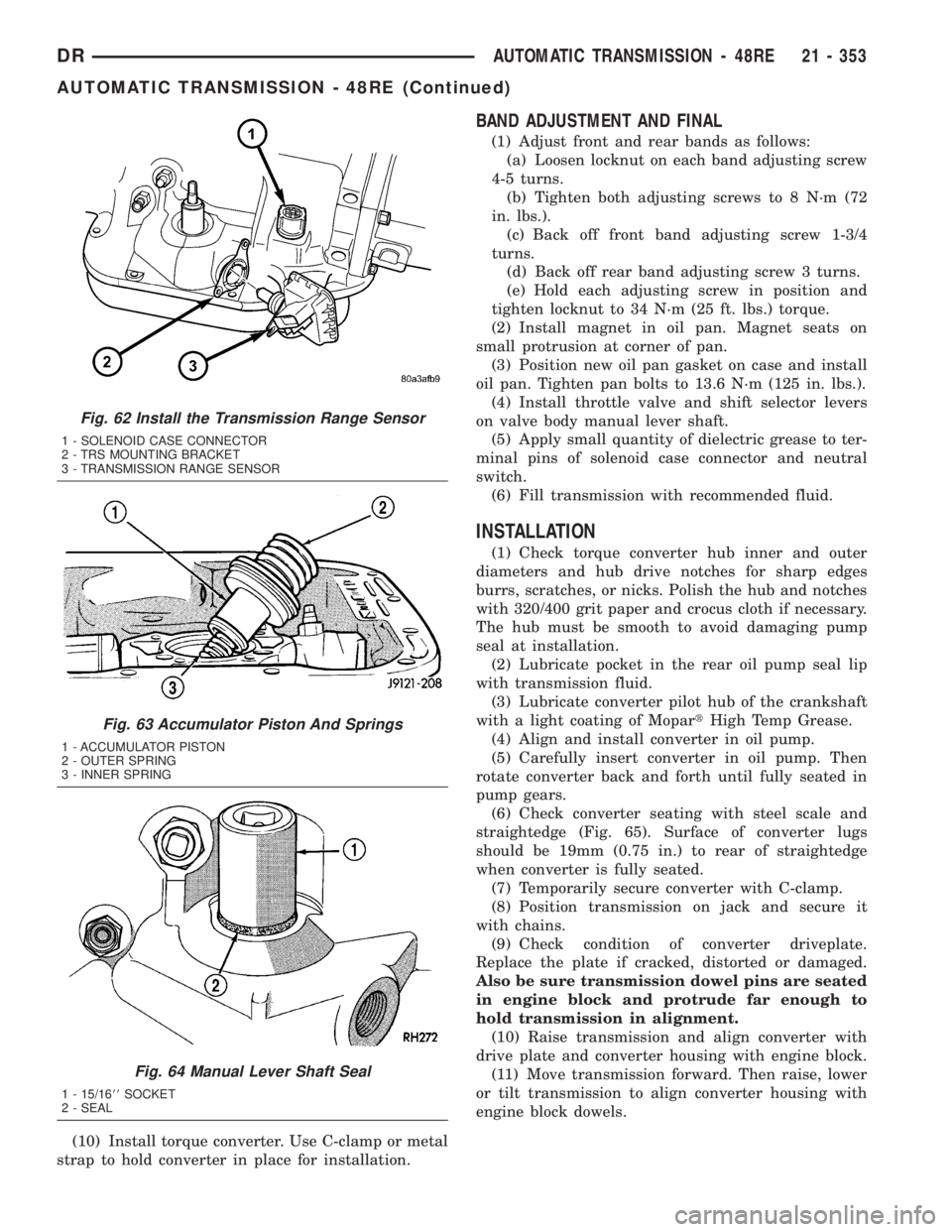
(10) Install torque converter. Use C-clamp or metal
strap to hold converter in place for installation.
BAND ADJUSTMENT AND FINAL
(1) Adjust front and rear bands as follows:
(a) Loosen locknut on each band adjusting screw
4-5 turns.
(b) Tighten both adjusting screws to 8 N´m (72
in. lbs.).
(c) Back off front band adjusting screw 1-3/4
turns.
(d) Back off rear band adjusting screw 3 turns.
(e) Hold each adjusting screw in position and
tighten locknut to 34 N´m (25 ft. lbs.) torque.
(2) Install magnet in oil pan. Magnet seats on
small protrusion at corner of pan.
(3) Position new oil pan gasket on case and install
oil pan. Tighten pan bolts to 13.6 N´m (125 in. lbs.).
(4) Install throttle valve and shift selector levers
on valve body manual lever shaft.
(5) Apply small quantity of dielectric grease to ter-
minal pins of solenoid case connector and neutral
switch.
(6) Fill transmission with recommended fluid.
INSTALLATION
(1) Check torque converter hub inner and outer
diameters and hub drive notches for sharp edges
burrs, scratches, or nicks. Polish the hub and notches
with 320/400 grit paper and crocus cloth if necessary.
The hub must be smooth to avoid damaging pump
seal at installation.
(2) Lubricate pocket in the rear oil pump seal lip
with transmission fluid.
(3) Lubricate converter pilot hub of the crankshaft
with a light coating of MopartHigh Temp Grease.
(4) Align and install converter in oil pump.
(5) Carefully insert converter in oil pump. Then
rotate converter back and forth until fully seated in
pump gears.
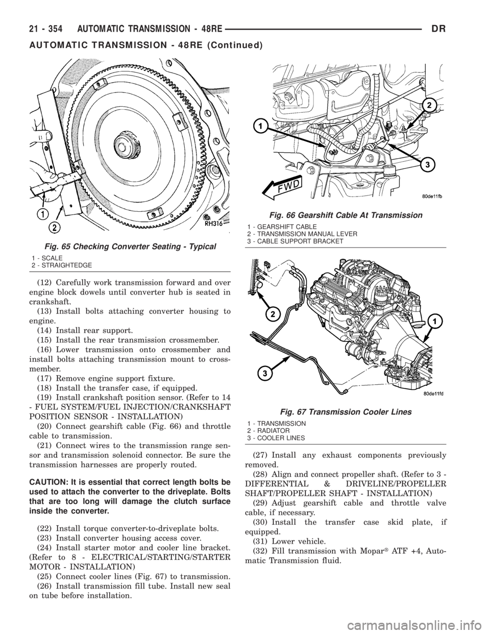
(6) Check converter seating with steel scale and
straightedge (Fig. 65). Surface of converter lugs
should be 19mm (0.75 in.) to rear of straightedge
when converter is fully seated.
(7) Temporarily secure converter with C-clamp.
(8) Position transmission on jack and secure it
with chains.
(9) Check condition of converter driveplate.
Replace the plate if cracked, distorted or damaged.
Also be sure transmission dowel pins are seated
in engine block and protrude far enough to
hold transmission in alignment.
(10) Raise transmission and align converter with
drive plate and converter housing with engine block.
(11) Move transmission forward. Then raise, lower
or tilt transmission to align converter housing with
engine block dowels.
Fig. 62 Install the Transmission Range Sensor
1 - SOLENOID CASE CONNECTOR
2 - TRS MOUNTING BRACKET
3 - TRANSMISSION RANGE SENSOR
Fig. 63 Accumulator Piston And Springs
1 - ACCUMULATOR PISTON
2 - OUTER SPRING
3 - INNER SPRING
Fig. 64 Manual Lever Shaft Seal
1 - 15/1688SOCKET
2 - SEAL
DRAUTOMATIC TRANSMISSION - 48RE 21 - 353
AUTOMATIC TRANSMISSION - 48RE (Continued)
Page 2193 of 2895
(12) Carefully work transmission forward and over
engine block dowels until converter hub is seated in
crankshaft.
(13) Install bolts attaching converter housing to
engine.
(14) Install rear support.
(15) Install the rear transmission crossmember.
(16) Lower transmission onto crossmember and
install bolts attaching transmission mount to cross-
member.
(17) Remove engine support fixture.
(18) Install the transfer case, if equipped.
(19) Install crankshaft position sensor. (Refer to 14
- FUEL SYSTEM/FUEL INJECTION/CRANKSHAFT
POSITION SENSOR - INSTALLATION)
(20) Connect gearshift cable (Fig. 66) and throttle
cable to transmission.
(21) Connect wires to the transmission range sen-
sor and transmission solenoid connector. Be sure the
transmission harnesses are properly routed.
CAUTION: It is essential that correct length bolts be
used to attach the converter to the driveplate. Bolts
that are too long will damage the clutch surface
inside the converter.
(22) Install torque converter-to-driveplate bolts.
(23) Install converter housing access cover.
(24) Install starter motor and cooler line bracket.
(Refer to 8 - ELECTRICAL/STARTING/STARTER
MOTOR - INSTALLATION)
(25) Connect cooler lines (Fig. 67) to transmission.
(26) Install transmission fill tube. Install new seal
on tube before installation.(27) Install any exhaust components previously
removed.
(28) Align and connect propeller shaft. (Refer to 3 -
DIFFERENTIAL & DRIVELINE/PROPELLER
SHAFT/PROPELLER SHAFT - INSTALLATION)
(29) Adjust gearshift cable and throttle valve
cable, if necessary.
(30) Install the transfer case skid plate, if
equipped.
(31) Lower vehicle.
(32) Fill transmission with MopartATF +4, Auto-
matic Transmission fluid.
Fig. 65 Checking Converter Seating - Typical
1 - SCALE
2 - STRAIGHTEDGE
Fig. 66 Gearshift Cable At Transmission
1 - GEARSHIFT CABLE
2 - TRANSMISSION MANUAL LEVER
3 - CABLE SUPPORT BRACKET
Fig. 67 Transmission Cooler Lines
1 - TRANSMISSION
2 - RADIATOR
3 - COOLER LINES
21 - 354 AUTOMATIC TRANSMISSION - 48REDR
AUTOMATIC TRANSMISSION - 48RE (Continued)
Page 2207 of 2895
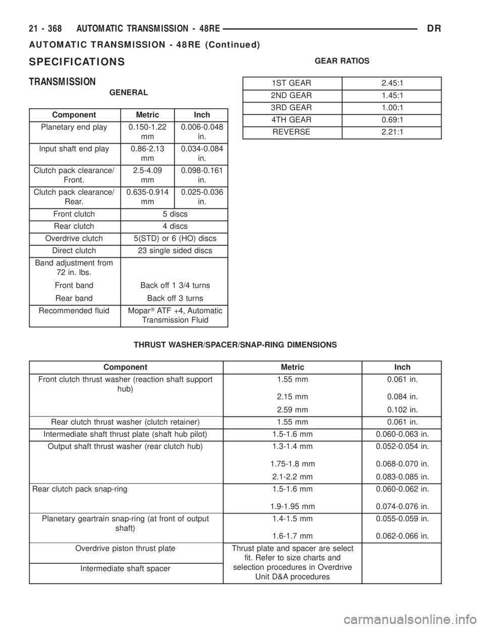
SPECIFICATIONS
TRANSMISSION
GENERAL
Component Metric Inch
Planetary end play 0.150-1.22
mm0.006-0.048
in.
Input shaft end play 0.86-2.13
mm0.034-0.084
in.
Clutch pack clearance/
Front.2.5-4.09
mm0.098-0.161
in.
Clutch pack clearance/
Rear.0.635-0.914
mm0.025-0.036
in.
Front clutch 5 discs
Rear clutch 4 discs
Overdrive clutch 5(STD) or 6 (HO) discs
Direct clutch 23 single sided discs
Band adjustment from
72 in. lbs.
Front band Back off 1 3/4 turns
Rear band Back off 3 turns
Recommended fluid MoparTATF +4, Automatic
Transmission FluidGEAR RATIOS
1ST GEAR 2.45:1
2ND GEAR 1.45:1
3RD GEAR 1.00:1
4TH GEAR 0.69:1
REVERSE 2.21:1
THRUST WASHER/SPACER/SNAP-RING DIMENSIONS
Component Metric Inch
Front clutch thrust washer (reaction shaft support
hub)1.55 mm 0.061 in.
2.15 mm 0.084 in.
2.59 mm 0.102 in.
Rear clutch thrust washer (clutch retainer) 1.55 mm 0.061 in.
Intermediate shaft thrust plate (shaft hub pilot) 1.5-1.6 mm 0.060-0.063 in.
Output shaft thrust washer (rear clutch hub) 1.3-1.4 mm 0.052-0.054 in.
1.75-1.8 mm 0.068-0.070 in.
2.1-2.2 mm 0.083-0.085 in.
Rear clutch pack snap-ring 1.5-1.6 mm 0.060-0.062 in.
1.9-1.95 mm 0.074-0.076 in.
Planetary geartrain snap-ring (at front of output
shaft)1.4-1.5 mm 0.055-0.059 in.
1.6-1.7 mm 0.062-0.066 in.
Overdrive piston thrust plate Thrust plate and spacer are select
fit. Refer to size charts and
selection procedures in Overdrive
Unit D&A procedures Intermediate shaft spacer
21 - 368 AUTOMATIC TRANSMISSION - 48REDR
AUTOMATIC TRANSMISSION - 48RE (Continued)
Page 2208 of 2895
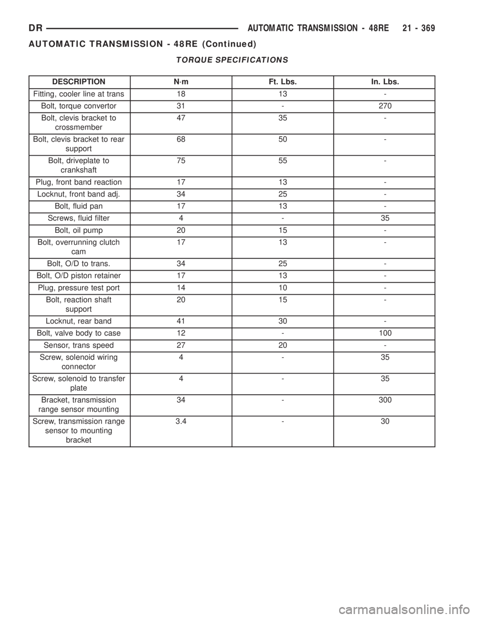
TORQUE SPECIFICATIONS
DESCRIPTION N´m Ft. Lbs. In. Lbs.
Fitting, cooler line at trans 18 13 -
Bolt, torque convertor 31 - 270
Bolt, clevis bracket to
crossmember47 35 -
Bolt, clevis bracket to rear
support68 50 -
Bolt, driveplate to
crankshaft75 55 -
Plug, front band reaction 17 13 -
Locknut, front band adj. 34 25 -
Bolt, fluid pan 17 13 -
Screws, fluid filter 4 - 35
Bolt, oil pump 20 15 -
Bolt, overrunning clutch
cam17 13 -
Bolt, O/D to trans. 34 25 -
Bolt, O/D piston retainer 17 13 -
Plug, pressure test port 14 10 -
Bolt, reaction shaft
support20 15 -
Locknut, rear band 41 30 -
Bolt, valve body to case 12 - 100
Sensor, trans speed 27 20 -
Screw, solenoid wiring
connector4-35
Screw, solenoid to transfer
plate4-35
Bracket, transmission
range sensor mounting34 - 300
Screw, transmission range
sensor to mounting
bracket3.4 - 30
DRAUTOMATIC TRANSMISSION - 48RE 21 - 369
AUTOMATIC TRANSMISSION - 48RE (Continued)