2003 DODGE RAM service indicator
[x] Cancel search: service indicatorPage 534 of 2895
reads from ª8º to ª18º volts. An International Control
and Display Symbol icon for ªBattery Charging Con-
ditionº is located on the cluster overlay, directly
below the right end of the gauge scale. The voltage
gauge graphics are black against a white field except
for a single red graduation at each end of the gauge
scale, making them clearly visible within the instru-
ment cluster in daylight. When illuminated from
behind by the panel lamps dimmer controlled cluster
illumination lighting with the exterior lamps turned
On, the black graphics appear blue and the red
graphics still appear red. The orange gauge needle is
internally illuminated. Gauge illumination is pro-
vided by replaceable incandescent bulb and bulb
holder units located on the instrument cluster elec-
tronic circuit board. The voltage gauge is serviced as
a unit with the instrument cluster.
OPERATION
The voltage gauge gives an indication to the vehi-
cle operator of the electrical system voltage. This
gauge is controlled by the instrument cluster circuit
board based upon cluster programming and elec-
tronic messages received by the cluster from the
Powertrain Control Module (PCM) on vehicles
equipped with a gasoline engine, or from the Engine
Control Module (ECM) on vehicles equipped with a
diesel engine over the Programmable Communica-
tions Interface (PCI) data bus. The voltage gauge is
an air core magnetic unit that receives battery cur-
rent on the instrument cluster electronic circuit
board through the fused ignition switch output (run-
start) circuit whenever the ignition switch is in the
On or Start positions. The cluster is programmed to
move the gauge needle back to the left end of the
scale after the ignition switch is turned to the Off
position. The instrument cluster circuitry controls
the gauge needle position and provides the following
features:
²System Voltage Message- Each time the clus-
ter receives a system voltage message from the PCM
or ECM indicating the system voltage is between
about 9.5 volts and about 15 volts, the gauge needle
is moved to the relative voltage position on the gauge
scale.
²System Voltage Low (Charge Fail) Message
- Each time the cluster receives three consecutive
messages from the PCM or ECM indicating the elec-
trical system voltage is less than about 9 volts
(charge fail condition), the gauge needle is moved to
the graduation on the far left end of the gauge scale
and the check gauges indicator is illuminated. The
gauge needle remains at the far left end of the gauge
scale and the check gauges indicator remains illumi-
nated until the cluster receives a single message
from the PCM or ECM indicating the electrical sys-tem voltage is greater than about 9.5 volts (but less
than about 15.5 volts), or until the ignition switch is
turned to the Off position, whichever occurs first. On
vehicles equipped with the optional diesel engine, the
ECM is programmed to restrict the voltage gauge
needle to a position above the graduation on the far
left end of the gauge scale and suppress the check
engine indicator operation until after the engine
intake manifold air heater has completed a pre-heat
or post-heat cycle.
²System Voltage High Message- Each time
the cluster receives three consecutive messages from
the PCM or ECM indicating the electrical system
voltage is greater than about 15.5 volts, the gauge
needle is moved to the graduation on the far right
end of the gauge scale and the check gauges indica-
tor is illuminated. The gauge needle remains at the
right end of the gauge scale and the check gauges
indicator remains illuminated until the cluster
receives a message from the PCM or ECM indicating
the electrical system voltage is less than about 15.0
volts (but greater than about 9.5 volts), or until the
ignition switch is turned to the Off position, which-
ever occurs first.
²Communication Error- If the cluster fails to
receive a system voltage message, it will hold the
gauge needle at the last indication for about five sec-
onds or until the ignition switch is turned to the Off
position, whichever occurs first. After five seconds,
the cluster will move the gauge needle to the far left
end of the gauge scale.
²Actuator Test- Each time the cluster is put
through the actuator test, the voltage gauge needle
will be swept to several calibration points on the
gauge scale in a prescribed sequence in order to con-
firm the functionality of the gauge and the cluster
control circuitry.
On vehicles with a gasoline engine, the PCM con-
tinually monitors the system voltage to control the
generator output. On vehicles with a diesel engine,
the ECM continually monitors the system voltage to
control the generator output. The PCM or ECM then
sends the proper system voltage messages to the
instrument cluster. For further diagnosis of the volt-
age gauge or the instrument cluster circuitry that
controls the gauge, (Refer to 8 - ELECTRICAL/IN-
STRUMENT CLUSTER - DIAGNOSIS AND TEST-
ING). If the instrument cluster turns on the check
gauges indicator due to a charge fail or voltage high
condition, it may indicate that the charging system
requires service. For proper diagnosis of the charging
system, the PCM, the ECM, the PCI data bus, or the
electronic message inputs to the instrument cluster
that control the voltage gauge, a DRBIIItscan tool is
required. Refer to the appropriate diagnostic infor-
mation.
DRINSTRUMENT CLUSTER 8J - 41
VOLTAGE GAUGE (Continued)
Page 535 of 2895

WAIT-TO-START INDICATOR
DESCRIPTION
A wait-to-start indicator is only found in the
instrument clusters for vehicles equipped with an
optional diesel engine. The wait-to-start indicator is
located near the lower edge of the instrument cluster,
between the tachometer and the speedometer. The
wait-to-start indicator consists of stencil-like cutout
of the International Control and Display Symbol icon
for ªDiesel Preheatº in the opaque layer of the instru-
ment cluster overlay. The dark outer layer of the
overlay prevents the indicator from being clearly vis-
ible when it is not illuminated. An amber Light
Emitting Diode (LED) behind the cutout in the
opaque layer of the overlay causes the icon to appear
in amber through the translucent outer layer of the
overlay when the indicator is illuminated from
behind by the LED, which is soldered onto the
instrument cluster electronic circuit board. The wait-
to-start indicator is serviced as a unit with the
instrument cluster.
OPERATION
The wait-to-start indicator gives an indication to
the vehicle operator when the air temperature within
the diesel engine intake manifold is too cool for effi-
cient and reliable engine starting, and that the
intake air heater grids are energized in their pre-
heat operating mode. This indicator is controlled by a
transistor on the instrument cluster circuit board
based upon cluster programming and electronic mes-
sages received by the cluster from the Engine Control
Module (ECM) over the Programmable Communica-
tions Interface (PCI) data bus. The wait-to-start indi-
cator Light Emitting Diode (LED) is completely
controlled by the instrument cluster logic circuit, and
that logic will only allow this indicator to operate
when the instrument cluster receives a battery cur-
rent input on the fused ignition switch output (run-
start) circuit. Therefore, the LED will always be off
when the ignition switch is in any position except On
or Start. The LED only illuminates when it is pro-
vided a path to ground by the instrument cluster
transistor. The instrument cluster will turn on the
wait-to-start indicator for the following reasons:
²Wait-To-Start Lamp-On Message- Each time
the cluster receives a wait-to-start lamp-on message
from the ECM indicating that the air temperature
within the intake manifold is too cool for efficient
and reliable engine starting, the wait-to-start indica-
tor will be illuminated. The indicator remains illumi-
nated until the cluster receives a wait-to-start lamp-
off message, until the ECM detects that the engine is
running or until the ignition switch is turned to the
Off position, whichever occurs first.²Actuator Test- Each time the cluster is put
through the actuator test, the wait-to-start indicator
will be turned on, then off again during the bulb
check portion of the test to confirm the functionality
of the LED and the cluster control circuitry.
The ECM continually monitors the engine intake
air temperature sensor to determine when the intake
air heater grids should be energized in their pre-heat
operating mode. The ECM then sends the proper
wait-to-start lamp-on and lamp-off messages to the
instrument cluster. For further diagnosis of the wait-
to-start indicator or the instrument cluster circuitry
that controls the indicator, (Refer to 8 - ELECTRI-
CAL/INSTRUMENT CLUSTER - DIAGNOSIS AND
TESTING). For proper diagnosis of the engine intake
air temperature sensor, the intake air heater grid
control circuits, the ECM, the PCI data bus, or the
electronic message inputs to the instrument cluster
that control the wait-to-start indicator, a DRBIIIt
scan tool is required. Refer to the appropriate diag-
nostic information.
WASHER FLUID INDICATOR
DESCRIPTION
A washer fluid indicator is standard equipment on
all instrument clusters. The washer fluid indicator
consists of the words ªLOW WASHº, which appear in
the lower portion of the odometer/trip odometer Vac-
uum-Fluorescent Display (VFD) unit. The VFD is sol-
dered onto the cluster electronic circuit board and is
visible through a window with a smoked clear lens
located on the lower edge of the tachometer gauge
dial face of the cluster overlay. The dark lens over
the VFD prevents the indicator from being clearly
visible when it is not illuminated. The ªLOW WASHº
text appears in an amber color and at the same light-
ing level as the odometer/trip odometer information
when it is illuminated by the instrument cluster elec-
tronic circuit board. The washer fluid indicator is ser-
viced as a unit with the VFD in the instrument
cluster.
OPERATION
The washer fluid indicator gives an indication to
the vehicle operator that the fluid level in the washer
reservoir is low. This indicator is controlled by the
instrument cluster circuit board based upon cluster
programming and electronic messages received by
the cluster from the Front Control Module (FCM)
over the Programmable Communications Interface
(PCI) data bus. The washer fluid indicator is com-
pletely controlled by the instrument cluster logic cir-
cuit, and that logic will only allow this indicator to
operate when the instrument cluster receives a bat-
8J - 42 INSTRUMENT CLUSTERDR
Page 536 of 2895
tery current input on the fused ignition switch out-
put (run-start) circuit. Therefore, the indicator will
always be off when the ignition switch is in any posi-
tion except On or Start. The indicator only illumi-
nates when it is switched to ground by the
instrument cluster circuitry. The instrument cluster
will turn on the washer fluid indicator for the follow-
ing reasons:
²Washer Fluid Indicator Lamp-On Message-
Each time the cluster receives a washer fluid indica-
tor lamp-on message from the FCM indicating that a
low washer condition has been detected for sixty con-
secutive seconds, the washer fluid indicator is illumi-
nated and a single chime tone is sounded. The
indicator remains illuminated until the cluster
receives a washer fluid indicator lamp-off message
for sixty consecutive seconds from the FCM or until
the ignition switch is turned to the Off position,
whichever occurs first. The chime tone feature will
only repeat during the same ignition cycle if the
washer fluid indicator is cycled off and then on again
by the appropriate washer fluid lamp messages from
the FCM.
²Actuator Test- Each time the cluster is put
through the actuator test, the washer fluid indicator
will be turned on, then off again during the VFD por-
tion of the test to confirm the functionality of the
VFD and the cluster control circuitry.
The FCM continually monitors the washer fluid
level switch in the washer reservoir to determine the
level of the washer fluid. The FCM then sends the
proper washer fluid indicator lamp-on and lamp-off
messages to the instrument cluster. For further diag-
nosis of the washer fluid indicator or the instrument
cluster circuitry that controls the indicator, (Refer to
8 - ELECTRICAL/INSTRUMENT CLUSTER - DIAG-
NOSIS AND TESTING). For proper diagnosis of the
washer fluid level switch, the FCM, the PCI data
bus, or the electronic message inputs to the instru-
ment cluster that control the washer fluid indicator,
a DRBIIItscan tool is required. Refer to the appro-
priate diagnostic information.WATER-IN-FUEL INDICATOR
DESCRIPTION
A water-in-fuel indicator is only found in the
instrument clusters for vehicles equipped with an
optional diesel engine. The water-in-fuel indicator is
located near the lower edge of the instrument cluster,
between the tachometer and the speedometer. The
water-in-fuel indicator consists of stencil-like cutout
of the International Control and Display Symbol icon
for ªWater In Fuelº in the opaque layer of the instru-
ment cluster overlay. The dark outer layer of the
overlay prevents the indicator from being clearly vis-
ible when it is not illuminated. A red Light Emitting
Diode (LED) behind the cutout in the opaque layer of
the overlay causes the icon to appear in red through
the translucent outer layer of the overlay when the
indicator is illuminated from behind by the LED,
which is soldered onto the instrument cluster elec-
tronic circuit board. The water-in-fuel indicator is
serviced as a unit with the instrument cluster.
OPERATION
The water-in-fuel indicator gives an indication to
the vehicle operator when there is excessive water in
the fuel system. This indicator is controlled by a
transistor on the instrument cluster circuit board
based upon the cluster programming and electronic
messages received by the cluster from the Engine
Control Module (ECM) over the Programmable Com-
munications Interface (PCI) data bus. The water-in-
fuel indicator Light Emitting Diode (LED) is
completely controlled by the instrument cluster logic
circuit, and that logic will only allow this indicator to
operate when the instrument cluster receives a bat-
tery current input on the fused ignition switch out-
put (run-start) circuit. Therefore, the LED will
always be off when the ignition switch is in any posi-
tion except On or Start. The LED only illuminates
when it is provided a path to ground by the instru-
ment cluster transistor. The instrument cluster will
turn on the water-in-fuel indicator for the following
reasons:
DRINSTRUMENT CLUSTER 8J - 43
WASHER FLUID INDICATOR (Continued)
Page 550 of 2895

(3) Resistance between terminals 85 and 86 (elec-
tromagnet) should be 75 8 ohms. If OK, go to Step
4. If not OK, replace the faulty relay.
(4) Connect a battery to terminals 85 and 86.
There should now be continuity between terminals
30 and 87, and no continuity between terminals 87A
and 30. If OK, reinstall the relay and use a DRBIIIt
scan tool to perform further testing. Refer to the
appropriate diagnostic information.
REMOVAL
WARNING: ON VEHICLES EQUIPPED WITH AIR-
BAGS, DISABLE THE SUPPLEMENTAL RESTRAINT
SYSTEM BEFORE ATTEMPTING ANY STEERING
WHEEL, STEERING COLUMN, DRIVER AIRBAG,
PASSENGER AIRBAG, SEAT BELT TENSIONER,
FRONT IMPACT SENSORS, SIDE CURTAIN AIRBAG,
OR INSTRUMENT PANEL COMPONENT DIAGNOSIS
OR SERVICE. DISCONNECT AND ISOLATE THE
BATTERY NEGATIVE (GROUND) CABLE, THEN
WAIT TWO MINUTES FOR THE SYSTEM CAPACI-
TOR TO DISCHARGE BEFORE PERFORMING FUR-
THER DIAGNOSIS OR SERVICE. THIS IS THE ONLY
SURE WAY TO DISABLE THE SUPPLEMENTAL
RESTRAINT SYSTEM. FAILURE TO TAKE THE
PROPER PRECAUTIONS COULD RESULT IN ACCI-
DENTAL AIRBAG DEPLOYMENT AND POSSIBLE
PERSONAL INJURY.
(1) Disconnect and isolate the battery negative
cable.
(2) Remove the cover for the Power Distribution
Center (PDC).
(3) Remove the front fog lamp relay by grasping it
firmly and pulling it straight out from the receptacle
in the PDC.
INSTALLATION
WARNING: ON VEHICLES EQUIPPED WITH AIR-
BAGS, DISABLE THE SUPPLEMENTAL RESTRAINT
SYSTEM BEFORE ATTEMPTING ANY STEERING
WHEEL, STEERING COLUMN, DRIVER AIRBAG,
PASSENGER AIRBAG, SEAT BELT TENSIONER,
FRONT IMPACT SENSORS, SIDE CURTAIN AIRBAG,
OR INSTRUMENT PANEL COMPONENT DIAGNOSIS
OR SERVICE. DISCONNECT AND ISOLATE THE
BATTERY NEGATIVE (GROUND) CABLE, THEN
WAIT TWO MINUTES FOR THE SYSTEM CAPACI-
TOR TO DISCHARGE BEFORE PERFORMING FUR-
THER DIAGNOSIS OR SERVICE. THIS IS THE ONLY
SURE WAY TO DISABLE THE SUPPLEMENTAL
RESTRAINT SYSTEM. FAILURE TO TAKE THE
PROPER PRECAUTIONS COULD RESULT IN ACCI-
DENTAL AIRBAG DEPLOYMENT AND POSSIBLE
PERSONAL INJURY.(1) Position the front fog lamp relay to the proper
receptacle in the Power Distribution Center (PDC).
(2) Align the front fog lamp relay terminals with
the terminal cavities in the PDC.
(3) Press firmly and evenly on the top of the front
fog lamp relay until the terminals are fully seated in
the PDC.
(4) Reconnect the battery negative cable.
HAZARD SWITCH
DESCRIPTION
The hazard switch is activated by a push button
located in the multifunction switch on the top of the
steering column between the steering wheel and
instrument cluster.
The hazard warning system allows the vehicle
operator to provide other vehicle operators in the
near proximity an optical indication that the vehicle
is disabled or an obstacle to traffic flow. The hazard
warning system has battery voltage at all times,
regardless of ignition position.
OPERATION
The instrument cluster monitors the multiplexed
multifunction switch operation. When the hazard
warning switch is activated, the instrument cluster
will send a J1850 bus message to the Front Control
Module (FCM), then activate the two turn signal indi-
cators and audible click in the instrument cluster.
The FCM will then activate the necessary relays in
the Power Distribution Center (PDC) to begin flash-
ing both the front and rear turn signal indicator
lamps.
HEADLAMP
REMOVAL
(1) Disconnect and isolate the negitive battery
cable.
(2) Remove the headlamp unit (Refer to 8 - ELEC-
TRICAL/LAMPS/LIGHTING - EXTERIOR/HEAD-
LAMP UNIT - REMOVAL).
(3) Seperate the socket from the headlamp unit.
INSTALLATION
CAUTION: Do Not Touch the bulb glass with fingers
or other oily surfaces. Reduced bulb life will result.
(1) Install the socket into the headlamp unit.
(2) Install the headlamp unit (Refer to 8 - ELEC-
TRICAL/LAMPS/LIGHTING - EXTERIOR/HEAD-
LAMP UNIT - INSTALLATION).
(3) Connect the negitive battery cable.
DRLAMPS/LIGHTING - EXTERIOR 8L - 13
FOG LAMP RELAY (Continued)
Page 551 of 2895
HEADLAMP SWITCH
DESCRIPTION
The multiplexed headlamp switch is located on the
instrument panel. The headlamp switch controls the
parking lamps, fog lamps and the headlamps. A sep-
arate switch in the module controls the interior
lamps and instrument cluster illumination. This
switch also contains a rheostat for controlling the
illumination level of the cluster lamps.
OPERATION
The multiplexed headlamp switch has an off, park-
ing lamp, fog lamp and a headlamp on position. High
beams are controlled by the multiplexed multifunc-
tion switch on the steering column. The fog lamps
are illuminated by pulling back on the headlamp
switch knob when in the parking lamp or headlamp
ON position.The headlamp switch cannot be
repaired. It must be replaced.
The Instrument Cluster monitors the headlamp
and multifunction switch operation. When the head-
lamp switch is rotated to the parking lamp or On
position the Instrument Cluster sends a J1850 mes-
sage to the Front Control Module, which is mated to
the power distribution center to become the Inte-
grated Control Module, to illuminate the appropriate
bulbs. When the multifunction switch is activated to
the optical horn or high beam position the Instru-
ment Cluster illuminates the high beam indicator
and sends a J1850 message to the Front Control
Module to illuminate the appropriate bulbs.
REMOVAL
WARNING: ON VEHICLES EQUIPPED WITH AIR-
BAGS, DISABLE THE AIRBAG SYSTEM BEFORE
ATTEMPTING ANY STEERING WHEEL, STEERING
COLUMN, OR INSTRUMENT PANEL COMPONENT
DIAGNOSIS OR SERVICE. DISCONNECT AND ISO-
LATE THE BATTERY NEGATIVE (GROUND) CABLE,
THEN WAIT TWO MINUTES FOR THE AIRBAG SYS-
TEM CAPACITOR TO DISCHARGE BEFORE PER-
FORMING FURTHER DIAGNOSIS OR SERVICE. THIS
IS THE ONLY SURE WAY TO DISABLE THE AIRBAG
SYSTEM. FAILURE TO TAKE THE PROPER PRE-
CAUTIONS COULD RESULT IN ACCIDENTAL AIR-
BAG DEPLOYMENT AND POSSIBLE PERSONAL
INJURY.
(1) Disconnect and isolate the battery negative
cable.
(2) Remove the left instrument panel bezel. (Refer
to 23 - BODY/INSTRUMENT PANEL/CLUSTER
BEZEL - REMOVAL).
(3) Disconnect the harness connector.(4) Remove the screws that secure the headlamp
switch to the instrument panel bezel (Fig. 9).
(5) Remove the headlamp switch from the instru-
ment panel bezel.
INSTALLATION
WARNING: ON VEHICLES EQUIPPED WITH AIR-
BAGS, DISABLE THE AIRBAG SYSTEM BEFORE
ATTEMPTING ANY STEERING WHEEL, STEERING
COLUMN, OR INSTRUMENT PANEL COMPONENT
DIAGNOSIS OR SERVICE. DISCONNECT AND ISO-
LATE THE BATTERY NEGATIVE (GROUND) CABLE,
THEN WAIT TWO MINUTES FOR THE AIRBAG SYS-
TEM CAPACITOR TO DISCHARGE BEFORE PER-
FORMING FURTHER DIAGNOSIS OR SERVICE. THIS
IS THE ONLY SURE WAY TO DISABLE THE AIRBAG
SYSTEM. FAILURE TO TAKE THE PROPER PRE-
CAUTIONS COULD RESULT IN ACCIDENTAL AIR-
BAG DEPLOYMENT AND POSSIBLE PERSONAL
INJURY.
(1) Position the headlamp switch to the left instru-
ment panel bezal and secure with screws.Tighten the
screws to 2.2 N´m (20 in. lbs.).
(2) Reconnect the instrument panel wire harness
connector for the headlamp switch.
(3) Position the left instrument panel bezal on to
the instrument panel.
Fig. 9 Headlamp Switch Removal
1 - DASH BOARD
2 - HEADLAMP SWITCH
3 - INSTRUMENT PANEL BEZAL
8L - 14 LAMPS/LIGHTING - EXTERIORDR
Page 555 of 2895
lobe, pushing on the cancel actuator, returns the
switch to the OFF position.
OPERATION - TURN SIGNAL SYSTEM
The Instrument Cluster monitors the multiplexed
multifunction switch. In a turning event the Instru-
ment Cluster senses a change in the turn signal
lever and illuminates the appropriate turn signal
indicator. At the same time, the Instrument Cluster
will send a J1850 message on the PCI bus to the
Front Control Module (FCM). The FCM will respond
by activating the appropriate relay in the Power Dis-
tribution Center.
A chime will sound after the turn is completed if
vehicle has traveled a distance of approximately 1.0
mile and a speed of 15 mph, with the turn signal ON.
DIAGNOSIS AND TESTING - MULTI-FUNCTION
SWITCH
To test the turn signal, headlamp beam select and
optical horn portion of the multi-function switch:
(1) Remove the multi-function switch, refer to
Electrical, Lamps/Lighting - Exterior, Multi-Function
Switch, Removal, and Installation.
(2) Using an ohmmeter check the resistance read-
ings between multi-function switch pins. Refer to
Wiring Diagrams for proper pin numbers and the
MULTI-FUNCTION SWITCH TESTS table.
MULTI-FUNCTION SWITCH TESTS
EXTERIOR LIGHTING FUNCTIONS
SWITCH POSITION CONNECTOR PINS RESISTANCE (OHMS)
Off 1 - 2 Open
Headlamp High Beams On 1 - 2 518 - 575
Hazard 3 - 2 115 - 128
Optical Horn (Flash-to-Pass) On 1 - 2 1257 - 1397
Off 3 - 2 2643 - 2937
Turn Signal Left 3 - 2 345 - 384
Turn Signal Right 3 - 2 786 - 873
FRONT WIPER FUNCTIONS
SWITCH POSITION CONNECTOR PINS RESISTANCE (OHMS) 10%
Front Wiper Off 2 - 4 6910 - 7678
Delay 1 2 - 4 2128 - 2365
Delay 2 2 - 4 1089 - 1210
Delay 3 2 - 4 627 - 697
Delay 4 2 - 4 388 - 431
Delay 5 2 - 4 234 - 261
Front Wiper Low 2 - 4 125 - 140
Front Wiper High 2 - 4 50 - 56
Wash 1 - 2 2584 - 2871
REMOVAL
WARNING: BEFORE SERVICING THE STEERING
COLUMN THE AIRBAG SYSTEM MUST BE DIS-
ARMED. REFER TO THE ELECTRICAL RESTRAINT
SYSTEM FOR SERVICE PROCEDURES. FAILURE
TO DO SO MAY RESULT IN ACCIDENTAL DEPLOY-
MENT OF THE AIRBAG AND POSSIBLE PERSONAL
INJURY(1) Disconnect and isolate battery negative cable.
(2) Remove the steering wheel and the upper and
lower steering column shrouds. Refer to Steering,
Column, Shroud, Removal.
(3) Disconnect the wire connector from the back of
the multi-function switch.
(4) Remove the screws retaining the multi-function
switch to the steering column adapter collar (Fig. 15).
(5) Remove the multi-function switch.
8L - 18 LAMPS/LIGHTING - EXTERIORDR
MULTI-FUNCTION SWITCH (Continued)
Page 604 of 2895
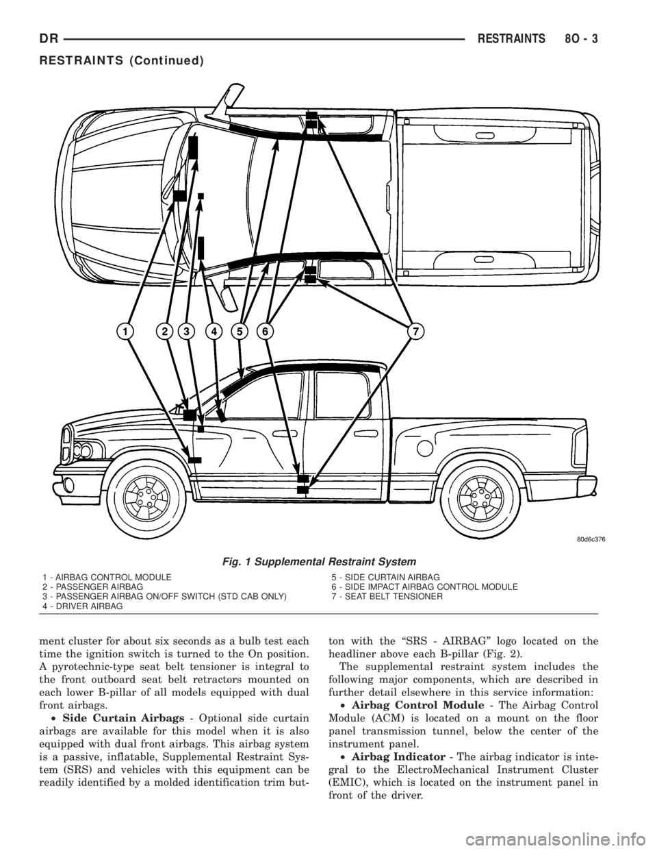
ment cluster for about six seconds as a bulb test each
time the ignition switch is turned to the On position.
A pyrotechnic-type seat belt tensioner is integral to
the front outboard seat belt retractors mounted on
each lower B-pillar of all models equipped with dual
front airbags.
²Side Curtain Airbags- Optional side curtain
airbags are available for this model when it is also
equipped with dual front airbags. This airbag system
is a passive, inflatable, Supplemental Restraint Sys-
tem (SRS) and vehicles with this equipment can be
readily identified by a molded identification trim but-ton with the ªSRS - AIRBAGº logo located on the
headliner above each B-pillar (Fig. 2).
The supplemental restraint system includes the
following major components, which are described in
further detail elsewhere in this service information:
²Airbag Control Module- The Airbag Control
Module (ACM) is located on a mount on the floor
panel transmission tunnel, below the center of the
instrument panel.
²Airbag Indicator- The airbag indicator is inte-
gral to the ElectroMechanical Instrument Cluster
(EMIC), which is located on the instrument panel in
front of the driver.
Fig. 1 Supplemental Restraint System
1 - AIRBAG CONTROL MODULE
2 - PASSENGER AIRBAG
3 - PASSENGER AIRBAG ON/OFF SWITCH (STD CAB ONLY)
4 - DRIVER AIRBAG5 - SIDE CURTAIN AIRBAG
6 - SIDE IMPACT AIRBAG CONTROL MODULE
7 - SEAT BELT TENSIONER
DRRESTRAINTS 8O - 3
RESTRAINTS (Continued)
Page 606 of 2895

Impact Airbag Control Modules (SIACM). An airbag
indicator in the ElectroMechanical Instrument Clus-
ter (EMIC) illuminates for about six seconds as a
bulb test each time the ignition switch is turned to
the On or Start positions. Following the bulb test,
the airbag indicator is turned on or off by the ACM
to indicate the status of the supplemental restraint
system. If the airbag indicator comes on at any time
other than during the bulb test, it indicates that
there is a problem in the supplemental restraint sys-
tem electrical circuits. Such a problem may cause air-
bags not to deploy when required, or to deploy when
not required.
Deployment of the supplemental restraints
depends upon the angle and severity of an impact.
Deployment is not based upon vehicle speed; rather,
deployment is based upon the rate of deceleration as
measured by the forces of gravity (G force) upon the
impact sensors. When an impact is severe enough,
the microprocessor in the ACM or the SIACM signals
the inflator of the appropriate airbag units to deploy
their airbag cushions. The outboard front seat belt
tensioners are provided with a deployment signal by
the ACM in conjunction with the driver and passen-
ger airbags. During a frontal vehicle impact, the
knee blockers work in concert with properly fastened
and adjusted seat belts to restrain both the driver
and the front seat passenger in the proper position
for an airbag deployment. The knee blockers also
absorb and distribute the crash energy from the
driver and the front seat passenger to the structure
of the instrument panel. The seat belt tensioner
removes the slack from the outboard front seat belts
to provide further assurance that the driver and
front seat passenger are properly positioned and
restrained for an airbag deployment.
Typically, the vehicle occupants recall more about
the events preceding and following a collision than
they do of an airbag deployment itself. This is
because the airbag deployment and deflation occur so
rapidly. In a typical 48 kilometer-per-hour (30 mile-
per-hour) barrier impact, from the moment of impact
until the airbags are fully inflated takes about 40
milliseconds. Within one to two seconds from the
moment of impact, the airbags are almost entirely
deflated. The times cited for these events are approx-
imations, which apply only to a barrier impact at the
given speed. Actual times will vary somewhat,
depending upon the vehicle speed, impact angle,
severity of the impact, and the type of collision.When the ACM monitors a problem in any of the
dual front airbag system circuits or components,
including the seat belt tensioners, it stores a fault
code or Diagnostic Trouble Code (DTC) in its memory
circuit and sends an electronic message to the EMIC
to turn on the airbag indicator. When the SIACM
monitors a problem in any of the side curtain airbag
system circuits or component, it stores a fault code or
DTC in its memory circuit and sends an electronic
message to the ACM, and the ACM sends an elec-
tronic message to the EMIC to turn on the airbag
indicator. Proper testing of the supplemental
restraint system components, the Programmable
Communications Interface (PCI) data bus, the elec-
tronic message inputs to and outputs from the EMIC,
the SIACM, or the ACM, as well as the retrieval or
erasure of a DTC from the ACM, SIACM, or EMIC
requires the use of a DRBIIItscan tool. Refer to the
appropriate diagnostic information.
See the owner's manual in the vehicle glove box for
more information on the features, use and operation
of all of the factory-installed passive restraints.
WARNING
WARNINGS - RESTRAINT SYSTEM
WARNING: DURING AND FOLLOWING ANY SEAT
BELT OR CHILD RESTRAINT ANCHOR SERVICE,
CAREFULLY INSPECT ALL SEAT BELTS, BUCKLES,
MOUNTING HARDWARE, RETRACTORS, TETHER
STRAPS, AND ANCHORS FOR PROPER INSTALLA-
TION, OPERATION, OR DAMAGE. REPLACE ANY
BELT THAT IS CUT, FRAYED, OR TORN.
STRAIGHTEN ANY BELT THAT IS TWISTED.
TIGHTEN ANY LOOSE FASTENERS. REPLACE ANY
BELT THAT HAS A DAMAGED OR INOPERATIVE
BUCKLE OR RETRACTOR. REPLACE ANY BELT
THAT HAS A BENT OR DAMAGED LATCH PLATE
OR ANCHOR PLATE. REPLACE ANY CHILD
RESTRAINT ANCHOR OR THE UNIT TO WHICH THE
ANCHOR IS INTEGRAL THAT HAS BEEN BENT OR
DAMAGED. NEVER ATTEMPT TO REPAIR A SEAT
BELT OR CHILD RESTRAINT COMPONENT.
ALWAYS REPLACE DAMAGED OR FAULTY SEAT
BELT AND CHILD RESTRAINT COMPONENTS WITH
THE CORRECT, NEW AND UNUSED REPLACEMENT
PARTS LISTED IN THE DAIMLERCHRYSLER MOPAR
PARTS CATALOG.
DRRESTRAINTS 8O - 5
RESTRAINTS (Continued)