2003 DODGE RAM battery replacement
[x] Cancel search: battery replacementPage 1576 of 2895
(11) Install the flywheel housing and bolts. Torque
bolts to 77 N´m (57 ft. lbs.).
(12) Install the flywheel or converter drive plate.
Tighten bolts to 137 N´m (101 ft. lbs.).
(13) Install the starter motor and torque to 43 N´m
(21 ft. lbs.)(Refer to 8 - ELECTRICAL/STARTING/
STARTER MOTOR - INSTALLATION).
(14) Install the transmission and transfer case (if
equipped).
(15) Lower vehicle.
(16) Fill the crankcase with new engine oil.
(17) Connect the battery negative cables.
(18) Start engine and check for oil leaks.
SOLID LIFTERS/TAPPETS
REMOVAL
NOTE: This procedure requires use of Miller Tool
8502 Tappet Replacement Kit.
(1) Remove camshaft (Refer to 9 - ENGINE/EN-
GINE BLOCK/CAMSHAFT & BEARINGS (IN
BLOCK) - REMOVAL).
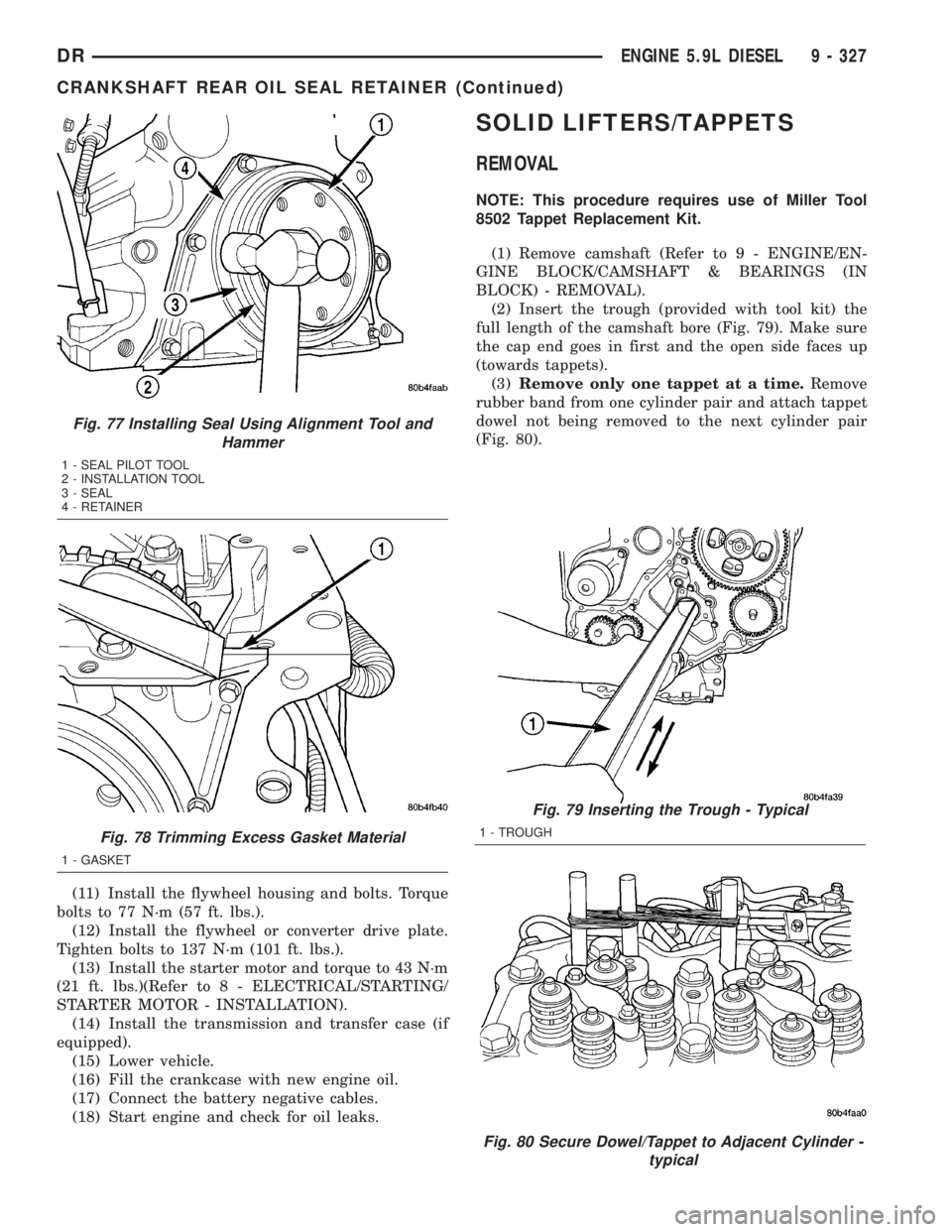
(2) Insert the trough (provided with tool kit) the
full length of the camshaft bore (Fig. 79). Make sure
the cap end goes in first and the open side faces up
(towards tappets).
(3)Remove only one tappet at a time.Remove
rubber band from one cylinder pair and attach tappet
dowel not being removed to the next cylinder pair
(Fig. 80).
Fig. 79 Inserting the Trough - Typical
1 - TROUGH
Fig. 80 Secure Dowel/Tappet to Adjacent Cylinder -
typical
Fig. 77 Installing Seal Using Alignment Tool and
Hammer
1 - SEAL PILOT TOOL
2 - INSTALLATION TOOL
3 - SEAL
4 - RETAINER
Fig. 78 Trimming Excess Gasket Material
1 - GASKET
DRENGINE 5.9L DIESEL 9 - 327
CRANKSHAFT REAR OIL SEAL RETAINER (Continued)
Page 1676 of 2895
CAUTION: Do not reuse damaged fasteners, quality
of repair would be suspect. Failure to use only pro-
duction fasteners or fasteners of equivalent hard-
ness can result in loosening or failure. Do not drill
any holes in the frame that are not specifically out-
lined in this or other, DaimlerChrysler procedure as
frame rail failure can result. When using heat to
straighten frame components do not exceed 566ÉC
(1050ÉF), metal fatigue can result.
NOTE: Procedures for 4X2 and 4X4 are common
except as noted in this procedure.
(1) Disconnect and isolate the battery negative
cable.
(2) Remove the front wheelhouse splash shield.
(Refer to 23 - BODY/EXTERIOR/FRONT WHEEL-
HOUSE SPLASH SHIELD - REMOVAL)
(3) Remove the bolts and position aside the wire
harness and grounds, if required.
(4) Remove the front bumper. (Refer to 13 -
FRAME & BUMPERS/BUMPERS/FRONT BUMPER
- REMOVAL)
(5) Loosen and lower the stabilizer bar mount and
bar. (Refer to 2 - SUSPENSION/FRONT/STABI-
LIZER BAR - REMOVAL)
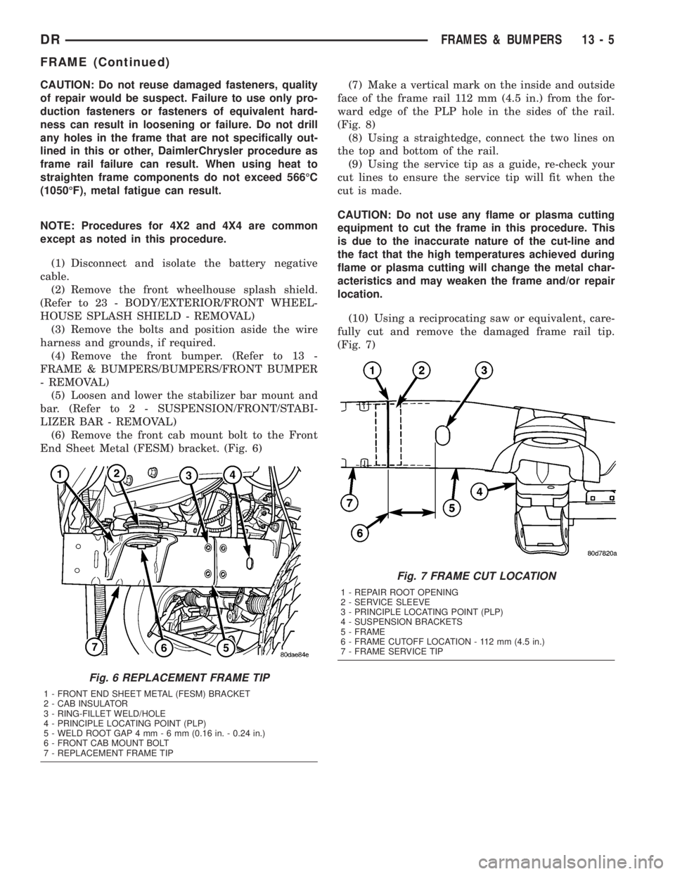
(6) Remove the front cab mount bolt to the Front
End Sheet Metal (FESM) bracket. (Fig. 6)(7) Make a vertical mark on the inside and outside
face of the frame rail 112 mm (4.5 in.) from the for-
ward edge of the PLP hole in the sides of the rail.
(Fig. 8)
(8) Using a straightedge, connect the two lines on
the top and bottom of the rail.
(9) Using the service tip as a guide, re-check your
cut lines to ensure the service tip will fit when the
cut is made.
CAUTION: Do not use any flame or plasma cutting
equipment to cut the frame in this procedure. This
is due to the inaccurate nature of the cut-line and
the fact that the high temperatures achieved during
flame or plasma cutting will change the metal char-
acteristics and may weaken the frame and/or repair
location.
(10) Using a reciprocating saw or equivalent, care-
fully cut and remove the damaged frame rail tip.
(Fig. 7)
Fig. 6 REPLACEMENT FRAME TIP
1 - FRONT END SHEET METAL (FESM) BRACKET
2 - CAB INSULATOR
3 - RING-FILLET WELD/HOLE
4 - PRINCIPLE LOCATING POINT (PLP)
5 - WELD ROOT GAP 4 mm-6mm(0.16 in. - 0.24 in.)
6 - FRONT CAB MOUNT BOLT
7 - REPLACEMENT FRAME TIP
Fig. 7 FRAME CUT LOCATION
1 - REPAIR ROOT OPENING
2 - SERVICE SLEEVE
3 - PRINCIPLE LOCATING POINT (PLP)
4 - SUSPENSION BRACKETS
5 - FRAME
6 - FRAME CUTOFF LOCATION - 112 mm (4.5 in.)
7 - FRAME SERVICE TIP
DRFRAMES & BUMPERS 13 - 5
FRAME (Continued)
Page 1686 of 2895
STANDARD PROCEDURE - REAR FRAME
H-SECTION REPLACEMENT
SAFETY PRECAUTIONS AND WARNINGS
WARNING: USE EYE PROTECTION WHEN GRIND-
ING OR WELDING METAL, SERIOUS EYE INJURY
CAN RESULT.
²BEFORE PROCEEDING WITH FRAME REPAIR
INVOLVING GRINDING OR WELDING, VERIFY THAT
VEHICLE FUEL SYSTEM IS NOT LEAKING OR IN
CONTACT WITH REPAIR AREA, PERSONAL INJURY
CAN RESULT.
²DO NOT ALLOW OPEN FLAME OR HEAT AND
METAL SPATTER FROM ARC WELDING, TO CON-
TACT PLASTIC BODY PANELS. FIRE OR EXPLO-
SION CAN RESULT.
²WHEN WELDED FRAME COMPONENTS ARE
REPLACED, ENSURE COMPLETE PENETRATION
WELD IS ACHIEVED DURING INSTALLATION. IF
NOT, DANGEROUS OPERATING CONDITIONS CAN
RESULT.
²STAND CLEAR OF CABLES OR CHAINS ON
PULLING EQUIPMENT DURING FRAME STRAIGHT-
ENING OPERATIONS, PERSONAL INJURY CAN
RESULT.
²DO NOT VENTURE UNDER A HOISTED VEHI-
CLE THAT IS NOT SUPPORTED ON SAFETY
STANDS, PERSONAL INJURY CAN RESULT.
CAUTION: Do not reuse damaged fasteners, quality
of repair would be suspect. Failure to use only pro-
duction fasteners or fasteners of equivalent hard-
ness can result in loosening or failure. Do not drill
holes in top or bottom frame rail flanges, frame rail
failure can result. When using heat to straighten
frame components do not exceed 566ÉC (1050ÉF),
metal fatigue can result.
CAUTION: This procedure is designed to replace
the H-section/spare tire support located at the rear
of the frame assembly. Prior to any cutting, the
vehicle must be mounted on the appropriate frame
repair equipment (ªframe rackº), checked with three
dimensional measuring equipment, and the neces-
sary pull corrections made. If damage remains in
the frame beyond the area covered by this service
part after the pull, the frame must be replaced in its
entirety.
(1) Disconnect and isolate the battery negative
cable.
(2) Remove the cargo box. (Refer to 23 - BODY/EX-
TERIOR/CARGO BOX - REMOVAL)(3) Remove the trailer hitch. (Refer to 13 - FRAME
& BUMPERS/FRAME/TRAILER HITCH -
REMOVAL)
(4) Raise and support the frame so the tires are off
floor.
(5) Remove the shock absorbers. (Refer to 2 - SUS-
PENSION/REAR/SHOCK - REMOVAL)
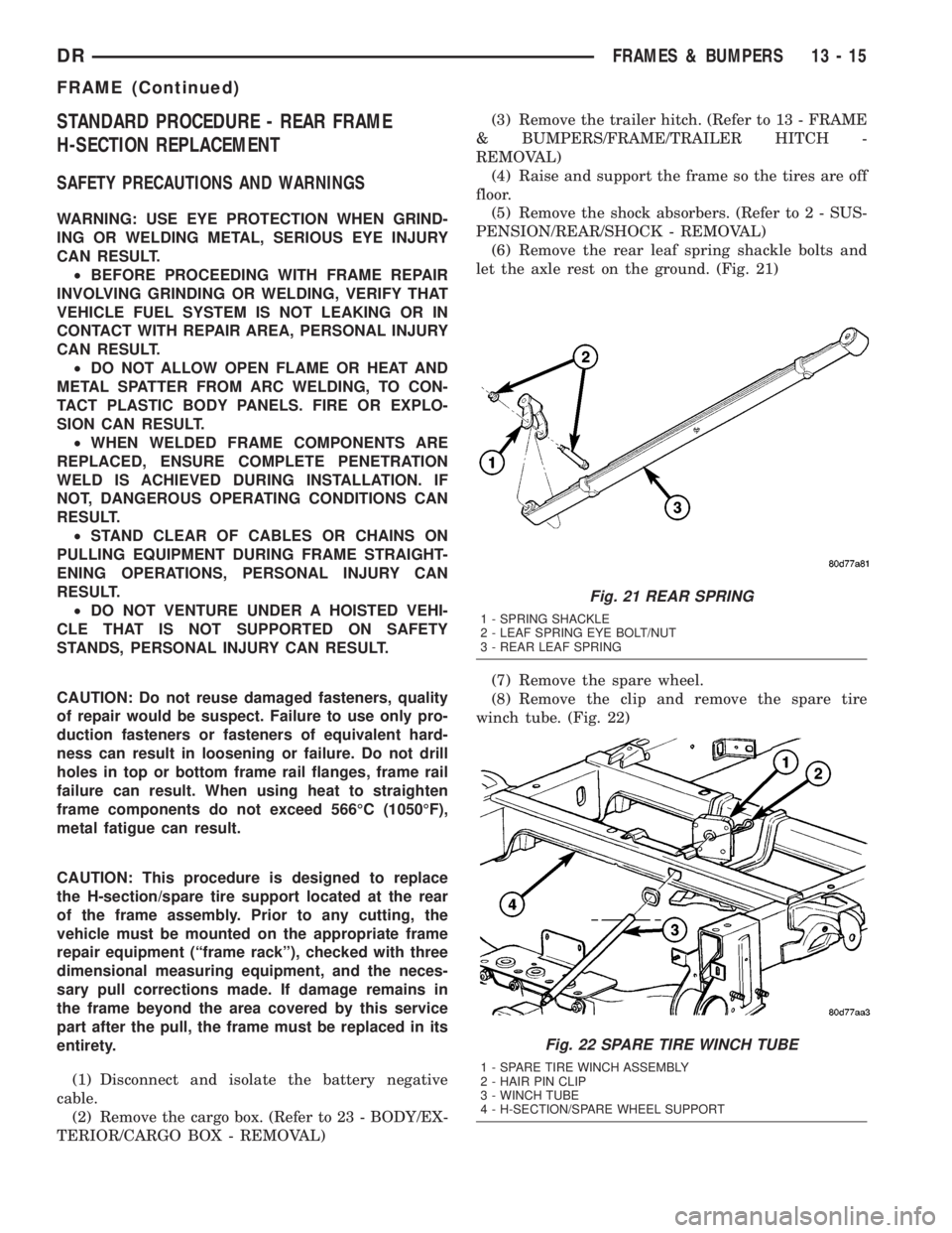
(6) Remove the rear leaf spring shackle bolts and
let the axle rest on the ground. (Fig. 21)
(7) Remove the spare wheel.
(8) Remove the clip and remove the spare tire
winch tube. (Fig. 22)
Fig. 21 REAR SPRING
1 - SPRING SHACKLE
2 - LEAF SPRING EYE BOLT/NUT
3 - REAR LEAF SPRING
Fig. 22 SPARE TIRE WINCH TUBE
1 - SPARE TIRE WINCH ASSEMBLY
2 - HAIR PIN CLIP
3 - WINCH TUBE
4 - H-SECTION/SPARE WHEEL SUPPORT
DRFRAMES & BUMPERS 13 - 15
FRAME (Continued)
Page 1687 of 2895
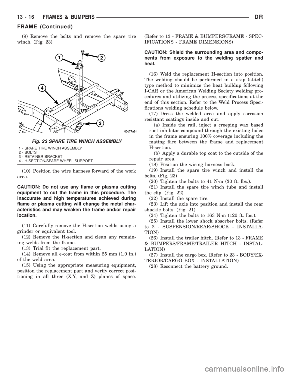
(9) Remove the bolts and remove the spare tire
winch. (Fig. 23)
(10) Position the wire harness forward of the work
area.
CAUTION: Do not use any flame or plasma cutting
equipment to cut the frame in this procedure. The
inaccurate and high temperatures achieved during
flame or plasma cutting will change the metal char-
acteristics and may weaken the frame and/or repair
location.
(11) Carefully remove the H-section welds using a
grinder or equivalent tool.
(12) Remove the H-section and clean any remain-
ing welds from the frame.
(13) Trial fit the replacement part.
(14) Remove all e-coat from within 25 mm (1.0 in.)
of the weld area.
(15) Using the appropriate measuring equipment,
position the replacement part and verify correct posi-
tioning in all three (X,Y, and Z) planes of space.(Refer to 13 - FRAME & BUMPERS/FRAME - SPEC-
IFICATIONS - FRAME DIMENSIONS)
CAUTION: Shield the surrounding area and compo-
nents from exposure to the welding spatter and
heat.
(16) Weld the replacement H-section into position.
The welding should be performed in a skip (stitch)
type method to minimize the heat buildup following
I-CAR or the American Welding Society welding pro-
cedures and utilizing the process specifications at the
end of this section. Refer to the Weld Process Speci-
fications welding schedule below.
(17) Dress the welded area and apply corrosion
resistant coatings inside and out.
(a) Inside the rail, inject a creeping wax based
rust inhibitor compound through the existing holes
in the frame ensuring 100% coverage including the
mating face between the frame and replacement
H-section.
(b) Apply a durable top coat to the outside of the
repair area.
(18) Position the wiring harness back.
(19) Install the spare tire winch and install the
bolts. (Fig. 23)
(20) Tighten the bolts to 41 N´m (30 ft. lbs.).
(21) Install the spare tire winch tube and install
the clip. (Fig. 22)
(22) Install the spare tire.
(23) Lift the axle into position and install the rear
shackle bolts. (Fig. 21)
(24) Tighten the bolts to 163 N´m (120 ft. lbs.).
(25) Install the lower shock absorber bolts. (Refer
to 2 - SUSPENSION/REAR/SHOCK - INSTALLA-
TION)
(26) Install the trailer hitch. (Refer to 13 - FRAME
& BUMPERS/FRAME/TRAILER HITCH - INSTAL-
LATION)
(27) Install the cargo box. (Refer to 23 - BODY/EX-
TERIOR/CARGO BOX - INSTALLATION)
(28) Reconnect the battery ground.
Fig. 23 SPARE TIRE WINCH ASSEMBLY
1 - SPARE TIRE WINCH ASSEMBLY
2 - BOLTS
3 - RETAINER BRACKET
4 - H-SECTION/SPARE WHEEL SUPPORT
13 - 16 FRAMES & BUMPERSDR
FRAME (Continued)
Page 2782 of 2895
STANDARD PROCEDURE - DIODE
REPLACEMENT
(1) Disconnect the battery negative cable and iso-
late it. If vehicle has a dual batterys remove both
negative cables.
(2) Locate the diode in the harness, and remove
the protective covering.
(3) Remove the diode from the harness, pay atten-
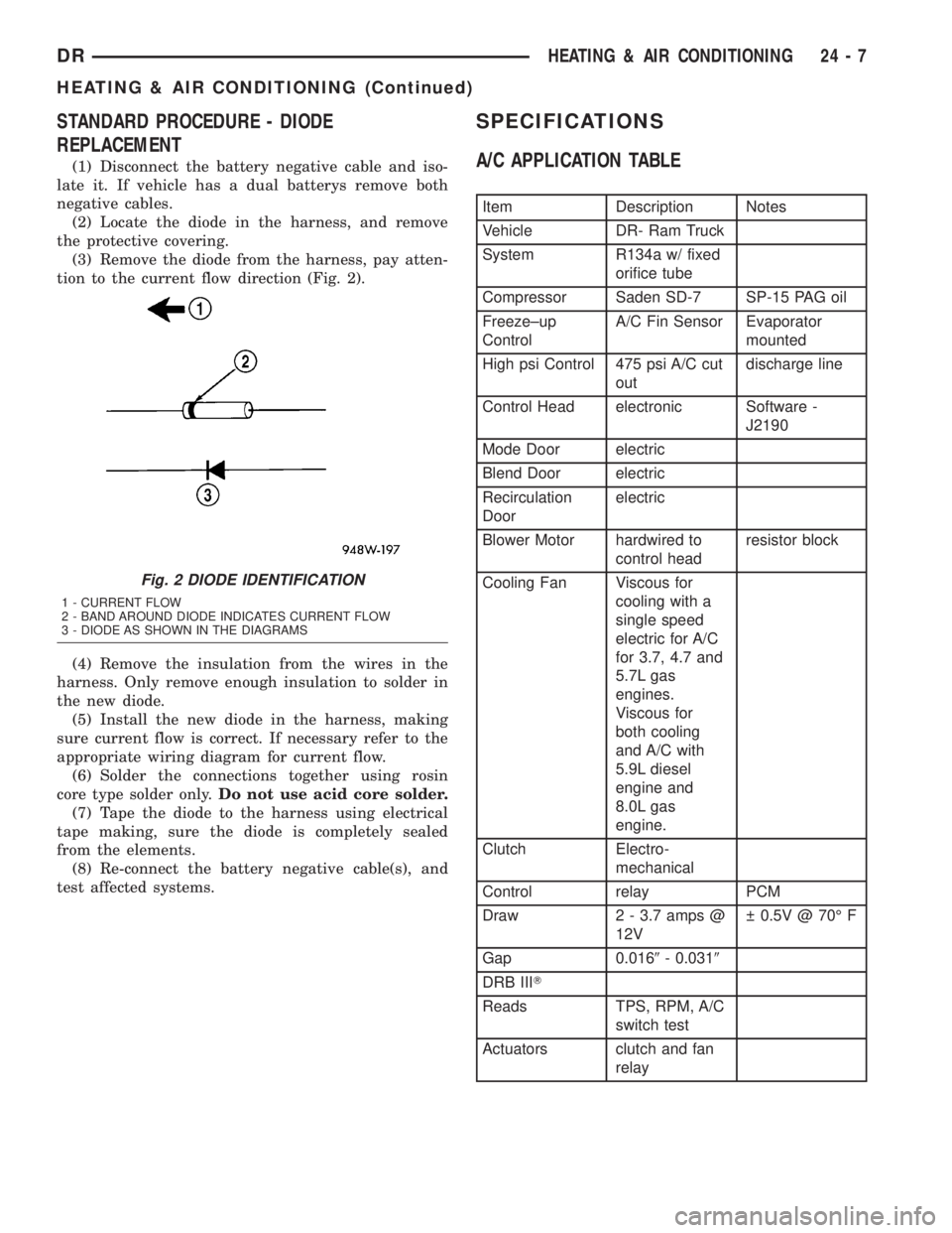
tion to the current flow direction (Fig. 2).
(4) Remove the insulation from the wires in the
harness. Only remove enough insulation to solder in
the new diode.
(5) Install the new diode in the harness, making
sure current flow is correct. If necessary refer to the
appropriate wiring diagram for current flow.
(6) Solder the connections together using rosin
core type solder only.Do not use acid core solder.
(7) Tape the diode to the harness using electrical
tape making, sure the diode is completely sealed
from the elements.
(8) Re-connect the battery negative cable(s), and
test affected systems.
SPECIFICATIONS
A/C APPLICATION TABLE
Item Description Notes
Vehicle DR- Ram Truck
System R134a w/ fixed
orifice tube
Compressor Saden SD-7 SP-15 PAG oil
Freeze±up
ControlA/C Fin Sensor Evaporator
mounted
High psi Control 475 psi A/C cut
outdischarge line
Control Head electronic Software -
J2190
Mode Door electric
Blend Door electric
Recirculation
Doorelectric
Blower Motor hardwired to
control headresistor block
Cooling Fan Viscous for
cooling with a
single speed
electric for A/C
for 3.7, 4.7 and
5.7L gas
engines.
Viscous for
both cooling
and A/C with
5.9L diesel
engine and
8.0L gas
engine.
Clutch Electro-
mechanical
Control relay PCM
Draw 2 - 3.7 amps @
12V 0.5V @ 70É F
Gap 0.0169- 0.0319
DRB IIIT
Reads TPS, RPM, A/C
switch test
Actuators clutch and fan
relay
Fig. 2 DIODE IDENTIFICATION
1 - CURRENT FLOW
2 - BAND AROUND DIODE INDICATES CURRENT FLOW
3 - DIODE AS SHOWN IN THE DIAGRAMS
DRHEATING & AIR CONDITIONING 24 - 7
HEATING & AIR CONDITIONING (Continued)
Page 2785 of 2895
seconds. Refer to Electronic Control Modules for
more information on the JTEC controls.
DIAGNOSIS AND TESTING - A/C COMPRESSOR
CLUTCH COIL
For circuit descriptions and diagrams, (Refer to
Appropriate Wiring Information). The battery must
be fully-charged before performing the following
tests. Refer to Battery for more information.
(1) Connect an ammeter (0 to 10 ampere scale) in
series with the clutch coil terminal. Use a voltmeter
(0 to 20 volt scale) with clip-type leads for measuring
the voltage across the battery and the compressor
clutch coil.
(2) With the A/C Heater mode control switch in
any A/C mode, and the blower motor switch in the
lowest speed position, start the engine and run it at
normal idle.
(3) The compressor clutch coil voltage should read
within 0.2 volts of the battery voltage. If there is
voltage at the clutch coil, but the reading is not
within 0.2 volts of the battery voltage, test the clutch
coil feed circuit for excessive voltage drop and repair
as required. If there is no voltage reading at the
clutch coil, use a DRB IIItscan tool and (Refer to
Appropriate Diagnostic Information) for testing of the
compressor clutch circuit and PCM control. The fol-
lowing components must be checked and repaired as
required before you can complete testing of the clutch
coil:
²Fuses in the junction block and the Power Dis-
tribution Center (PDC)
²A/C heater mode control switch
²Compressor clutch relay
²A/C high pressure transducer switch²JTEC
(4) The compressor clutch coil is acceptable if the
current draw measured at the clutch coil is 2.0 to 3.9
amperes with the electrical system voltage at 11.5 to
12.5 volts. This should only be checked with the work
area temperature at 21É C (70É F). If system voltage
is more than 12.5 volts, add electrical loads by turn-
ing on electrical accessories until the system voltage
drops below 12.5 volts.
(a) If the clutch coil current reading is four
amperes or more, the coil is shorted and should be
replaced.
(b) If the clutch coil current reading is zero, the
coil is open and should be replaced.
STANDARD PROCEDURE - A/C COMPRESSOR
CLUTCH BREAK-IN
After a new compressor clutch has been installed,
cycle the compressor clutch approximately twenty
times (five seconds on, then five seconds off). During
this procedure, set the A/C Heater control to the
Recirculation Mode, the blower motor switch in the
highest speed position, and the engine speed at 1500
to 2000 rpm. This procedure (burnishing) will seat
the opposing friction surfaces and provide a higher
compressor clutch torque capability.
REMOVAL
The refrigerant system can remain fully-charged
during compressor clutch, rotor, or coil replacement.
The compressor clutch can be serviced in the vehicle.
(1) Disconnect and isolate the battery negative
cable.
(2) Remove the serpentine drive belt(Refer to 7 -
COOLING/ACCESSORY DRIVE/DRIVE BELTS -
REMOVAL).
(3) Unplug the compressor clutch coil wire harness
connector.
(4) Remove the bolts that secure the compressor to
the mounting bracket.
(5) Remove the compressor from the mounting
bracket. Support the compressor in the engine com-
partment while servicing the clutch.
(6) Insert the two pins of the spanner wrench
(Special Tool C-4489 or equivalent) into the holes of
the clutch plate. Hold the clutch plate stationary and
remove the hex nut (Fig. 2).
(7) Remove the clutch plate.
(8) Remove the compressor clutch shims.
(9) Remove the external front housing snap ring
with snap ring pliers (Fig. 3).
(10)
Install the lip of the rotor puller (Special Tool
C-6141-1 or equivalent) into the snap ring groove
exposed in the previous step, and install the shaft pro-
tector (Special Tool C-6141-2 or equivalent) (Fig. 4).
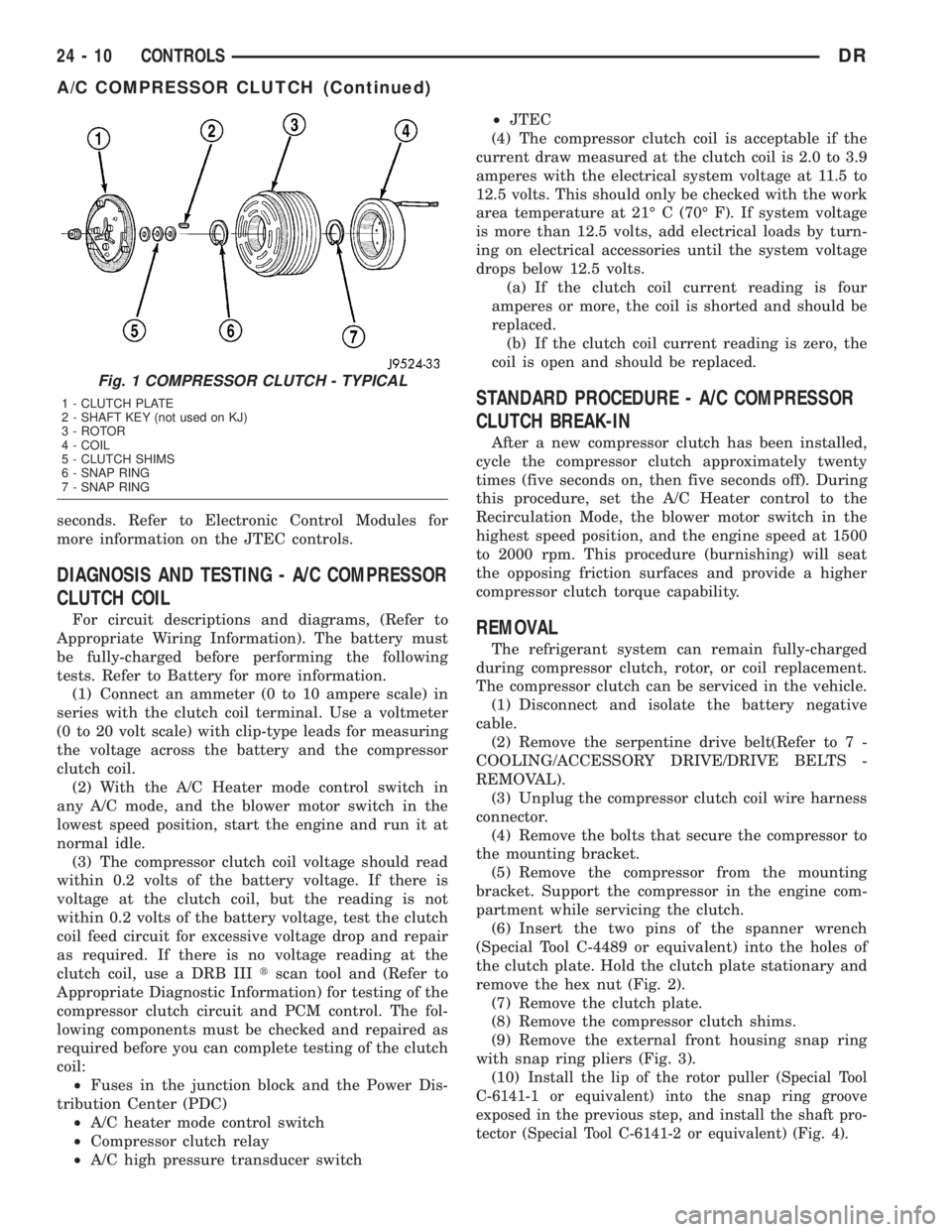
Fig. 1 COMPRESSOR CLUTCH - TYPICAL
1 - CLUTCH PLATE
2 - SHAFT KEY (not used on KJ)
3 - ROTOR
4 - COIL
5 - CLUTCH SHIMS
6 - SNAP RING
7 - SNAP RING
24 - 10 CONTROLSDR
A/C COMPRESSOR CLUTCH (Continued)
Page 2789 of 2895
for relay terminal 86 with the ignition switch in the
On position. If OK, go to Step 5. If not OK, repair the
open circuit to the fuse in the junction block as
required.
(5) The coil ground terminal cavity (85) is switched
to ground through the Powertrain Control Module
(PCM). There should be continuity between this cav-
ity and the A/C compressor clutch relay control cir-
cuit cavity of the PCM wire harness connector C
(gray) at all times. If not OK, repair the open circuit
as required.
REMOVAL
(1) Disconnect and isolate the battery negative
cable.
(2) Remove the cover from the Power Distribution
Center (PDC).
(3) Refer to the label on the PDC for compressor
clutch relay identification and location.
(4) Unplug the compressor clutch relay from the
PDC.
INSTALLATION
(1) Install the compressor clutch relay by aligning
the relay terminals with the cavities in the PDC and
pushing the relay firmly into place.
(2) Install the PDC cover.
(3) Connect the battery negative cable.
(4) Test the relay operation.
A/C HEATER CONTROL
DESCRIPTION
The A/C heater system uses a seriers of electrical
controls. These controls provide the vehicle operator
with a number of setting options to help control the
climate and comfort within the vehicle. Refer to the
owner's manual in the vehicle glove box for more
information on the features, use, and suggested oper-
ation of these controls.
The A/C heater control - (Single Zone) or (Dual
Zone) panel is located to the right of the instrument
cluster on the instrument panel.
The control panel contains a rotary-type tempera-
ture control, a rotary-type mode control switch knob,
and a rotary-type blower motor speed switch knob.
The control also has a push button to activate the
Optional side view mirrors defroster elements and to
turn the A/C on.
The Dual Zone HVAC control panel contains a pair
of slider-type temperature controls, a rotary-type
mode control switch knob and a rotary-type blower
motor speed switch knob. The control also has but-
tons to turn the A/C ON, Set it on Max A/C and for
the Optional Heated Sideview Mirrors.The A/C heater control panel cannot be repaired. If
faulty or damaged, the entire unit must be replaced.
The illumination lamps are available for service
replacement.
REMOVAL
WARNING: ON VEHICLES EQUIPPED WITH AIR-
BAGS, DISABLE THE AIRBAG SYSTEM BEFORE
ATTEMPTING ANY STEERING WHEEL, STEERING
COLUMN, OR INSTRUMENT PANEL COMPONENT
DIAGNOSIS OR SERVICE. DISCONNECT AND ISO-
LATE THE BATTERY NEGATIVE (GROUND) CABLE,
THEN WAIT TWO MINUTES FOR THE AIRBAG SYS-
TEM CAPACITOR TO DISCHARGE BEFORE PER-
FORMING FURTHER DIAGNOSIS OR SERVICE. THIS
IS THE ONLY SURE WAY TO DISABLE THE AIRBAG
SYSTEM. FAILURE TO TAKE THE PROPER PRE-
CAUTIONS COULD RESULT IN AN ACCIDENTAL
AIRBAG DEPLOYMENT AND POSSIBLE PERSONAL
INJURY.
(1) Disconnect and isolate the battery negative
cable.
(2) Remove the center bezel from the instrument
panel(Refer to 23 - BODY/INSTRUMENT PANEL/IN-
STRUMENT PANEL CENTER BEZEL - REMOVAL).
(3) Remove the screws that secure the A/C Heater
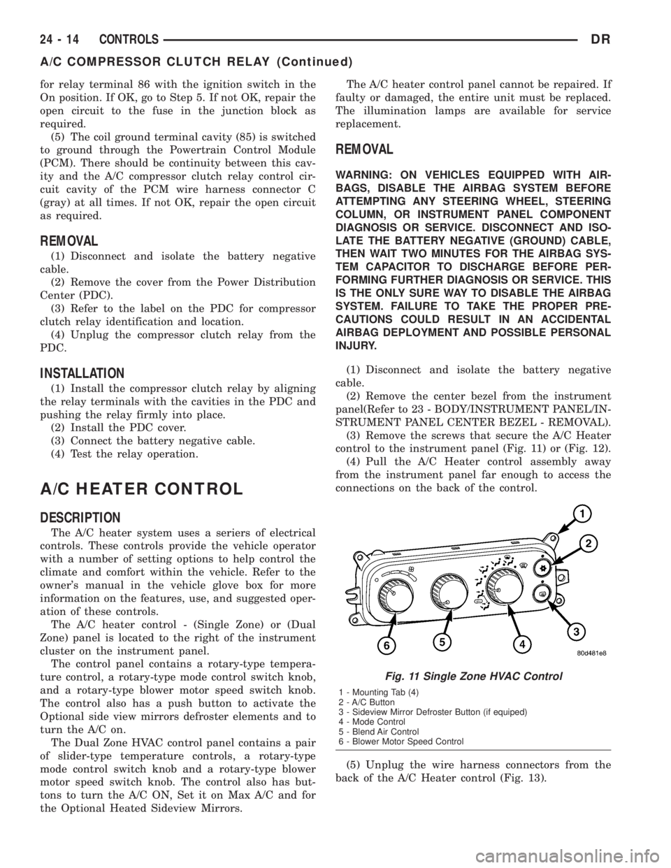
control to the instrument panel (Fig. 11) or (Fig. 12).
(4) Pull the A/C Heater control assembly away
from the instrument panel far enough to access the
connections on the back of the control.
(5) Unplug the wire harness connectors from the
back of the A/C Heater control (Fig. 13).
Fig. 11 Single Zone HVAC Control
1 - Mounting Tab (4)
2 - A/C Button
3 - Sideview Mirror Defroster Button (if equiped)
4 - Mode Control
5 - Blend Air Control
6 - Blower Motor Speed Control
24 - 14 CONTROLSDR
A/C COMPRESSOR CLUTCH RELAY (Continued)
Page 2813 of 2895
INSTALLATION
INSTALLATION
WARNING: REVIEW THE WARNINGS AND CAU-
TIONS IN THE FRONT OF THIS SECTION BEFORE
PERFORMING THE FOLLOWING OPERATION.
(Refer to 24 - HEATING & AIR CONDITIONING/
PLUMBING - WARNING) (Refer to 24 - HEATING &
AIR CONDITIONING/PLUMBING - CAUTION) (Refer
to 24 - HEATING & AIR CONDITIONING/PLUMBING -
CAUTION - REFRIGERANT HOSES/LINES/TUBES
PRECAUTIONS)
The compressor may be removed and repositioned
without disconnecting the refrigerant lines or dis-
charging the refrigerant system. Discharging is not
necessary if servicing the compressor clutch or clutch
coil, the engine, the cylinder head, or the generator.
NOTE: If a replacement compressor is being
installed, be certain to check the refrigerant oil
level. (Refer to 24 - HEATING & AIR CONDITIONING/
PLUMBING/REFRIGERANT OIL - STANDARD PRO-
CEDURE - REFRIGERANT OIL LEVEL) Use only
refrigerant oil of the type recommended for the
compressor in the vehicle. (Refer to 24 - HEATING &AIR CONDITIONING/PLUMBING/REFRIGERANT OIL -
DESCRIPTION)
(1) Install the compressor to the mounting bracket.
(2) On the 3.7L, 4.7L, 5.7L and 8.0L gasoline
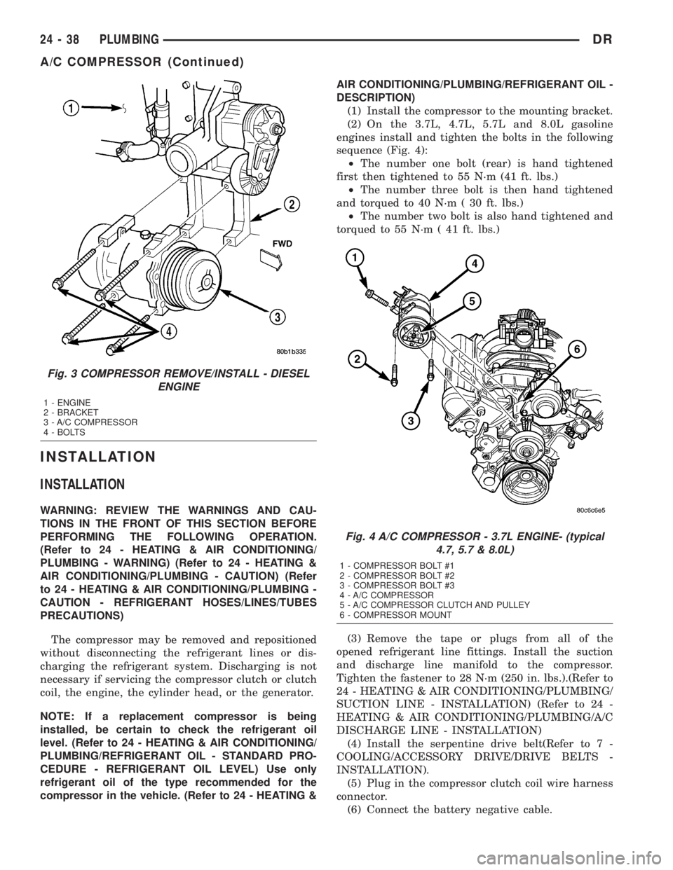
engines install and tighten the bolts in the following
sequence (Fig. 4):
²The number one bolt (rear) is hand tightened
first then tightened to 55 N´m (41 ft. lbs.)
²The number three bolt is then hand tightened
and torqued to 40 N´m ( 30 ft. lbs.)
²The number two bolt is also hand tightened and
torqued to 55 N´m ( 41 ft. lbs.)
(3) Remove the tape or plugs from all of the
opened refrigerant line fittings. Install the suction
and discharge line manifold to the compressor.
Tighten the fastener to 28 N´m (250 in. lbs.).(Refer to
24 - HEATING & AIR CONDITIONING/PLUMBING/
SUCTION LINE - INSTALLATION) (Refer to 24 -
HEATING & AIR CONDITIONING/PLUMBING/A/C
DISCHARGE LINE - INSTALLATION)
(4) Install the serpentine drive belt(Refer to 7 -
COOLING/ACCESSORY DRIVE/DRIVE BELTS -
INSTALLATION).
(5) Plug in the compressor clutch coil wire harness
connector.
(6) Connect the battery negative cable.
Fig. 3 COMPRESSOR REMOVE/INSTALL - DIESEL
ENGINE
1 - ENGINE
2 - BRACKET
3 - A/C COMPRESSOR
4 - BOLTS
Fig. 4 A/C COMPRESSOR - 3.7L ENGINE- (typical
4.7, 5.7 & 8.0L)
1 - COMPRESSOR BOLT #1
2 - COMPRESSOR BOLT #2
3 - COMPRESSOR BOLT #3
4 - A/C COMPRESSOR
5 - A/C COMPRESSOR CLUTCH AND PULLEY
6 - COMPRESSOR MOUNT
24 - 38 PLUMBINGDR
A/C COMPRESSOR (Continued)