2003 DODGE RAM battery replacement
[x] Cancel search: battery replacementPage 509 of 2895
WARNING: ON VEHICLES EQUIPPED WITH AIR-
BAGS, DISABLE THE SUPPLEMENTAL RESTRAINT
SYSTEM BEFORE ATTEMPTING ANY STEERING
WHEEL, STEERING COLUMN, DRIVER AIRBAG,
PASSENGER AIRBAG, SEAT BELT TENSIONER,
SIDE CURTAIN AIRBAG, OR INSTRUMENT PANEL
COMPONENT DIAGNOSIS OR SERVICE. DISCON-
NECT AND ISOLATE THE BATTERY NEGATIVE
(GROUND) CABLE, THEN WAIT TWO MINUTES FOR
THE SYSTEM CAPACITOR TO DISCHARGE BEFORE
PERFORMING FURTHER DIAGNOSIS OR SERVICE.
THIS IS THE ONLY SURE WAY TO DISABLE THE
SUPPLEMENTAL RESTRAINT SYSTEM. FAILURE TO
TAKE THE PROPER PRECAUTIONS COULD
RESULT IN ACCIDENTAL AIRBAG DEPLOYMENT
AND POSSIBLE PERSONAL INJURY.
CLUSTER BULB
This procedure applies to each of the incandescent
cluster illumination lamp bulb and bulb holder units.
If the vehicle is equipped with the optional Remote
Keyless Entry (RKE) system, and the RKE receiver
module was removed from the instrument cluster
rear cover to access the lower center cluster illumi-
nation lamp, reinstall the RKE module after the bulb
is replaced on the circuit board. (Refer to 8 - ELEC-
TRICAL/POWER LOCKS/REMOTE KEYLESS
ENTRY MODULE - INSTALLATION).
CAUTION: Always use the correct bulb size and
type for replacement. An incorrect bulb size or type
may overheat and cause damage to the instrument
cluster, the electronic circuit board and/or the
gauges.
(1) Insert the bulb and bulb holder unit straight
into the correct bulb mounting hole in the cluster
electronic circuit board (Fig. 6).
(2) With the bulb holder fully seated against the
cluster electronic circuit board, turn the bulb holder
clockwise about sixty degrees to lock it into place.
(3) Reinstall the instrument cluster onto the
instrument panel. (Refer to 8 - ELECTRICAL/IN-
STRUMENT CLUSTER - INSTALLATION).
(4) Reconnect the battery negative cable.CLUSTER LENS, HOOD, AND MASK
(1) Position the cluster lens, hood, and mask unit
over the face of the instrument cluster (Fig. 7). Be
certain that the odometer/trip odometer switch but-
ton is inserted through the proper clearance holes in
the mask and the lens.
(2) From the back of the instrument cluster, install
and tighten the eight screws around the outer perim-
eter of the rear cover that secure the lens, hood, and
mask unit to the cluster housing. Tighten the screws
to 1 N´m (10 in. lbs.).
(3) Reinstall the instrument cluster onto the
instrument panel. (Refer to 8 - ELECTRICAL/IN-
STRUMENT CLUSTER - INSTALLATION).
(4) Reconnect the battery negative cable.
INSTALLATION
WARNING: ON VEHICLES EQUIPPED WITH AIR-
BAGS, DISABLE THE SUPPLEMENTAL RESTRAINT
SYSTEM BEFORE ATTEMPTING ANY STEERING
WHEEL, STEERING COLUMN, DRIVER AIRBAG,
PASSENGER AIRBAG, SEAT BELT TENSIONER,
SIDE CURTAIN AIRBAG, OR INSTRUMENT PANEL
COMPONENT DIAGNOSIS OR SERVICE. DISCON-
NECT AND ISOLATE THE BATTERY NEGATIVE
(GROUND) CABLE, THEN WAIT TWO MINUTES FOR
THE SYSTEM CAPACITOR TO DISCHARGE BEFORE
PERFORMING FURTHER DIAGNOSIS OR SERVICE.
THIS IS THE ONLY SURE WAY TO DISABLE THE
SUPPLEMENTAL RESTRAINT SYSTEM. FAILURE TO
TAKE THE PROPER PRECAUTIONS COULD
RESULT IN ACCIDENTAL AIRBAG DEPLOYMENT
AND POSSIBLE PERSONAL INJURY.
(1) Position the instrument cluster to the instru-
ment panel.
(2) Reconnect the instrument panel wire harness
connectors for the cluster to the connector receptacles
on the back of the cluster housing.
(3) Position the instrument cluster into the instru-
ment panel.
(4) Install and tighten the four screws that secure
the instrument cluster to the instrument panel struc-
tural support (Fig. 5). Tighten the screws to 4 N´m
(31 in. lbs.).
(5) Reinstall the cluster bezel onto the instrument
panel. (Refer to 23 - BODY/INSTRUMENT PANEL/
CLUSTER BEZEL - INSTALLATION).
(6) Reconnect the battery negative cable.
8J - 16 INSTRUMENT CLUSTERDR
INSTRUMENT CLUSTER (Continued)
Page 559 of 2895
TRAILER TOW WIRING
DESCRIPTION
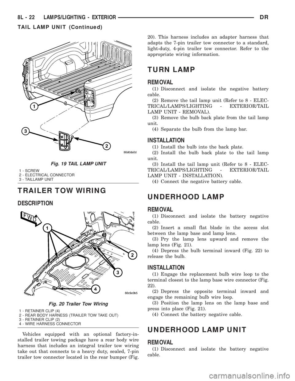
Vehicles equipped with an optional factory-in-
stalled trailer towing package have a rear body wire
harness that includes an integral trailer tow wiring
take out that connects to a heavy duty, sealed, 7-pin
trailer tow connector located in the rear bumper (Fig.20). This harness includes an adapter harness that
adapts the 7-pin trailer tow connector to a standard,
light-duty, 4-pin trailer tow connector. Refer to the
appropriate wiring information.
TURN LAMP
REMOVAL
(1) Disconnect and isolate the negative battery
cable.
(2) Remove the tail lamp unit (Refer to 8 - ELEC-
TRICAL/LAMPS/LIGHTING - EXTERIOR/TAIL
LAMP UNIT - REMOVAL).
(3) Remove the bulb back plate from the tail lamp
unit.
(4) Separate the bulb from the lamp bar.
INSTALLATION
(1) Install the bulb into the back plate.
(2) Install the bulb back plate to the tail lamp
unit.
(3) Install the tail lamp unit (Refer to 8 - ELEC-
TRICAL/LAMPS/LIGHTING - EXTERIOR/TAIL
LAMP UNIT - INSTALLATION).
(4) Connect the negative battery cable.
UNDERHOOD LAMP
REMOVAL
(1) Disconnect and isolate the battery negative
cable.
(2) Insert a small flat blade in the access slot
between the lamp base and lamp lens.
(3) Pry the lamp lens upward and remove the
lamp lens (Fig. 21).
(4) Depress the bulb terminal inward (Fig. 22) to
release the bulb.
INSTALLATION
(1) Engage the replacement bulb wire loop to the
terminal closest to the lamp base wire connector (Fig.
22).
(2) Depress the opposite terminal inward and
engage the remaining bulb wire loop.
(3) Position the lamp lens on the lamp base and
press into place (Fig. 21).
(4) Connect the battery negative cable.
UNDERHOOD LAMP UNIT
REMOVAL
(1) Disconnect and isolate the battery negative
cable.
Fig. 19 TAIL LAMP UNIT
1 - SCREW
2 - ELECTRICAL CONNECTOR
3 - TAILLAMP UNIT
Fig. 20 Trailer Tow Wiring
1 - RETAINER CLIP (4)
2 - REAR BODY HARNESS (TRAILER TOW TAKE OUT)
3 - RETAINER CLIP (2)
4 - WIRE HARNESS CONNECTOR
8L - 22 LAMPS/LIGHTING - EXTERIORDR
TAIL LAMP UNIT (Continued)
Page 563 of 2895

(4) Push the glove box lamp and switch unit into
the hole in the mounting bracket on the instrument
panel glove box opening upper reinforcement.
(5) Install the glove box onto the instrument panel.
(Refer to 23 - BODY/INSTRUMENT PANEL/GLOVE
BOX - INSTALLATION) for the procedures.
(6) Close the glove box.
(7) Reconnect the battery negative cable.
READING LAMP
DESCRIPTION
The overhead console in this vehicle is equipped
with two individual reading and courtesy lamps. The
lamp lenses are the only visible components of these
lamps. Each lamp has its own switch, bulb, reflector
and lens within the overhead console.
The overhead console reading and courtesy lamps
are controlled by the instrument cluster which pro-
vides power at all times, regardless of the ignition
switch position. The ground circuit for the lamps is
switched through the integral reading and courtesy
lamp switches or through the door ajar switches.
Each lamp is designed and aimed to provide illumi-
nation that will be directed only to that side of the
vehicle on which the lamp is located.
The reading and courtesy lamp lenses and bulbs
are available for service replacement. The reading
and courtesy lamp switches, bulb holders and wiring
are only available as part of the overhead console
wire harness. If either of the lamp switches or bulb
holders is faulty or damaged, the entire overhead
console wire harness assembly must be replaced.
For service of the reading and courtesy lamp bulbs,
refer to the appropriate wiring information.
OPERATION
All reading and courtesy lamps located in the over-
head console are activated by the door ajar switches
via the instrument cluster. When all of the doors are
closed, these lamps can be individually activated by
depressing the corresponding lens. When any door is
open, depressing the lamp lenses to activate the lamp
switches will not turn the lamps off.
The instrument cluster monitors the door ajar
switches. When a door is open the instrument cluster
grounds the low side drivers to turn on the lamps.
Upon closing all doors, the instrument cluster ini-
tiates a 30 second timer. If any of the doors are
opened during the ªtime outº cycle, the instrument
cluster will reset the timer until all doors are closed.
The instrument cluster will faid to off when the doors
are closed and the ignition is turned ON, the time
out expires or the power locks are activated.
REMOVAL
(1) Disconnect and isolate the battery negative
cable.
(2) Insert a long, narrow, flat-bladed tool between
the curved (outboard) edge of the reading and cour-
tesy lamp lens and the overhead console housing
(Fig. 4).
(3) Gently pry inward and downward against the
lens until the latch tab in the center of the outboard
edge of the reading and courtesy lamp lens is disen-
gaged from the overhead console housing.
(4)
Pull firmly on the lens toward the outboard side
of the vehicle to disengage the two pivot tabs on the
inboard edge of the reading and courtesy lamp lens
are disengaged from the overhead console housing.
(5) Remove the reading and courtesy lamp lens
from the overhead console housing.
INSTALLATION
(1) Position the reading and courtesy lamp lens
onto the overhead console housing.
(2) Align the two pivot tabs on the inboard edge of
the reading and courtesy lamp lens with the two
pivot holes in the overhead console housing.
(3) Push firmly on the lens toward the inboard
side of the vehicle to insert the two pivot tabs on the
inboard edge of the reading and courtesy lamp lens
into the two pivot holes in the overhead console hous-
ing.
(4) Pivot the lens back up into position and press
upward firmly until the latch tab in the center of the
outboard edge of the reading and courtesy lamp lens
snaps back into the overhead console housing.
(5) Reconnect the battery negative cable.
Fig. 4 Overhead Console Reading Lamp Bulb
Removal
1 - LENS
2 - FLAT BLADE
3 - CONSOLE
8L - 26 LAMPS/LIGHTING - INTERIORDR
GLOVE BOX LAMP/SWITCH (Continued)
Page 566 of 2895
(1) With the ignition switch in the Off position,
simultaneously depress and hold theSTEP and
RESET buttons.
(2) Turn the ignition switch to the On position.
(3) Following completion of the test, the electronics
module will display one of the following messages:
a.Pass Self Test (EVIC only), PASS (CMTC)-
The electronics module is working properly.
b.Failed Self Test (EVIC only), FAIL (CMTC)-
The electronics module has an internal failure. The
electronics module is faulty and must be replaced.
c.Failed J1850 Communication (EVIC only),
BUS (CMTC)- The electronics module is not receiv-
ing proper message input through the J1850 PCI
data bus circuit. This can result from one or more
faulty electronic modules in the vehicle, or from a
faulty PCI data bus. The use of a DRB IIItscan tool
and the proper Diagnostic Procedures manual are
required for further diagnosis.
NOTE: If the compass functions, but accuracy is
suspect, it may be necessary to perform a variation
adjustment. This procedure allows the compass
unit to accommodate variations in the earth's mag-
netic field strength, based on geographic location.
Refer to Compass Variation Adjustment in the Stan-
dard Procedures section of this group.
NOTE: If the compass reading displays dashes, and
only ªCALº appears in the display, demagnetizing
may be necessary to remove excessive residual
magnetic fields from the vehicle. Refer to Compass
Demagnetizing in the Standard Procedures section
of this group.
STANDARD PROCEDURE
STANDARD PROCEDURE - READING/
COURTESY LAMP REPLACEMENT
(1) Open hood, disconnect and isolate the negative
battery cable.
(2) Remove the reading/courtesy lamp lens. Using
a trim stick, gently pry the forward edge of the read-
ing/courtesy lamp lens outward.
(3) Remove the reading/courtesy lamp socket from
the overhead console. Rotate the reading/courtesy
lamp socket one quarter turn counter clockwise.
(4) Remove the lamp and socket assembly.
(5) Reverse the above procedure to install.
STANDARD PROCEDURE - MODULE LENS
REPLACEMENT
(1) Remove the overhead console (Refer to 8 -
ELECTRICAL/OVERHEAD CONSOLE - REMOV-
AL).
(2) Remove the electronics module from the over-
head console. Refer to the procedure later in this sec-
tion.
(3) Unsnap the lens from the module and replace
lens as necessary.
STANDARD PROCEDURE - MODULE LAMP
REPLACEMENT
(1) Remove the overhead console (Refer to 8 -
ELECTRICAL/OVERHEAD CONSOLE - REMOV-
AL).
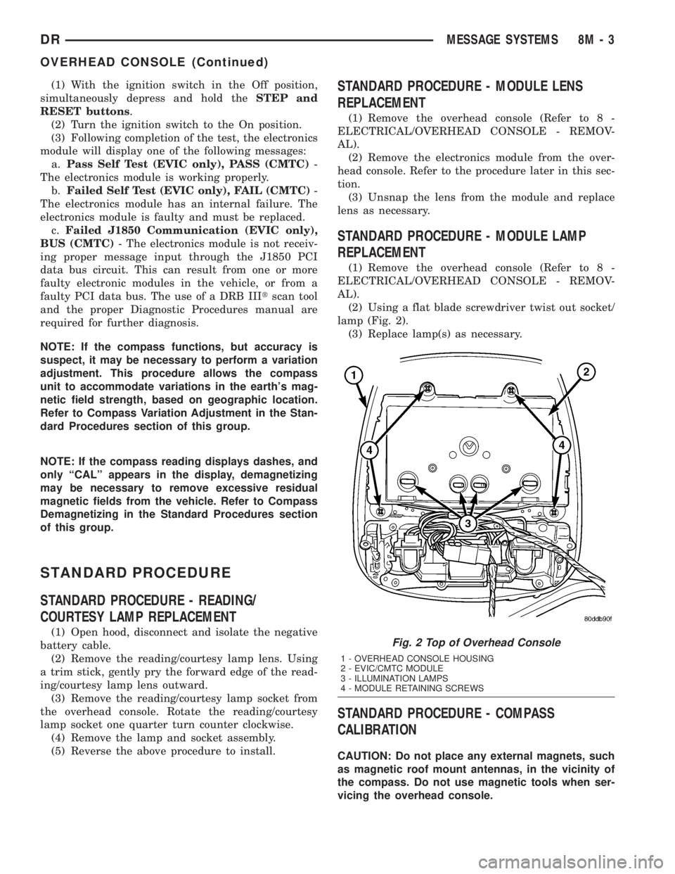
(2) Using a flat blade screwdriver twist out socket/
lamp (Fig. 2).
(3) Replace lamp(s) as necessary.
STANDARD PROCEDURE - COMPASS
CALIBRATION
CAUTION: Do not place any external magnets, such
as magnetic roof mount antennas, in the vicinity of
the compass. Do not use magnetic tools when ser-
vicing the overhead console.
Fig. 2 Top of Overhead Console
1 - OVERHEAD CONSOLE HOUSING
2 - EVIC/CMTC MODULE
3 - ILLUMINATION LAMPS
4 - MODULE RETAINING SCREWS
DRMESSAGE SYSTEMS 8M - 3
OVERHEAD CONSOLE (Continued)
Page 596 of 2895
the power seat track fails to operate in more than
one direction, proceed as follows:
(1) Check the power seat fuse in the power distri-
bution center. If OK, go to Step 2. If not OK, replace
the faulty fuse.
(2) Remove the power seat switch from the seat.
Check for battery voltage at the fused B(+) circuit
cavity of the power seat switch wire harness connec-
tor. If OK, go to Step 3. If not OK, repair the open
circuit to the power distribution center as required.
(3) Check for continuity between the ground cir-
cuit cavity of the power seat switch wire harness con-
nector and a good ground. There should be
continuity. If OK, go to Step 4. If not OK, repair the
open circuit to ground as required.
(4) Test the power seat switch as described in this
group. If the switch tests OK, check the wire harness
between the power seat switch and the motor for
shorts or opens. If the circuits check OK, replace the
faulty power seat track (adjuster) assembly. If the
circuits are not OK, repair the wire harness as
required.
REMOVAL
(1) Remove the appropriate seat from the vehicle.
(Refer to 23 - BODY/SEATS/SEAT - REMOVAL).
(2) Remove the power seat switch from the seat.
Refer to the procedure in this section of the service
manual.
(3) Remove four seat track mounting nuts from
cushion pan.
(4) Disconnect the power seat electrical and
remove the seat track from the seat cushion.
(5) Remove the necessary components that must
be transferred to the replacement seat track (seat
belt buckles, wire harness, etc.).
INSTALLATION
(1) Install the necessary components that must be
transferred to the replacement seat track (seat belt
buckles, wire harness, etc.).
(2) Position the seat track and install the retaining
nuts on the seat cushion pan studs. Torque the bolts
to 25 N´m.
(3) Route and connect the power seat electrical on
the seat track and cushion pan.
(4) Install the power seat switch on the seat. Refer
to the procedure in this section of the service man-
ual.
(5) Install the seat in the vehicle (Refer to 23 -
BODY/SEATS/SEAT - INSTALLATION).
(6) Connect the negative battery cable.
LUMBAR CONTROL SWITCH
DESCRIPTION
The power lumbar seat option includes an electri-
cally operated lumbar support mechanism. A single
two-way momentary power lumbar switch is integral
with the power seat switches. The power lumbar
switch is secured to the back of the seat cushion side
shield with screws, and the switch paddle protrudes
through a hole to the outside of the shield. The
switch paddle is located in a shallow depression
molded into the outer surface of the seat cushion side
shield that helps to shroud it from unintentional
actuation when entering or leaving the vehicle.
The power lumbar switches cannot be adjusted or
repaired and, if faulty or damaged, the seat switch
assembly must be replaced.
OPERATION
When the power lumbar switch paddle is actuated,
a battery feed and a ground path are applied through
the switch contacts to the power lumbar adjuster
motor. The motor operates to move the lumbar
adjuster through its drive unit in the selected direc-
tion until the switch is released, or until the travel
limit of the adjuster is reached. When the switch is
moved in the opposite direction, the battery feed and
ground path to the motor are reversed through the
switch contacts. This causes the motor to run in the
opposite direction.
The power lumbar switch should not be held
applied in either direction after the adjuster has
reached its travel limit. The power lumbar adjuster
motor contains a self-resetting circuit breaker to pro-
tect it from overload. However, consecutive or fre-
quent resetting of the circuit breaker must not be
allowed to continue, or the motor may be damaged.
REMOVAL
The power lumbar switch is integral with the other
power seat switches. Refer to the appropriate driver
or passenger power front seat switch removal and/or
installation procedure.
LUMBAR MOTOR
DESCRIPTION
The power lumbar seat option includes an electri-
cally operated lumbar support mechanism. The only
visible evidence of this option is the separate power
lumbar switch control paddle that is located on the
outboard seat cushion side shield, next to the other
power seat switch control knobs. The power lumbar
adjuster and motor are concealed beneath the seat
back trim cover and padding, where they are secured
DRPOWER SEATS 8N - 19
POWER SEAT TRACK (Continued)
Page 609 of 2895
way inside, so that you avoid kneeling or sitting on a
non-cleaned area.
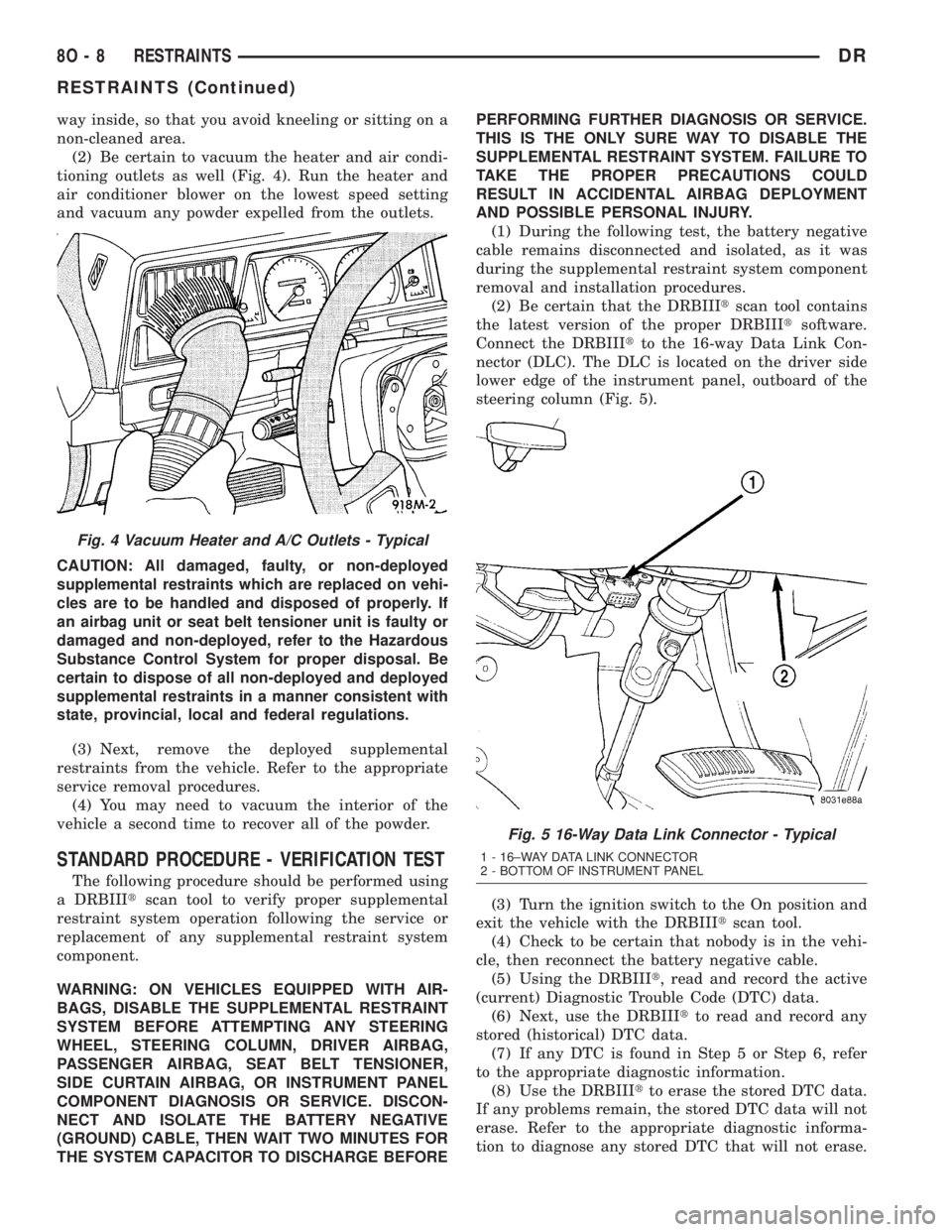
(2) Be certain to vacuum the heater and air condi-
tioning outlets as well (Fig. 4). Run the heater and
air conditioner blower on the lowest speed setting
and vacuum any powder expelled from the outlets.
CAUTION: All damaged, faulty, or non-deployed
supplemental restraints which are replaced on vehi-
cles are to be handled and disposed of properly. If
an airbag unit or seat belt tensioner unit is faulty or
damaged and non-deployed, refer to the Hazardous
Substance Control System for proper disposal. Be
certain to dispose of all non-deployed and deployed
supplemental restraints in a manner consistent with
state, provincial, local and federal regulations.
(3) Next, remove the deployed supplemental
restraints from the vehicle. Refer to the appropriate
service removal procedures.
(4) You may need to vacuum the interior of the
vehicle a second time to recover all of the powder.
STANDARD PROCEDURE - VERIFICATION TEST
The following procedure should be performed using
a DRBIIItscan tool to verify proper supplemental
restraint system operation following the service or
replacement of any supplemental restraint system
component.
WARNING: ON VEHICLES EQUIPPED WITH AIR-
BAGS, DISABLE THE SUPPLEMENTAL RESTRAINT
SYSTEM BEFORE ATTEMPTING ANY STEERING
WHEEL, STEERING COLUMN, DRIVER AIRBAG,
PASSENGER AIRBAG, SEAT BELT TENSIONER,
SIDE CURTAIN AIRBAG, OR INSTRUMENT PANEL
COMPONENT DIAGNOSIS OR SERVICE. DISCON-
NECT AND ISOLATE THE BATTERY NEGATIVE
(GROUND) CABLE, THEN WAIT TWO MINUTES FOR
THE SYSTEM CAPACITOR TO DISCHARGE BEFOREPERFORMING FURTHER DIAGNOSIS OR SERVICE.
THIS IS THE ONLY SURE WAY TO DISABLE THE
SUPPLEMENTAL RESTRAINT SYSTEM. FAILURE TO
TAKE THE PROPER PRECAUTIONS COULD
RESULT IN ACCIDENTAL AIRBAG DEPLOYMENT
AND POSSIBLE PERSONAL INJURY.
(1) During the following test, the battery negative
cable remains disconnected and isolated, as it was
during the supplemental restraint system component
removal and installation procedures.
(2) Be certain that the DRBIIItscan tool contains
the latest version of the proper DRBIIItsoftware.
Connect the DRBIIItto the 16-way Data Link Con-
nector (DLC). The DLC is located on the driver side
lower edge of the instrument panel, outboard of the
steering column (Fig. 5).
(3) Turn the ignition switch to the On position and
exit the vehicle with the DRBIIItscan tool.
(4) Check to be certain that nobody is in the vehi-
cle, then reconnect the battery negative cable.
(5) Using the DRBIIIt, read and record the active
(current) Diagnostic Trouble Code (DTC) data.
(6) Next, use the DRBIIItto read and record any
stored (historical) DTC data.
(7) If any DTC is found in Step 5 or Step 6, refer
to the appropriate diagnostic information.
(8) Use the DRBIIItto erase the stored DTC data.
If any problems remain, the stored DTC data will not
erase. Refer to the appropriate diagnostic informa-
tion to diagnose any stored DTC that will not erase.
Fig. 4 Vacuum Heater and A/C Outlets - Typical
Fig. 5 16-Way Data Link Connector - Typical
1 - 16±WAY DATA LINK CONNECTOR
2 - BOTTOM OF INSTRUMENT PANEL
8O - 8 RESTRAINTSDR
RESTRAINTS (Continued)
Page 620 of 2895

ber boot is installed over the engagement dowel to
eliminate contact noise between the dowel and the
steering wheel. The two lobes on the turn signal can-
cel cam on the lower surface of the clockspring rotor
hub contact a turn signal cancel actuator of the
multi-function switch to provide automatic turn sig-
nal cancellation. The yellow sleeved pigtail wires on
the upper surface of the clockspring rotor connect the
clockspring to the driver airbag, while a steering
wheel wire harness connects the two connector recep-
tacles on the upper surface of the clockspring rotor to
the horn switch feed pigtail wire connector and, if
the vehicle is so equipped, to the optional speed con-
trol and remote radio switches on the steering wheel.
Like the clockspring in a timepiece, the clockspring
tape has travel limits and can be damaged by being
wound too tightly during full stop-to-stop steering
wheel rotation. To prevent this from occurring, the
clockspring is centered when it is installed on the
steering column. Centering the clockspring indexes
the clockspring tape to the movable steering compo-
nents so that the tape can operate within its
designed travel limits. However, if the clockspring is
removed from the steering column or if the steering
shaft is disconnected from the steering gear, the
clockspring spool can change position relative to the
movable steering components. The clockspring must
be re-centered following completion of this service or
the tape may be damaged.
Service replacement clocksprings are shipped pre-
centered and with a plastic locking pin installed.
This locking pin should not be disengaged until the
clockspring has been installed on the steering col-
umn. If the locking pin is removed or damaged before
the clockspring is installed on a steering column, the
clockspring centering procedure must be performed.
(Refer to 8 - ELECTRICAL/RESTRAINTS/CLOCK-
SPRING - STANDARD PROCEDURE - CLOCK-
SPRING CENTERING).
STANDARD PROCEDURE - CLOCKSPRING
CENTERING
The clockspring is designed to wind and unwind
when the steering wheel is rotated, but is only
designed to rotate the same number of turns (about
five complete rotations) as the steering wheel can be
turned from stop to stop. Centering the clockspring
indexes the clockspring tape to other steering compo-
nents so that it can operate within its designed
travel limits. The rotor of a centered clockspring can
be rotated two and one-half turns in either direction
from the centered position, without damaging the
clockspring tape.
However, if the clockspring is removed for service
or if the steering column is disconnected from the
steering gear, the clockspring tape can change posi-tion relative to the other steering components. The
clockspring must then be re-centered following com-
pletion of such service or the clockspring tape may be
damaged. Service replacement clocksprings are
shipped pre-centered, with a plastic locking pin
installed (Fig. 19). This locking pin should not be
removed until the clockspring has been installed on
the steering column. If the locking pin is removed
before the clockspring is installed on a steering col-
umn, the clockspring centering procedure must be
performed.
WARNING: ON VEHICLES EQUIPPED WITH AIR-
BAGS, DISABLE THE SUPPLEMENTAL RESTRAINT
SYSTEM BEFORE ATTEMPTING ANY STEERING
WHEEL, STEERING COLUMN, DRIVER AIRBAG,
PASSENGER AIRBAG, SEAT BELT TENSIONER,
SIDE CURTAIN AIRBAG, OR INSTRUMENT PANEL
COMPONENT DIAGNOSIS OR SERVICE. DISCON-
NECT AND ISOLATE THE BATTERY NEGATIVE
(GROUND) CABLE, THEN WAIT TWO MINUTES FOR
THE SYSTEM CAPACITOR TO DISCHARGE BEFORE
PERFORMING FURTHER DIAGNOSIS OR SERVICE.
THIS IS THE ONLY SURE WAY TO DISABLE THE
SUPPLEMENTAL RESTRAINT SYSTEM. FAILURE TO
TAKE THE PROPER PRECAUTIONS COULD
RESULT IN ACCIDENTAL AIRBAG DEPLOYMENT
AND POSSIBLE PERSONAL INJURY.
Fig. 19 Clockspring and Multi-Function Switch
1 - CLOCKSPRING
2 - LOCATING PIN
3 - SCREW (2)
4 - LOCKING PIN
5 - ENGAGEMENT DOWEL BOOT
DRRESTRAINTS 8O - 19
CLOCKSPRING (Continued)
Page 622 of 2895
INSTALLATION
The clockspring cannot be repaired. It must be
replaced if faulty or damaged, or if the driver airbag
has been deployed.
If the clockspring is not properly centered in rela-
tion to the steering wheel, steering shaft and steer-
ing gear, it may be damaged. (Refer to 8 -
ELECTRICAL/RESTRAINTS/CLOCKSPRING -
STANDARD PROCEDURE - CLOCKSPRING CEN-
TERING). Service replacement clocksprings are
shipped pre-centered, with a plastic locking pin
installed. This locking pin should not be removed
until the clockspring has been installed on the steer-
ing column. If the locking pin is removed before the
clockspring is installed on a steering column, the
clockspring centering procedure must be performed.
WARNING: ON VEHICLES EQUIPPED WITH AIR-
BAGS, DISABLE THE SUPPLEMENTAL RESTRAINT
SYSTEM BEFORE ATTEMPTING ANY STEERING
WHEEL, STEERING COLUMN, DRIVER AIRBAG,
PASSENGER AIRBAG, SEAT BELT TENSIONER,
SIDE CURTAIN AIRBAG, OR INSTRUMENT PANEL
COMPONENT DIAGNOSIS OR SERVICE. DISCON-
NECT AND ISOLATE THE BATTERY NEGATIVE
(GROUND) CABLE, THEN WAIT TWO MINUTES FOR
THE SYSTEM CAPACITOR TO DISCHARGE BEFORE
PERFORMING FURTHER DIAGNOSIS OR SERVICE.THIS IS THE ONLY SURE WAY TO DISABLE THE
SUPPLEMENTAL RESTRAINT SYSTEM. FAILURE TO
TAKE THE PROPER PRECAUTIONS COULD
RESULT IN ACCIDENTAL AIRBAG DEPLOYMENT
AND POSSIBLE PERSONAL INJURY.
NOTE: Before starting this procedure, be certain
that the front wheels are still in the straight-ahead
position.
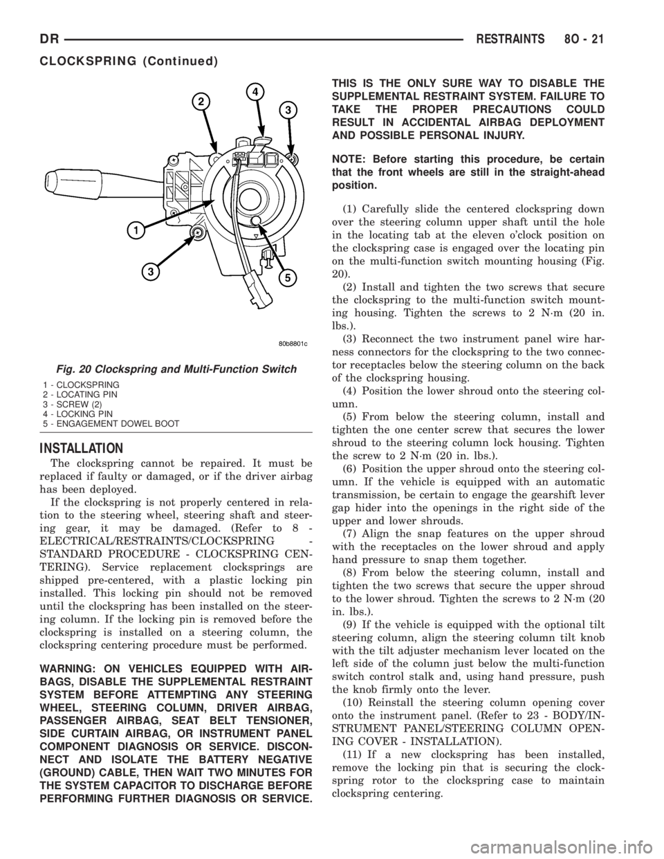
(1) Carefully slide the centered clockspring down
over the steering column upper shaft until the hole
in the locating tab at the eleven o'clock position on
the clockspring case is engaged over the locating pin
on the multi-function switch mounting housing (Fig.
20).
(2) Install and tighten the two screws that secure
the clockspring to the multi-function switch mount-
ing housing. Tighten the screws to 2 N´m (20 in.
lbs.).
(3) Reconnect the two instrument panel wire har-
ness connectors for the clockspring to the two connec-
tor receptacles below the steering column on the back
of the clockspring housing.
(4) Position the lower shroud onto the steering col-
umn.
(5) From below the steering column, install and
tighten the one center screw that secures the lower
shroud to the steering column lock housing. Tighten
the screw to 2 N´m (20 in. lbs.).
(6) Position the upper shroud onto the steering col-
umn. If the vehicle is equipped with an automatic
transmission, be certain to engage the gearshift lever
gap hider into the openings in the right side of the
upper and lower shrouds.
(7) Align the snap features on the upper shroud
with the receptacles on the lower shroud and apply
hand pressure to snap them together.
(8) From below the steering column, install and
tighten the two screws that secure the upper shroud
to the lower shroud. Tighten the screws to 2 N´m (20
in. lbs.).
(9) If the vehicle is equipped with the optional tilt
steering column, align the steering column tilt knob
with the tilt adjuster mechanism lever located on the
left side of the column just below the multi-function
switch control stalk and, using hand pressure, push
the knob firmly onto the lever.
(10) Reinstall the steering column opening cover
onto the instrument panel. (Refer to 23 - BODY/IN-
STRUMENT PANEL/STEERING COLUMN OPEN-
ING COVER - INSTALLATION).
(11) If a new clockspring has been installed,
remove the locking pin that is securing the clock-
spring rotor to the clockspring case to maintain
clockspring centering.
Fig. 20 Clockspring and Multi-Function Switch
1 - CLOCKSPRING
2 - LOCATING PIN
3 - SCREW (2)
4 - LOCKING PIN
5 - ENGAGEMENT DOWEL BOOT
DRRESTRAINTS 8O - 21
CLOCKSPRING (Continued)