2003 DODGE RAM stop
[x] Cancel search: stopPage 346 of 2895
(12) Install coolant reserve/overflow container or
degas container to fan shroud and tighten the bolts
to 8.5 N´m (75 in. lbs.).
(13) Connect upper radiator hose and install
clamp.
(14) Install battery negative cable.
(15) Fill cooling system with coolant (Refer to 7 -
COOLING - STANDARD PROCEDURE).
(16) Operate the engine until it reaches normal
operating temperature. Check cooling system fluid
levels.
RADIATOR - 5.9L DIESEL
DESCRIPTION
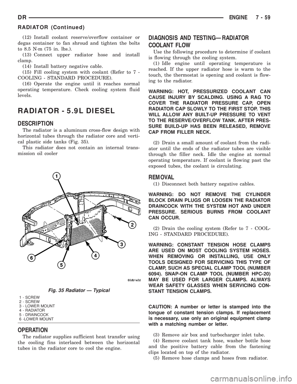
The radiator is a aluminum cross-flow design with
horizontal tubes through the radiator core and verti-
cal plastic side tanks (Fig. 35).
This radiator does not contain an internal trans-
mission oil cooler
OPERATION
The radiator supplies sufficient heat transfer using
the cooling fins interlaced between the horizontal
tubes in the radiator core to cool the engine.
DIAGNOSIS AND TESTINGÐRADIATOR
COOLANT FLOW
Use the following procedure to determine if coolant
is flowing through the cooling system.
(1) Idle engine until operating temperature is
reached. If the upper radiator hose is warm to the
touch, the thermostat is opening and coolant is flow-
ing to the radiator.
WARNING: HOT, PRESSURIZED COOLANT CAN
CAUSE INJURY BY SCALDING. USING A RAG TO
COVER THE RADIATOR PRESSURE CAP, OPEN
RADIATOR CAP SLOWLY TO THE FIRST STOP. THIS
WILL ALLOW ANY BUILT-UP PRESSURE TO VENT
TO THE RESERVE/OVERFLOW TANK. AFTER PRES-
SURE BUILD-UP HAS BEEN RELEASED, REMOVE
CAP FROM FILLER NECK.
(2) Drain a small amount of coolant from the radi-
ator until the ends of the radiator tubes are visible
through the filler neck. Idle the engine at normal
operating temperature. If coolant is flowing past the
exposed tubes, the coolant is circulating.
REMOVAL
(1) Disconnect both battery negative cables.
WARNING: DO NOT REMOVE THE CYLINDER
BLOCK DRAIN PLUGS OR LOOSEN THE RADIATOR
DRAINCOCK WITH THE SYSTEM HOT AND UNDER
PRESSURE. SERIOUS BURNS FROM COOLANT
CAN OCCUR.
(2) Drain the cooling system (Refer to 7 - COOL-
ING - STANDARD PROCEDURE).
WARNING: CONSTANT TENSION HOSE CLAMPS
ARE USED ON MOST COOLING SYSTEM HOSES.
WHEN REMOVING OR INSTALLING, USE ONLY
TOOLS DESIGNED FOR SERVICING THIS TYPE OF
CLAMP, SUCH AS SPECIAL CLAMP TOOL (NUMBER
6094). SNAP-ON CLAMP TOOL (NUMBER HPC-20)
MAY BE USED FOR LARGER CLAMPS. ALWAYS
WEAR SAFETY GLASSES WHEN SERVICING CON-
STANT TENSION CLAMPS.
CAUTION: A number or letter is stamped into the
tongue of constant tension clamps. If replacement
is necessary, use only an original equipment clamp
with a matching number or letter.
(3) Remove air box and turbocharger inlet tube.
(4) Remove coolant tank hose, washer bottle hose
and the positive battery cable from the fastening
clips located on top of the radiator.
(5) Remove hose clamps and hoses from radiator.
Fig. 35 Radiator Ð Typical
1 - SCREW
2 - SCREW
3 - LOWER MOUNT
4 - RADIATOR
5 - DRAINCOCK
6 -LOWER MOUNT
DRENGINE 7 - 59
RADIATOR (Continued)
Page 348 of 2895
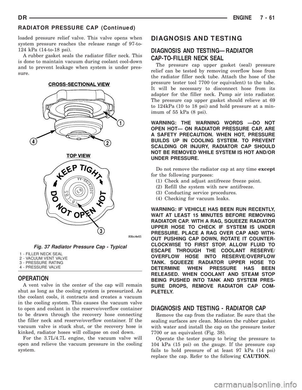
loaded pressure relief valve. This valve opens when
system pressure reaches the release range of 97-to-
124 kPa (14-to-18 psi).
A rubber gasket seals the radiator filler neck. This
is done to maintain vacuum during coolant cool-down
and to prevent leakage when system is under pres-
sure.
OPERATION
A vent valve in the center of the cap will remain
shut as long as the cooling system is pressurized. As
the coolant cools, it contracts and creates a vacuum
in the cooling system. This causes the vacuum valve
to open and coolant in the reserve/overflow container
to be drawn through the recovery hose connecting
the filler neck and reserve/overflow container. If the
vacuum valve is stuck shut, or the recovery hose is
kinked, radiator hoses will collapse on cool down.
For the 3.7L/4.7L engine, the vacuum valve will
open and relieve the vacuum pressure in the cooling
system.
DIAGNOSIS AND TESTING
DIAGNOSIS AND TESTINGÐRADIATOR
CAP-TO-FILLER NECK SEAL
The pressure cap upper gasket (seal) pressure
relief can be tested by removing overflow hose from
the radiator filler neck tube. Attach the hose of the
pressure tester tool 7700 (or equivalent) to the tube.
It will be necessary to disconnect hose from its
adapter for the filler neck. Pump air into radiator.
The pressure cap upper gasket should relieve at 69
to 124kPa (10 to 18 psi) and hold pressure at a min-
imum of 55 kPa (8 psi).
WARNING: THE WARNING WORDS ÐDO NOT
OPEN HOTÐ ON RADIATOR PRESSURE CAP, ARE
A SAFETY PRECAUTION. WHEN HOT, PRESSURE
BUILDS UP IN COOLING SYSTEM. TO PREVENT
SCALDING OR INJURY, RADIATOR CAP SHOULD
NOT BE REMOVED WHILE SYSTEM IS HOT AND/OR
UNDER PRESSURE.
Do not remove the radiator cap at any timeexcept
for the following purposes:
(1) Check and adjust antifreeze freeze point.
(2) Refill the system with new antifreeze.
(3) Conducting service procedures.
(4) Checking for vacuum leaks.
WARNING: IF VEHICLE HAS BEEN RUN RECENTLY,
WAIT AT LEAST 15 MINUTES BEFORE REMOVING
RADIATOR CAP. WITH A RAG, SQUEEZE RADIATOR
UPPER HOSE TO CHECK IF SYSTEM IS UNDER
PRESSURE. PLACE A RAG OVER CAP AND WITH-
OUT PUSHING CAP DOWN, ROTATE IT COUNTER-
CLOCKWISE TO FIRST STOP. ALLOW FLUID TO
ESCAPE THROUGH THE COOLANT RESERVE/
OVERFLOW HOSE INTO RESERVE/OVERFLOW
TANK. SQUEEZE RADIATOR UPPER HOSE TO
DETERMINE WHEN PRESSURE HAS BEEN
RELEASED. WHEN COOLANT AND STEAM STOP
BEING PUSHED INTO TANK AND SYSTEM PRES-
SURE DROPS, REMOVE RADIATOR CAP COM-
PLETELY.
DIAGNOSIS AND TESTING - RADIATOR CAP
Remove the cap from the radiator. Be sure that the
sealing surfaces are clean. Moisten the rubber gasket
with water and install the cap on the pressure tester
7700 or an equivalent (Fig. 38).
Operate the tester pump to bring the pressure to
104 kPa (15 psi) on the gauge. If the pressure cap
fails to hold pressure of at least 97 kPa (14 psi)
replace the cap. Refer to the followingCAUTION.
Fig. 37 Radiator Pressure Cap - Typical
1 - FILLER NECK SEAL
2 - VACUUM VENT VALVE
3 - PRESSURE RATING
4 - PRESSURE VALVE
DRENGINE 7 - 61
RADIATOR PRESSURE CAP (Continued)
Page 383 of 2895

Many of the electronic control modules in a vehicle
require information from the same sensing device. In
the past, if information from one sensing device was
required by several controllers, a wire from each con-
troller needed to be connected in parallel to that sen-
sor. In addition, each controller utilizing analog
sensors required an Analog/Digital (A/D) converter in
order to9read9these sensor inputs. Multiplexing
reduces wire harness complexity, sensor current
loads and controller hardware because each sensing
device is connected to only one controller, which
reads and distributes the sensor information to the
other controllers over the data bus. Also, because
each controller on the data bus can access the con-
troller sensor inputs to every other controller on the
data bus, more function and feature capabilities are
possible.
In addition to reducing wire harness complexity,
component sensor current loads and controller hard-
ware, multiplexing offers a diagnostic advantage. A
multiplex system allows the information flowing
between controllers to be monitored using a diagnos-
tic scan tool. The DaimlerChrysler system allows an
electronic control module to broadcast message data
out onto the bus where all other electronic control
modules can9hear9the messages that are being sent.
When a module hears a message on the data bus
that it requires, it relays that message to its micro-
processor. Each module ignores the messages on the
data bus that are being sent to other electronic con-
trol modules.
OPERATION
Data exchange between modules is achieved by
serial transmission of encoded data over a single wire
broadcast network. The wire colors used for the PCI
data bus circuits are yellow with a violet tracer, or
violet with a yellow tracer, depending upon the appli-
cation. The PCI data bus messages are carried over
the bus in the form of Variable Pulse Width Modu-
lated (VPWM) signals. The PCI data bus speed is an
average 10.4 Kilo-bits per second (Kbps). By compar-
ison, the prior two-wire Chrysler Collision Detection
(CCD) data bus system is designed to run at 7.8125
Kbps.
The voltage network used to transmit messages
requires biasing and termination. Each module on
the PCI data bus system provides its own biasing
and termination. Each module (also referred to as a
node) terminates the bus through a terminating
resistor and a terminating capacitor. There are two
types of nodes on the bus. The dominant node termi-
nates the bus througha1KWresistor and a 3300 pF
capacitor. The Powertrain Control Module (PCM) is
the only dominant node for the PCI data bus system.A standard node terminates the bus through an 11
KW resistor and a 330 pF capacitor.
The modules bias the bus when transmitting a
message. The PCI bus uses low and high voltage lev-
els to generate signals. Low voltage is around zero
volts and the high voltage is about seven and one-
half volts. The low and high voltage levels are gener-
ated by means of variable-pulse width modulation to
form signals of varying length. The Variable Pulse
Width Modulation (VPWM) used in PCI bus messag-
ing is a method in which both the state of the bus
and the width of the pulse are used to encode bit
information. A9zero9bit is defined as a short low
pulse or a long high pulse. A9one9bit is defined as a
long low pulse or a short high pulse. A low (passive)
state on the bus does not necessarily mean a zero bit.
It also depends upon pulse width. If the width is
short, it stands for a zero bit. If the width is long, it
stands for a one bit. Similarly, a high (active) state
does not necessarily mean a one bit. This too depends
upon pulse width. If the width is short, it stands for
a one bit. If the width is long, it stands for a zero bit.
In the case where there are successive zero or one
data bits, both the state of the bus and the width of
the pulse are changed alternately. This encoding
scheme is used for two reasons. First, this ensures
that only one symbol per transition and one transi-
tion per symbol exists. On each transition, every
transmitting module must decode the symbol on the
bus and begin timing of the next symbol. Since tim-
ing of the next symbol begins with the last transition
detected on the bus, all of the modules are re-syn-
chronized with each symbol. This ensures that there
are no accumulated timing errors during PCI data
bus communication.
The second reason for this encoding scheme is to
guarantee that the zero bit is the dominant bit on
the bus. When two modules are transmitting simul-
taneously on the bus, there must be some form of
arbitration to determine which module will gain con-
trol. A data collision occurs when two modules are
transmitting different messages at the same time.
When a module is transmitting on the bus, it is read-
ing the bus at the same time to ensure message
integrity. When a collision is detected, the module
that transmitted the one bit stops sending messages
over the bus until the bus becomes idle.
Each module is capable of transmitting and receiv-
ing data simultaneously. The typical PCI bus mes-
sage has the following four components:
²Message Header- One to three bytes in length.
The header contains information identifying the mes-
sage type and length, message priority, target mod-
ule(s) and sending module.
²Data Byte(s)- This is the actual message that
is being sent.
8E - 2 ELECTRONIC CONTROL MODULESDR
COMMUNICATION (Continued)
Page 391 of 2895

the injector pulse width by turning the ground circuit
to each individual injector on and off.
²The PCM monitors the O2S sensor input and
adjusts air-fuel ratio. It also adjusts engine idle
speed through the idle air control (IAC) motor.
²The PCM adjusts ignition timing by turning the
ground path to the coil(s) on and off.
²The PCM operates the A/C compressor clutch
through the clutch relay. This happens if A/C has
been selected by the vehicle operator and requested
by the A/C thermostat.
ACCELERATION MODE
This is an Open Loop mode. The PCM recognizes
an abrupt increase in throttle position or MAP pres-
sure as a demand for increased engine output and
vehicle acceleration. The PCM increases injector
pulse width in response to increased throttle opening.
DECELERATION MODE
When the engine is at operating temperature, this
is an Open Loop mode. During hard deceleration, the
PCM receives the following inputs.
²Air conditioning select signal (if equipped)
²Air conditioning request signal (if equipped)
²Battery voltage
²Engine coolant temperature sensor
²Crankshaft position sensor
²Intake manifold air temperature sensor
²Manifold absolute pressure (MAP) sensor
²Throttle position sensor (TPS)
²Camshaft position sensor signal
²Park/neutral switch (gear indicator signalÐauto.
trans. only)
²Vehicle speed
If the vehicle is under hard deceleration with the
proper rpm and closed throttle conditions, the PCM
will ignore the oxygen sensor input signal. The PCM
will enter a fuel cut-off strategy in which it will not
supply a ground to the injectors. If a hard decelera-
tion does not exist, the PCM will determine the
proper injector pulse width and continue injection.
Based on the above inputs, the PCM will adjust
engine idle speed through the idle air control (IAC)
motor.
The PCM adjusts ignition timing by turning the
ground path to the coil on and off.
WIDE OPEN THROTTLE MODE
This is an Open Loop mode. During wide open
throttle operation, the PCM receives the following
inputs.
²Battery voltage
²Crankshaft position sensor
²Engine coolant temperature sensor
²Intake manifold air temperature sensor
²Manifold absolute pressure (MAP) sensor²Throttle position sensor (TPS)
²Camshaft position sensor signal
During wide open throttle conditions, the following
occurs:
²Voltage is applied to the fuel injectors with the
ASD relay via the PCM. The PCM will then control
the injection sequence and injector pulse width by
turning the ground circuit to each individual injector
on and off. The PCM ignores the oxygen sensor input
signal and provides a predetermined amount of addi-
tional fuel. This is done by adjusting injector pulse
width.
²The PCM adjusts ignition timing by turning the
ground path to the coil(s) on and off.
IGNITION SWITCH OFF MODE
When ignition switch is turned to OFF position,
the PCM stops operating the injectors, ignition coil,
ASD relay and fuel pump relay.
DESCRIPTION - 5 VOLT SUPPLIES
Two different Powertrain Control Module (PCM)
five volt supply circuits are used; primary and sec-
ondary.
DESCRIPTION - IGNITION CIRCUIT SENSE
This circuit ties the ignition switch to the Power-
train Control Module (PCM).
DESCRIPTION - POWER GROUNDS
The Powertrain Control Module (PCM) has 2 main
grounds. Both of these grounds are referred to as
power grounds. All of the high-current, noisy, electri-
cal devices are connected to these grounds as well as
all of the sensor returns. The sensor return comes
into the sensor return circuit, passes through noise
suppression, and is then connected to the power
ground.
The power ground is used to control ground cir-
cuits for the following PCM loads:
²Generator field winding
²Fuel injectors
²Ignition coil(s)
²Certain relays/solenoids
²Certain sensors
DESCRIPTION - SENSOR RETURN
The Sensor Return circuits are internal to the Pow-
ertrain Control Module (PCM).
Sensor Return provides a low±noise ground refer-
ence for all engine control system sensors. Refer to
Power Grounds for more information.
8E - 10 ELECTRONIC CONTROL MODULESDR
POWERTRAIN CONTROL MODULE (Continued)
Page 398 of 2895

²The recessed Neutral Selection switch has been
depressed continuously for 4.0 seconds 100 msec
while all shift conditions have been continuously met.
²Transmission in NEUTRAL signal recognized
from the bus. (Automatic transmissions only)
²Clutch signal is recognized from the bus (Manu-
al transmissions only).
²Proper message transmissions/receptions are
occurring on the PCI bus.
²Vehicle speed is less than or equal to 4.8 km/hr
(3 miles per hour).
²Ignition key switch is in the RUN position,
engine off.
²Foot Brake is applied.
²A valid mode sensor signal is being sensed by
the TCCM.
Ashift out of transfer case Neutralwill be
allowed only if all of the following conditions are met:
²Front and rear wheel speed are within 21 km/hr
(13 mph).
²The recessed Neutral Selection switch has been
depressed continuously for 1.0 seconds 100 msec
while all shift conditions have been continuously met.
²Transmission in NEUTRAL signal recognized
from the bus.(Automatic transmissions only)
²Clutch signal is recognized from the bus (Manu-
al transmissions only).
²Proper message transmissions/receptions are
occurring on the PCI bus.
²Vehicle speed is less than or equal to 4.8 km/hr
(3 miles per hour).
²Ignition key switch is in the RUN position.
²Foot Brake is applied.
²A valid mode sensor signal is being sensed by
the TCCM.
SHIFT SEQUENCES
Once all the driver controllable conditions for the
requested shift have been met, the TCCM begins a
shift timer with a maximum duration of 1 second per
'D' channel transition. If the shift timer expires
before the TCCM recognizes to correct mode sensor
code, the shift is considered to have been blocked.
The blocked shift will increment the blocked shift
counter by one. The TCCM strategy for handling
blocked shifts will be described later. The process the
TCCM performs for the various shifts will be
described first.
RANGE AND MODE SHIFTS
The process for performing all the range and mode
shifts are the same. The following steps describe the
process.
²Allow time for Selector Switch debounce; 250
msec 50 msec.²Extinguish the source gear's LED while flashing
desired transfer case position's LED.
²Engage the shift motor for a maximum of 1 sec-
ond 100 msec per 'D' channel transition in the des-
tination gear's direction while monitoring the mode
sensor channel transitions.
²Disengage the shift motor when the correct
mode sensor code is recognized.
²Solidly illuminate the selected gear's LED.
²Transmit a bus message that the transfer case
shift is complete.
²If the desired mode sensor code is not received
after the shift timer expires (ie. a blocked or other
condition exists), stop driving the motor and wait for
200 msec 50 msec. The shift motor is then reversed
in the direction back toward the source gear for up to
1.0 seconds 100 msec. per 'D' channel. The TCCM
waits for 2.0 seconds 50 msec. and repeats the
attempt to shift to the desired position.
The exception to the preceding sequence is when a
shift from 4L to 2WD/AWD is requested. If 2WD/
AWD is requested from the 4L position, the transfer
case is first driven to the 4H position. If the 4H posi-
tion is reached, the transfer case is then driven back
to the 2WD/AWD position and the shift is considered
complete. If the transfer case does not reach any the
4H position, but is in the 2WD/AWD 'D' channel, or
the 2WD/AWD between gear position on the 4H side
of 2WD/AWD, the shift is also considered complete.
SHIFT OUT OF NEUTRAL
²Extinguish the Neutral LED.
²Engage the shift motor for a maximum of 1 sec-
ond 100 msec toward the transfer case 4H mode
position while monitoring the mode sensor channel
transitions.
²Disengage the shift motor when the correct
mode sensor code is recognized.
²Extinguish the Neutral LED.
²Transmit a bus message that the transfer case
shift is complete.
²If the desired mode sensor code is not received
after the shift timer expires (ie. a blocked or other
condition exists), stop driving the motor and wait for
200 msec 50 msec. The shift motor is then reversed
in the direction back toward the source gear for up to
1.0 seconds 100 msec. The TCCM waits for 2.0 sec-
onds 50 msec. and repeats the attempt to shift to
the desired position.
²When the Neutral button is released, if the 4H
position is the desired position, the shift is complete.
Illuminate the 4H LED.
²Otherwise when the Neutral button is released,
if all of the shift requirements are being met then
engage the shift motor towards the desired position
for 1 second 100 msec per 'D' channel. (if require-
DRELECTRONIC CONTROL MODULES 8E - 17
TRANSFER CASE CONTROL MODULE (Continued)
Page 399 of 2895

ments for shifting are not met, illuminate the 4H
LED and flash the destination LED as an indication
to the driver that all of the driver controllable shift
conditions are not being met). If this requires
another range or mode shift, begin the range/mode
shift process.
²If the desired mode sensor code is not received
after the shift timer expires (i.e. a blocked or other
condition exists), refer to the section on Blocked Shift
Strategy.
BLOCKED SHIFT STRATEGY
When a shift is commanded, the shift motor will be
driven towards its destination position, except in the
case of shifting out of Neutral if 4L was selected (the
transfer case will shift to the 4H position first, before
proceeding to 4L). If the shift is blocked on the way
to the destination, the TCCM may attempt to drive
the motor back to the original position. This process
will be allowed to occur 5 times. If the transfer case
has reached a non-NEUTRAL 'D' channel during the
shift re-attempts, the LED for the achieved gear posi-
tion is illuminated and the shift attempts are
stopped. To re-attempt the desired shift, the selector
switch will need to be rotated to the current position
until the switch debounce timer expires then a shift
will need to be requested again.
At the end of the 5th blocked attempt, the shift
motor is driven towards the last known 'D' channel
position. If this motor drive allows the transfer case
to reach the 2WD/AWD 'D' channel, or the 2WD/AWD
between gear position on the 4H side of 2WD/AWD,
the shift is considered complete and the shift
attempts are ended.
If the mode sensor is in the NEUTRAL region at
the expiration of the shift timer, the TCCM will con-
tinue to make the shift attempts according to the
blocked shift strategy independent of whether or not
the driver controlled conditions are met.
For shifts from NEUTRAL, if all 5 attempts fail to
reach the desired position (which by default is 4H),
the motor will be driven to stall in the direction of
4H or 4L, depending on the achieved position. If the
transfer case has reached the 2WD/AWD or 4L
between gear position nearest the NEUTRAL posi-
tions and the shift conditions are no longer being
met, the transfer case will be driven toward the cor-
responding 'D' channel. Otherwise, the transfer case
will be driven in the direction opposite the last
attempt with the desired target being 4H or 4L.
If the transfer case reaches the 2WD/AWD 'D'
channel when being driven in the 4H direction, then
one final 1.0 second drive toward 4H is attempted. If
the transfer case then reaches any of the 4H posi-
tions, the shift is considered complete and the 4H
LED is illuminated. If the transfer case is still the2WD/AWD position, the shift is considered complete
and the 2WD/AWD LED is illuminated.
NOTE: If after the 5th blocked shift and reversal
attempt, if the transfer case position is in the NEU-
TRAL region, shift attempts will continue until a
non-NEUTRAL 'D' channel is reached.
SHIFT REVERSAL TARGETS
If the shift timer expires (1 second per 'D' channel)
and the transfer case has not reached the desired
position, all shifts will attempt to return to their
original position with the exceptions of:
²If the intended shift is going to the High rail
from Low and can't make it, but it can make the
2WD/AWD position, the motor stops at that position.
The TCCM will not attempt to cross back over NEU-
TRAL if it does not have to. This means that there
was a block on the first attempt to go to 4H and the
transfer case has made it through NEUTRAL to a
known good position, then the motor will go back
only to the 2WD/4WD position and execute the
remainder of the attempts from there.
²For shifts out of NEUTRAL, any time a shift is
commanded out of NEUTRAL, the system needs to
get out. The TCCM should never go to NEUTRAL
unless the driver is commanding it and all required
conditions are being met
ENCODER DRIFT CORRECTION
Whenever a shift is completed, the TCCM stores
the position in memory as the transfer case's
intended position. The TCCM continuously monitors
the mode sensor and if the mode sensor drifts toward
into a NEUTRAL region sensor position for 2.0 sec-
onds, the TCCM will perform a motor drive to correct
the drift. The transfer case will be driven toward the
intended position for 1.0 seconds 100 msec. The
TCCM will wait for 2.0 seconds 50 msec. and repeat
the attempt to shift to the desired position. This will
continue until the intended position is reached.
SHIFT MOTOR BRAKING
Two modes of shift motor braking are employed to
improve shift performance, static and dynamic. Static
shift motor braking is utilized under the following
conditions:
²Whenever the transfer case is in the 2WD/AWD
or 4L 'D' channel position.
²Whenever an invalid mode sensor code is
present.
Static motor braking is achieved by applying +12V
on both shift motor wires.
NOTE: Static Shift Motor Braking is independent of
ignition key position.
8E - 18 ELECTRONIC CONTROL MODULESDR
TRANSFER CASE CONTROL MODULE (Continued)
Page 403 of 2895
LEARN A SMOOTH 1ST NEUTRAL TO DRIVE SHIFT
Perform this procedure only if the complaint is for
a delayed or harsh shift the first time the transmis-
sion is put into gear after the vehicle is allowed to
set with the engine not running for at least 10 min-
utes. Use the following steps to have the TCM learn
the 1st N-D UD CVI.
NOTE: The transmission oil temperature must be
between 80 - 110ÉF (27 - 43ÉC).
(1) Start the engine only when the engine and
ignition have been off for at least ten (10) minutes.
(2) With the vehicle at a stop and the service
brake applied, record the 1st N-D UD CVI while per-
forming a Neutral to Drive shift. The 1st N-D UD
CVI accounts for air entrapment in the UD clutch
that may occur after the engine has been off for a
period of time.
(3) Repeat Step 1 and Step 2 until the recorded 1st
N-D UD CVI value stabilizes.
NOTE: It is important that this procedure be per-
formed when the transmission temperature is
between 80 - 110ÉF (27 - 43ÉC). If this procedure
takes too long to complete fully for the allowed
transmission oil temperature, the vehicle may be
returned to the customer with an explanation that
the shift will improve daily during normal vehicle
usage. The TCM also learns at higher oil tempera-
tures, but these values (line pressure correction
values) are not available for viewing on the DRBT
III.
LEARN A SMOOTH NEUTRAL TO DRIVE GARAGE
SHIFT
Perform this procedure if the complaint is for a
delayed or harsh shift when the transmission is put
into gear after the vehicle has had its first shift. Use
the following steps to have the TCM learn the Norm
N-D UD CVI.
NOTE: The transmission oil temperature must be
between 80 - 110ÉF (27 - 43ÉC) to learn the UD CVI.
Additional learning occurs at temperatures as low
as 0ÉF and as high as 200ÉF. This procedure may be
performed at any temperature that experiences poor
shift quality. Although the UD CVI may not change,
shift quality should improve.
(1) Start the vehicle engine and shift to drive.
(2) Move the vehicle forward to a speed of at least
16 km/h (10 MPH) and come to a stop. This ensures
no air is present in the UD hydraulic circuit.
(3) Perform repeated N-D shifts at a stop while
pausing in Neutral for at least 2-3 seconds and mon-itor Norm N-D UD CVI volume until the value stabi-
lizes. The value will change during the N-D shift.
This is normal since the UD value is different for the
N-D shift then the normal value shown which is used
for 4-3 coastdown and kickdowns. Perform repeated
shifts in this temperature range until the Norm N-D
UD CVI value stabilizes and the N-D shifts become
smooth.
LEARN THE 1ST 2-3 SHIFT AFTER A RESTART OR
SHIFT TO REVERSE
Use the following steps to have the TCM learn the
1st 2-3 shift OD CVI.
NOTE: The transmission oil temperature must be
above 80ÉF (27ÉC).
(1) With the vehicle engine running, select reverse
gear for over 2 seconds.
(2) Shift the transmission to Drive and accelerate
the vehicle from a stop at a steady 15 degree throttle
opening and perform a 2-3 shift while noting the 1st
2-3 OD CVI.
(3) Repeat Step 1 and Step 2 until the 1st 2-3
upshift becomes smooth and the 1st 2-3 OD CVI sta-
bilizes.
LEARN A SMOOTH 2-3 AND 3-4 UPSHIFT
NOTE: The transmission oil temperature must be
above 110ÉF (43ÉC).
Use the following steps to have the TCM learn the
OD and 4C CVI's.
(1) Accelerate the vehicle from a stop at a steady
15 degree throttle opening and perform multiple 1-2,
2-3, and 3-4 upshifts. The 2nd 2-3 shift following a
restart or shift to reverse will be shown during the
shift as a value between the 1st 2-3 OD CVI and the
normal OD CVI. Updates to the normal OD CVI will
occur after the 2nd shift into 3rd gear, following a
restart or shift to reverse.
(2) Repeat Step 1 until the 2-3 and 3-4 shifts
become smooth and the OD and 4C CVI become sta-
ble.
LEARN A SMOOTH 4-3 COASTDOWN AND PART
THROTTLE 4-3 KICKDOWN
NOTE: The transmission oil temperature must be
above 110ÉF (43ÉC).
Use the following steps to have the TCM learn the
UD shift volume.
(1) At a vehicle speed between 64-97 km/h (40-60
MPH), perform repeated 4-3 kickdown shifts.
8E - 22 ELECTRONIC CONTROL MODULESDR
TRANSMISSION CONTROL MODULE (Continued)
Page 404 of 2895
(2) Repeat Step 1 until the UD volume becomes
somewhat stable and the shift becomes smooth.
LEARN A SMOOTH 1-2 UPSHIFT AND 3-2
KICKDOWN
Use the following steps to have the TCM learn the
2C shift volume.
NOTE: The transmission oil temperature must be
above 110ÉF (43ÉC).
(1) With a vehicle speed below 48 km/h (30 MPH)
and the transmission in 3rd gear, perform multiple
3-2 kickdowns.
(2) Repeat Step 1 until the 3-2 kickdowns become
smooth and the 2C CVI becomes stable.
LEARN A SMOOTH MANUAL 2-1 PULLDOWN
SHIFT AS WELL AS A NEUTRAL TO REVERSE
SHIFT
NOTE: The transmission oil temperature must be
above 110ÉF (43ÉC).
Use the following steps to have the TCM learn the
LR volume.
(1) With the vehicle speed around 40-48 km/h
(25-30 MPH) in Manual 2nd, perform manual pull-
downs to Low or 1st gear at closed throttle.
(2) Repeat Step 1 until the LR CVI becomes stable
and the manual 2-1 becomes smooth.
LEARN A SMOOTH NEUTRAL TO REVERSE SHIFT
NOTE: The transmission oil temperature must be
above 110ÉF (43ÉC).
(1) With the vehicle at a stop, perform Neutral to
Reverse shifts until the shift is smooth. An unlearned
Neutral to Reverse shift may be harsh or exhibit a
double bump.
(2) If any of the shifts are still not smooth after
the clutch volume stabilizes, an internal transmis-
sion problem may be present.
LEARN A SMOOTH 4-5 UPSHIFT
NOTE: The transmission oil temperature must be
above 110ÉF (43ÉC).
Use the following steps to have the TCM learn the
Alt 2C CVI.
(1) Accelerate the vehicle through 88 km/h
(55mph) at a steady 10-15 degree throttle opening
and perform multiple 4-5 upshifts.
(2) Repeat Step 1 until the 4-5 shift become
smooth and theAlt 2C CVI become stable. There is a
separate 2C volume used and learned for 4-5 shifts,
2CA. It is independent of the 2C CVI learned on 3-2
kickdowns.
DRELECTRONIC CONTROL MODULES 8E - 23
TRANSMISSION CONTROL MODULE (Continued)