2003 DODGE RAM stop
[x] Cancel search: stopPage 642 of 2895
WARNING: DURING AND FOLLOWING ANY SEAT
BELT OR CHILD RESTRAINT ANCHOR SERVICE,
CAREFULLY INSPECT ALL SEAT BELTS, BUCKLES,
MOUNTING HARDWARE, RETRACTORS, TETHER
STRAPS, AND ANCHORS FOR PROPER INSTALLA-
TION, OPERATION, OR DAMAGE. REPLACE ANY
BELT THAT IS CUT, FRAYED, OR TORN.
STRAIGHTEN ANY BELT THAT IS TWISTED.
TIGHTEN ANY LOOSE FASTENERS. REPLACE ANY
BELT THAT HAS A DAMAGED OR INOPERATIVE
BUCKLE OR RETRACTOR. REPLACE ANY BELT
THAT HAS A BENT OR DAMAGED LATCH PLATE
OR ANCHOR PLATE. REPLACE ANY CHILD
RESTRAINT ANCHOR OR THE UNIT TO WHICH THE
ANCHOR IS INTEGRAL THAT HAS BEEN BENT OR
DAMAGED. NEVER ATTEMPT TO REPAIR A SEAT
BELT OR CHILD RESTRAINT COMPONENT.
ALWAYS REPLACE DAMAGED OR FAULTY SEAT
BELT AND CHILD RESTRAINT COMPONENTS WITH
THE CORRECT, NEW AND UNUSED REPLACEMENT
PARTS LISTED IN THE DAIMLERCHRYSLER MOPAR
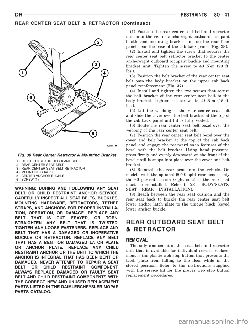
PARTS CATALOG.(1) Position the rear center seat belt and retractor
unit onto the center anchor/right outboard occupant
buckle and mounting bracket unit on the rear floor
panel near the base of the cab back panel (Fig. 38).
(2) Install and tighten the screw that secures the
rear center seat belt retractor bracket to the center
anchor/right outboard occupant buckle and mounting
bracket unit. Tighten the screw to 40 N´m (29 ft.
lbs.).
(3) Position the belt bracket of the rear center seat
belt onto the body bracket on the upper cab back
panel reinforcement (Fig. 37).
(4) Install and tighten the two screws that secure
the belt bracket of the rear center seat belt to the
body bracket. Tighten the screws to 20 N´m (15 ft.
lbs.).
(5) Lift the webbing of the rear center seat belt
and slide the cover over the belt bracket at the top of
the cab back panel until it is fully seated.
(6) Route the rear center seat belt bezel over the
webbing of the rear center seat belt.
(7) Position the rear center seat belt bezel over the
cover and belt bracket at the top of the cab back
panel and engage the rearward snap features of the
bezel with the belt bracket. Using hand pressure,
press firmly and evenly downward on the front of the
bezel until it snaps into place over the cover and belt
bracket.
(8) Reinstall the rear seat into the vehicle. On
models with the optional 60/40 split rear bench, only
the 60 percent section (right side) of the rear seat
must be reinstalled. (Refer to 23 - BODY/SEATS/
SEAT - REAR - INSTALLATION).
(9) Reach between the rear seat cushion and the
rear seat back to buckle the rear center seat belt
lower anchor latch plate to the unique black, keyed
lower anchor buckle.
REAR OUTBOARD SEAT BELT
& RETRACTOR
REMOVAL
The only component of this seat belt and retractor
unit that is available for individual service replace-
ment is the plastic web stop button that prevents the
latch plate from falling to the floor while in the
stored position. Refer to the instructions supplied
with the service kit for the proper web stop button
replacement procedures.
Fig. 38 Rear Center Retractor & Mounting Bracket
1 - RIGHT OUTBOARD OCCUPANT BUCKLE
2 - REAR CENTER SEAT BELT
3 - REAR CENTER SEAT BELT RETRACTOR
4 - MOUNTING BRACKET
5 - CENTER ANCHOR BUCKLE
6 - SCREW (1)
DRRESTRAINTS 8O - 41
REAR CENTER SEAT BELT & RETRACTOR (Continued)
Page 643 of 2895
WARNING: DURING AND FOLLOWING ANY SEAT
BELT OR CHILD RESTRAINT ANCHOR SERVICE,
CAREFULLY INSPECT ALL SEAT BELTS, BUCKLES,
MOUNTING HARDWARE, RETRACTORS, TETHER
STRAPS, AND ANCHORS FOR PROPER INSTALLA-
TION, OPERATION, OR DAMAGE. REPLACE ANY
BELT THAT IS CUT, FRAYED, OR TORN.
STRAIGHTEN ANY BELT THAT IS TWISTED.
TIGHTEN ANY LOOSE FASTENERS. REPLACE ANY
BELT THAT HAS A DAMAGED OR INOPERATIVE
BUCKLE OR RETRACTOR. REPLACE ANY BELT
THAT HAS A BENT OR DAMAGED LATCH PLATE
OR ANCHOR PLATE. REPLACE ANY CHILD
RESTRAINT ANCHOR OR THE UNIT TO WHICH THE
ANCHOR IS INTEGRAL THAT HAS BEEN BENT OR
DAMAGED. NEVER ATTEMPT TO REPAIR A SEAT
BELT OR CHILD RESTRAINT COMPONENT.
ALWAYS REPLACE DAMAGED OR FAULTY SEAT
BELT AND CHILD RESTRAINT COMPONENTS WITH
THE CORRECT, NEW AND UNUSED REPLACEMENT
PARTS LISTED IN THE DAIMLERCHRYSLER MOPAR
PARTS CATALOG.
(1) Remove the rear seat from the vehicle. (Refer
to 23 - BODY/SEATS/SEAT - REAR - REMOVAL).
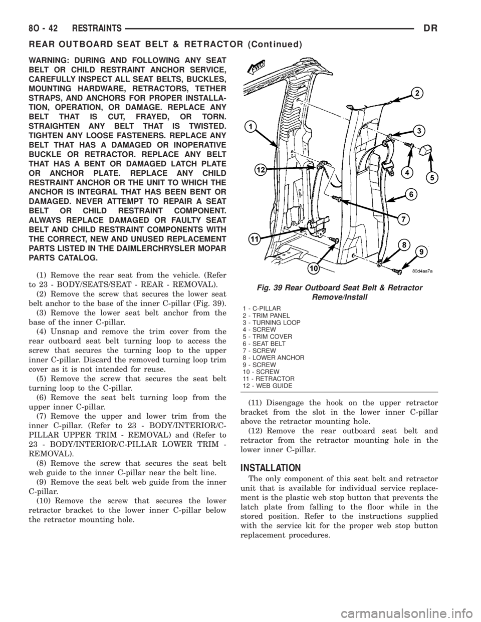
(2) Remove the screw that secures the lower seat
belt anchor to the base of the inner C-pillar (Fig. 39).
(3) Remove the lower seat belt anchor from the
base of the inner C-pillar.
(4) Unsnap and remove the trim cover from the
rear outboard seat belt turning loop to access the
screw that secures the turning loop to the upper
inner C-pillar. Discard the removed turning loop trim
cover as it is not intended for reuse.
(5) Remove the screw that secures the seat belt
turning loop to the C-pillar.
(6) Remove the seat belt turning loop from the
upper inner C-pillar.
(7) Remove the upper and lower trim from the
inner C-pillar. (Refer to 23 - BODY/INTERIOR/C-
PILLAR UPPER TRIM - REMOVAL) and (Refer to
23 - BODY/INTERIOR/C-PILLAR LOWER TRIM -
REMOVAL).
(8) Remove the screw that secures the seat belt
web guide to the inner C-pillar near the belt line.
(9) Remove the seat belt web guide from the inner
C-pillar.
(10) Remove the screw that secures the lower
retractor bracket to the lower inner C-pillar below
the retractor mounting hole.(11) Disengage the hook on the upper retractor
bracket from the slot in the lower inner C-pillar
above the retractor mounting hole.
(12) Remove the rear outboard seat belt and
retractor from the retractor mounting hole in the
lower inner C-pillar.
INSTALLATION
The only component of this seat belt and retractor
unit that is available for individual service replace-
ment is the plastic web stop button that prevents the
latch plate from falling to the floor while in the
stored position. Refer to the instructions supplied
with the service kit for the proper web stop button
replacement procedures.
Fig. 39 Rear Outboard Seat Belt & Retractor
Remove/Install
1 - C-PILLAR
2 - TRIM PANEL
3 - TURNING LOOP
4 - SCREW
5 - TRIM COVER
6 - SEAT BELT
7 - SCREW
8 - LOWER ANCHOR
9 - SCREW
10 - SCREW
11 - RETRACTOR
12 - WEB GUIDE
8O - 42 RESTRAINTSDR
REAR OUTBOARD SEAT BELT & RETRACTOR (Continued)
Page 662 of 2895
5.9L Diesel Engines With Automatic Trans.
If equipped with a diesel powered engine and an
automatic transmission, an electric vacuum pump
and vacuum lines are used to supply vacuum to the
speed control servo. A vacuum reservoir is not used.
DIAGNOSIS AND TESTING - ROAD TEST
Perform a vehicle road test to verify reports of
speed control system malfunction. The road test
should include attention to the speedometer. Speed-
ometer operation should be smooth and without flut-
ter at all speeds.
Flutter in the speedometer indicates a problem
which might cause surging in the speed control sys-
tem. The cause of any speedometer problems should
be corrected before proceeding. Refer to Instrument
Cluster for speedometer diagnosis.
If a road test verifies a system problem and the
speedometer operates properly, check for:
²A Diagnostic Trouble Code (DTC). If a DTC
exists, conduct tests per the Powertrain Diagnostic
Procedures service manual.
²A misadjusted brake (stop) lamp switch. This
could also cause an intermittent problem.²Loose, damaged or corroded electrical connec-
tions at the servo (if used). Corrosion should be
removed from electrical terminals and a light coating
of Mopar MultiPurpose Grease, or equivalent,
applied.
²Leaking vacuum reservoir (if used).
²Loose or leaking vacuum hoses or connections (if
used).
²Defective one-way vacuum check valve (if used).
²Secure attachment of both ends of the speed con-
trol servo cable (if used).
²Smooth operation of throttle linkage (if used)
and throttle body air valve.
²Failed speed control servo (if used). Do the servo
vacuum test.
CAUTION: When test probing for voltage or conti-
nuity at electrical connectors, care must be taken
not to damage connector, terminals or seals. If
these components are damaged, intermittent or
complete system failure may occur.
SPECIFICATIONS
TORQUE - SPEED CONTROL
DESCRIPTION N-m Ft. Lbs. In. Lbs.
Servo Mounting Bracket-
to-Servo Nuts7-60
Servo Mounting Bracket-
to-Battery Tray Screws4-30
Speed Control Switch
Mounting Screws1.7 - 15
Vacuum Reservoir
Mounting Nuts3-20
CABLE
DESCRIPTION
The speed control servo cable is connected between
the speed control vacuum servo diaphragm and the
throttle body control linkage. This cable is used with
3.7L/4.7L/5.9L/8.0L gas powered engines only. It is
also used if equipped with a 5.9L diesel engine
equipped with an automatic transmission.
A speed control servo cableis not usedif equipped
with either a 5.9L diesel engine equipped with a
manual transmission, or any 5.7L engine/transmis-
sion combinations.
OPERATION
This cable causes the throttle control linkage to
open or close the throttle valve in response to move-
ment of the vacuum servo diaphragm.
REMOVAL
3.7L / 4.7L GAS
(1) Disconnect negative battery cable at battery.
(2) Remove air intake tube at top of throttle body.
The accelerator cable must be partially removed to
gain access to speed control cable.
DRSPEED CONTROL 8P - 3
SPEED CONTROL (Continued)
Page 673 of 2895
NOTE: If a PCM is replaced, the unique ªSecret
Keyº data must be transferred from the SKIM to the
PCM. This procedure requires the SKIM to be
placed in SECURED ACCESS MODE using the four
digit PIN code.
SENTRY KEY IMMOBILIZER SYSTEM
TRANSPONDER PROGRAMMING
Two programmed Sentry Key transponders are
included with the Sentry Key Immobilizer System
(SKIS) when it is shipped from the factory. The Sen-
try Key Immobilizer Module (SKIM) can be pro-
grammed to recognize up to six additional
transponders, for a total of eight Sentry Keys. The
following ªCustomer Learnº programming procedure
for the programming of additional transponders
requires access to at least two of the valid Sentry
Keys. If two valid Sentry Keys are not available, Sen-
try Key programming will require the use of a
DRBIIItscan tool.
CUSTOMER LEARN PROGRAMMING
(1) Obtain the additional Sentry Key transponder
blank(s) that are to be programmed for the vehicle.
Cut the additional Sentry Key transponder blanks to
match the ignition lock cylinder mechanical key
codes.
(2) Insert one of the two valid Sentry Key tran-
sponders into the ignition switch and turn the igni-
tion switch to the ON position.
(3) After the ignition switch has been in the ON
position for about three seconds, but no more than
fifteen seconds, cycle the ignition switch back to the
OFF position. Replace the first valid Sentry Key in
the ignition lock cylinder with the second valid Sen-
try Key and turn the ignition switch back to the ON
position. Both operations must be performed within
15 seconds.
(4) In approximately ten seconds the VTSS indica-
tor LED will start to flash to indicate that the sys-
tem has entered the ªCustomer Learnº programming
mode.
(5) Within approximately sixty seconds of entering
the ªCustomer Learnº programming mode, turn the
ignition switch to the OFF position, replace the valid
Sentry Key with a blank Sentry Key transponder,
and turn the ignition switch back to the ON position.
(6) In approximately ten seconds, the VTSS indica-
tor LED will stop flashing and stay on solid for
approximately three seconds and then turn OFF to
indicate that the blank Sentry Key transponder has
been successfully programmed. The SKIS will imme-
diately return to normal system operation following
exit from the ªCustomer Learnº programming mode.(7) Repeat this process for each additional Sentry
Key transponder blank to be programmed.
If any of the above steps is not completed in the
proper sequence, or within the allotted time, the
SKIS will automatically exit the ªCustomer Learnº
programming mode. The SKIS will also automatically
exit the ªCustomer Learnº programming mode if it
sees a non-blank Sentry Key transponder when it
should see a blank, if it has already programmed
eight valid Sentry Keys, or if the ignition switch is
turned to the OFF position for more than about fifty
seconds.
NOTE: While in Customer Learn mode (LED flash-
ing), the engine will not START and RUN.
PROGRAMMING BLANK SENTRY KEY
TRANSPONDERS WITH A DRBIIITSCAN TOOL
When programming a blank Sentry Key transpon-
der, the key blank must first be cut to match the
ignition lock cylinder. It will also be necessary to
enter the vehicle's four digit PIN code into the
DRBIIItscan tool to enter the Sentry Key Immobi-
lizer Module's (SKIM's) secured access mode.
NOTE: Once a Sentry Key is programmed to a par-
ticular vehicle, it cannot be transferred to another
vehicle.
Insert the blank key into the ignition and turn it to
the RUN position. Using the DRBIIItscan tool,
select ªTheft Alarm,º then ªSKIM,º then ªMiscella-
neous.º Select ªProgram New Key.º Enter the four
digit PIN code using the DRBIIIt. When program-
ming is completed, the SKIM will exit secured access
mode and the DRBIIItwill display the status of the
key. One of five different status messages may be dis-
played as follows:
²ªProgramming Successfulº is displayed if SKIM
Sentry Key programming succeeds.
²ªLearned Key in Ignitionº is displayed if the key
in the ignition has already been programmed into
that vehicle's SKIM.
²ª8 Keys Already Learned (At The Maximum)
Programming Not Doneº is displayed if eight keys
have already been programmed into the SKIM. In
this case, if a new key needs to be added due to a
lost or defective key, the ªErase All Keysº function
(requires entering secured access mode) has to be
performed. Then the customer's seven keys plus the
new key MUST be reprogrammed into the SKIM.
²ªProgramming Not Attemptedº is displayed after
an ªErase All Keysº function is executed.
²ªProgramming Key Failedº is displayed if fur-
ther diagnosis is required.
8Q - 4 VEHICLE THEFT SECURITYDR
VEHICLE THEFT SECURITY (Continued)
Page 683 of 2895
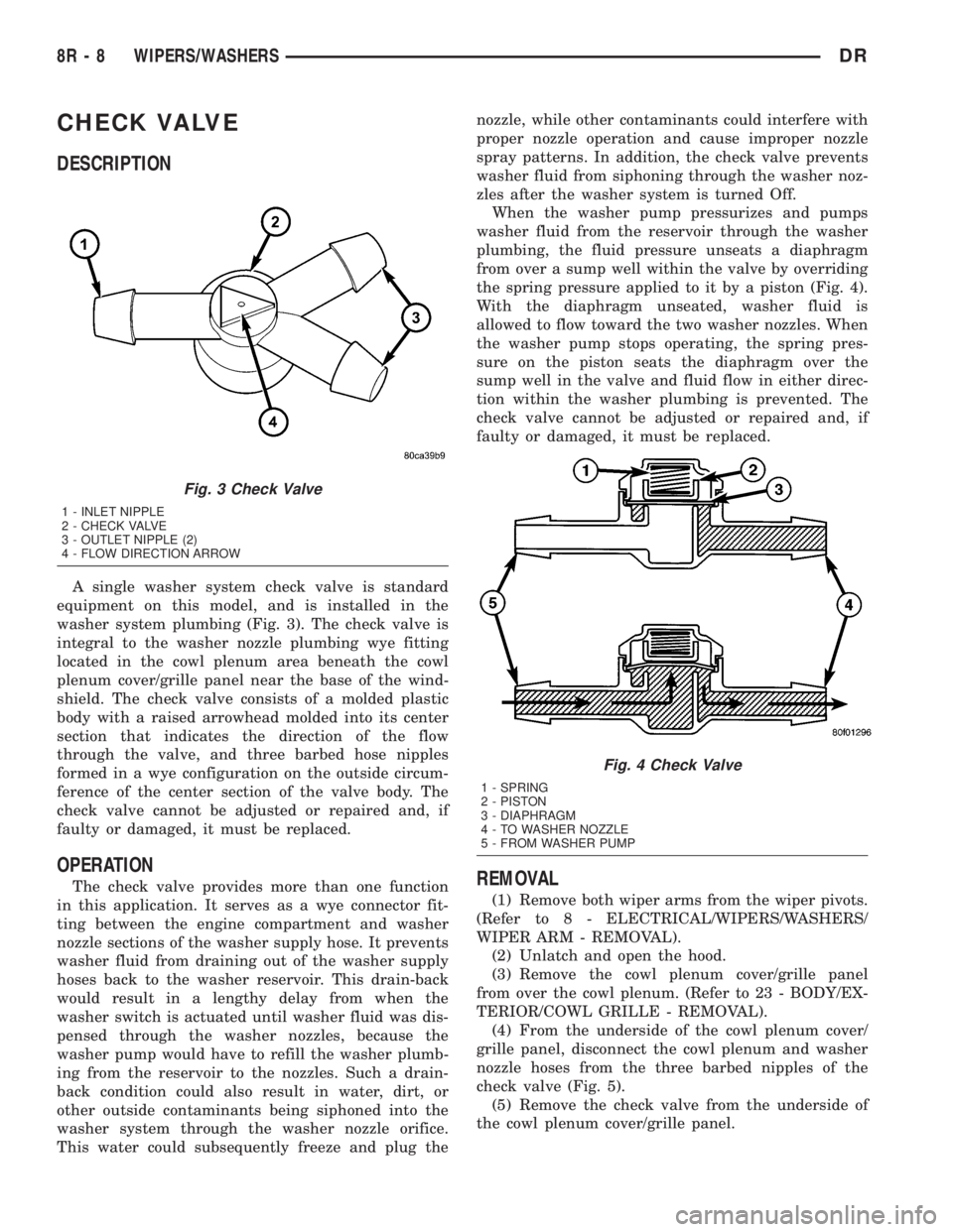
CHECK VALVE
DESCRIPTION
A single washer system check valve is standard
equipment on this model, and is installed in the
washer system plumbing (Fig. 3). The check valve is
integral to the washer nozzle plumbing wye fitting
located in the cowl plenum area beneath the cowl
plenum cover/grille panel near the base of the wind-
shield. The check valve consists of a molded plastic
body with a raised arrowhead molded into its center
section that indicates the direction of the flow
through the valve, and three barbed hose nipples
formed in a wye configuration on the outside circum-
ference of the center section of the valve body. The
check valve cannot be adjusted or repaired and, if
faulty or damaged, it must be replaced.
OPERATION
The check valve provides more than one function
in this application. It serves as a wye connector fit-
ting between the engine compartment and washer
nozzle sections of the washer supply hose. It prevents
washer fluid from draining out of the washer supply
hoses back to the washer reservoir. This drain-back
would result in a lengthy delay from when the
washer switch is actuated until washer fluid was dis-
pensed through the washer nozzles, because the
washer pump would have to refill the washer plumb-
ing from the reservoir to the nozzles. Such a drain-
back condition could also result in water, dirt, or
other outside contaminants being siphoned into the
washer system through the washer nozzle orifice.
This water could subsequently freeze and plug thenozzle, while other contaminants could interfere with
proper nozzle operation and cause improper nozzle
spray patterns. In addition, the check valve prevents
washer fluid from siphoning through the washer noz-
zles after the washer system is turned Off.
When the washer pump pressurizes and pumps
washer fluid from the reservoir through the washer
plumbing, the fluid pressure unseats a diaphragm
from over a sump well within the valve by overriding
the spring pressure applied to it by a piston (Fig. 4).
With the diaphragm unseated, washer fluid is
allowed to flow toward the two washer nozzles. When
the washer pump stops operating, the spring pres-
sure on the piston seats the diaphragm over the
sump well in the valve and fluid flow in either direc-
tion within the washer plumbing is prevented. The
check valve cannot be adjusted or repaired and, if
faulty or damaged, it must be replaced.REMOVAL
(1) Remove both wiper arms from the wiper pivots.
(Refer to 8 - ELECTRICAL/WIPERS/WASHERS/
WIPER ARM - REMOVAL).
(2) Unlatch and open the hood.
(3) Remove the cowl plenum cover/grille panel
from over the cowl plenum. (Refer to 23 - BODY/EX-
TERIOR/COWL GRILLE - REMOVAL).
(4) From the underside of the cowl plenum cover/
grille panel, disconnect the cowl plenum and washer
nozzle hoses from the three barbed nipples of the
check valve (Fig. 5).
(5) Remove the check valve from the underside of
the cowl plenum cover/grille panel.
Fig. 3 Check Valve
1 - INLET NIPPLE
2 - CHECK VALVE
3 - OUTLET NIPPLE (2)
4 - FLOW DIRECTION ARROW
Fig. 4 Check Valve
1 - SPRING
2 - PISTON
3 - DIAPHRAGM
4 - TO WASHER NOZZLE
5 - FROM WASHER PUMP
8R - 8 WIPERS/WASHERSDR
Page 720 of 2895

8W-02 COMPONENT INDEX
Component Page
4WD Switch......................... 8W-30
A/C Compressor Clutch Relay............ 8W-42
A/C Compressor Clutch................. 8W-42
A/C Pressure Transducer................ 8W-42
A/C-Heater Control.................... 8W-42
Accelerator Pedal Position Sensor......... 8W-30
Adjustable Pedal Motor................. 8W-30
Adjustable Pedal Relay................. 8W-30
Adjustable Pedal Switch................ 8W-30
Airbag Control Modules................ 8W-43
Airbags............................. 8W-43
Ambient Temperature Sensor............ 8W-49
Amplifier Audio....................... 8W-47
Auto Shut Down Relay................. 8W-30
Automatic Day/Night Mirror............. 8W-49
Auxiliary Battery..................... 8W-20
Backup Lamp Switch.................. 8W-51
Battery Temperature Sensor............. 8W-30
Battery............................. 8W-20
Blend Door Actuator................... 8W-42
Blower Motor Resistor Block............. 8W-42
Blower Motor......................... 8W-42
Brake Lamp Switch.................... 8W-33
Brake Transmission Shift Interlock
Solenoid........................... 8W-40
Camshaft Position Sensor............... 8W-30
Capacitor............................ 8W-30
Center High Mounted Stop Lamp/Cargo
Lamp.......................... 8W-44, 51
Center High Mounted Stop Lamp-
Aftermarket..................... 8W-33, 51
Cigar Lighter Outlet................... 8W-41
Circuit Breaker....................... 8W-10
Clearance Lamps...................... 8W-50
Clockspring................. 8W-33, 41, 43, 47
Clutch Interlock Brake Switch........... 8W-21
Coil On Plugs........................ 8W-30
Compass/Mini-Trip Computer............ 8W-49
Condenser Fan Relay.................. 8W-42
Condenser Fan....................... 8W-42
Controller Antilock Brake............ 8W-34, 35
Crankshaft Position Sensor.............. 8W-30
Cylinder Lock Switch-Driver............. 8W-61
Cylinder Lock Switch-Passenger.......... 8W-61
Data Link Connector................... 8W-18
Data Link Connector-Engine............. 8W-18
Dome Lamp.......................... 8W-44
Door Ajar Switches.................... 8W-40
Door Lock Motor/Ajar Switches........ 8W-40, 61
Door Lock Switch-Passenger............. 8W-61
Driver Door Module.............. 8W-60, 61, 62
Electric Brake Provision............. 8W-33, 54Component Page
Electronic Throttle Control Module........ 8W-30
Engine Control Module................. 8W-30
Engine Coolant Temperature Sensor....... 8W-30
Engine Oil Pressure Switch.............. 8W-30
EVAP/Purge Solenoid.................. 8W-30
Evaporator Temperature Sensor.......... 8W-42
Fender Lamps........................ 8W-51
Fog Lamp Relay...................... 8W-50
Fog Lamps.......................... 8W-50
Front Control Module.................. 8W-10
Fuel Heater Relay..................... 8W-30
Fuel Heater.......................... 8W-30
Fuel Injectors........................ 8W-30
Fuel Injector Packs.................... 8W-30
Fuel Pump Module.................... 8W-30
Fuel Pump Motor..................... 8W-30
Fuel Pump Relay...................... 8W-30
Fuel Rail Pressure Sensor............... 8W-30
Fuses............................... 8W-10
Fusible Link......................... 8W-10
Grounds............................ 8W-15
Generator........................... 8W-20
Glove Box Lamp And Switch............. 8W-44
Headlamp Switch.................. 8W-40, 50
Headlamps.......................... 8W-50
Heated Mirror Relay................... 8W-62
Heated Seat Cushions.................. 8W-63
Heated Seat Switches.................. 8W-63
Horn Relay.......................... 8W-41
Horn Switch......................... 8W-41
Horns.............................. 8W-41
Idle Air Control Motor............ 8W-30, 30-36
Ignition Coils......................... 8W-30
Ignition Switch....................... 8W-10
Inlet Air Temperature/Pressure Sensor..... 8W-30
Input Speed Sensor.................... 8W-31
Instrument Cluster.................... 8W-40
Intake Air Heater Relays............... 8W-30
Intake Air Temperature Sensor........... 8W-30
Intake Air Temperature/Manifold Absolute
Pressure Sensor..................... 8W-30
Integrated Power Module............... 8W-10
Knock Sensors........................ 8W-30
Leak Detection Pump.................. 8W-30
License Lamps....................... 8W-51
Lift Pump Motor...................... 8W-30
Line Pressure Sensor................ 8W-30, 31
Lumbar Motors....................... 8W-63
Manifold Absolute Pressure Sensor........ 8W-30
Mode Door Actuators................... 8W-42
Multi-Function Switch............ 8W-40, 52, 53
Output Speed Sensor................... 8W-31
DR8W-02 COMPONENT INDEX 8W - 02 - 1
Page 721 of 2895

Component Page
Overdrive Switch...................... 8W-31
Overhead Map/Reading Lamp............ 8W-44
Oxygen Sensors....................... 8W-30
Oxygen Sensor Downstream Relay........ 8W-30
Park Brake Switch.................... 8W-40
Park Lamp Relay................... 8W-50, 52
Park/Turn Signal Lamps............. 8W-50, 52
Passenger Airbag On/Off Switch.......... 8W-43
Blend Door Actuators.................. 8W-42
Passenger Lumbar Switch............... 8W-63
Power Mirrors........................ 8W-62
Power Outlet......................... 8W-41
Power Outlet-Console.................. 8W-41
Power Seat Motors.................... 8W-63
Power Seat Switches................... 8W-63
Power Steering Pressure Switch.......... 8W-30
Power Window Circuit Breaker........... 8W-10
Power Window Motors.................. 8W-60
Power Window Switches................ 8W-60
Powertrain Control Module.............. 8W-30
PTCs............................... 8W-10
PTO Switch.......................... 8W-30
Radio............................... 8W-47
Recirculation Door Actuator............. 8W-42
Red Brake Warning Indicator Switch . . . 8W-34, 35
Remote Radio Switches................. 8W-47
Splices.............................. 8W-70
Seat Belt Pretensioners................. 8W-43
Seat Belt Switch-Driver................ 8W-40
Seat Belt Tensioner Reducer............. 8W-40
Seat Heater Interface Module............ 8W-63
Sentry Key Immobilizer Module.......... 8W-39
Spare Relay.......................... 8W-10
Speakers............................ 8W-47Component Page
Speed Control Servo................... 8W-33
Speed Control Switches................. 8W-33
Starter Motor Relay................... 8W-21
Starter Motor.................... 8W-21, 21-3
Tail/Stop Lamps...................... 8W-52
Tail/Stop/Turn Signal Lamps.......... 8W-51, 52
Tail/Turn Lamps...................... 8W-52
Tailgate Lamp Assembly................ 8W-51
Throttle Position Sensor................ 8W-30
Throttle Position Switch................ 8W-30
Trailer Tow Connector.................. 8W-54
Trailer Tow Connector-Add On........... 8W-54
Trailer Tow Left Turn Relay............. 8W-54
Trailer Tow Right Turn Relay............ 8W-54
Transfer Case Control Module............ 8W-31
Transfer Case Mode Sensor.............. 8W-31
Transfer Case Selector Switch............ 8W-31
Transfer Case Shift Motor............... 8W-31
Transmission Control Module............ 8W-31
Transmission Control Relay............. 8W-31
Transmission Range Sensor.............. 8W-31
Transmission Solenoid Assembly.......... 8W-31
Transmission Solenoid/TRS Assembly...... 8W-31
Underhood Lamp...................... 8W-44
Vacuum Pump........................ 8W-30
Vehicle Speed Sensor................... 8W-30
Vistronic Fan Drive.................... 8W-30
Washer Fluid Level Switch.............. 8W-53
Washer Pump Motor-Front.............. 8W-53
Water In Fuel Sensor.................. 8W-30
Wheel Speed Sensors................... 8W-35
Wiper High/Low Relay................. 8W-53
Wiper Motor-Front.................... 8W-53
8W - 02 - 2 8W-02 COMPONENT INDEXDR
Page 722 of 2895

8W-10 POWER DISTRIBUTION
Component PageA/C Compressor Clutch....................8W-10-16, 43, 44
A/C Compressor Clutch Relay.................8W-10-16, 43, 44
A/C-Heater Control......................8W-10-46, 47, 58
Adjustable Pedal Relay......................8W-10-14, 34
Adjustable Pedal Switch.................8W-10-14, 34, 46, 58
Airbag Control Module......................8W-10-46, 48
Airbag Control Module-Left Side Impact...............8W-10-46
Airbag Control Module-Right Side Impact..............8W-10-46
Ambient Temperature Sensor...................8W-10-52, 54
Amplifier Audio...........................8W-10-33
Auto Shut Down Relay......................8W-10-11, 18
Automatic Day/Night Mirror...................8W-10-45, 52
Auxiliary Battery...........................8W-10-11
Backup Lamp Switch.......................8W-10-48, 53
Battery..............................8W-10-11, 18
Blower Motor.............................8W-10-56
Brake Lamp Switch....................8W-10-13, 32, 43, 44
Capacitor.............................8W-10-21, 23
Center High Mounted Stop Lamp/Cargo Lamp............8W-10-42
Cigar Lighter Outlet.........................8W-10-50
Circuit Breaker............................8W-10-56
Clearance Lamp No. 1........................8W-10-37
Clearance Lamp No. 2........................8W-10-37
Clearance Lamp No. 3........................8W-10-37
Clearance Lamp No. 4........................8W-10-37
Clearance Lamp No. 5........................8W-10-37
Clutch Interlock Brake Switch....................8W-10-39
Coil On Plug No. 1........................8W-10-19, 22
Coil On Plug No. 2........................8W-10-20, 21
Coil On Plug No. 3........................8W-10-19, 22
Coil On Plug No. 4........................8W-10-20, 21
Coil On Plug No. 5........................8W-10-19, 22
Coil On Plug No. 6........................8W-10-20, 21
Coil On Plug No. 7........................8W-10-19, 22
Coil On Plug No. 8........................8W-10-20, 21
Compass/Mini-Trip Computer...................8W-10-42, 45
Condenser Fan..........................8W-10-17, 49
Condenser Fan Relay.......................8W-10-17, 49
Controller Antilock Brake...................8W-10-13, 30, 48
Data Link Connector.......................8W-10-32, 54
Dome Lamp.............................8W-10-42
Door Lock Switch-Passenger.....................8W-10-45
Driver Door Module.......................8W-10-42, 56
Electric Brake Provision.......................8W-10-18
Engine Control Module........................8W-10-43
EVAP/Purge Solenoid.........................8W-10-45
Fender Lamp-Front Left.......................8W-10-37
Fender Lamp-Front Right......................8W-10-37
Fender Lamp-Rear Left.......................8W-10-37
Fender Lamp-Rear Right.......................8W-10-37
Fog Lamp Relay.........................8W-10-15, 38
Fog Lamp-Left............................8W-10-38
Fog Lamp-Right...........................8W-10-38
Front Control Module....8W-10-12, 31, 32, 34, 35, 36, 48, 45, 51, 52, 54 , 55
Fuel Heater.............................8W-10-57
Fuel Heater Relay........................8W-10-17, 57
Fuel Injector No. 1........................8W-10-22, 24
Fuel Injector No. 2....................8W-10-20, 21, 23, 24
Fuel Injector No. 3........................8W-10-22, 24
Fuel Injector No. 4....................8W-10-20, 21, 23, 24
Fuel Injector No. 5........................8W-10-22, 24
Fuel Injector No. 6....................8W-10-20, 21, 23, 24
Fuel Injector No. 7........................8W-10-22, 24
Fuel Injector No. 8....................8W-10-20, 21, 23, 24
Fuel Injector No. 9..........................8W-10-24
Fuel Injector No. 10.........................8W-10-23
Fuel Pump Module........................8W-10-16, 42
Fuel Pump Relay.....................8W-10-16, 42, 43, 44
Fuse 1..............................8W-10-11, 18
Fuse 2............................8W-10-11, 12, 18
Fuse 3..............................8W-10-12, 26
Fuse 4..............................8W-10-12, 26
Fuse 5.......................8W-10-11, 12, 13, 27, 28, 29
Fuse 6............................8W-10-12, 13, 30
Fuse 7..............................8W-10-13, 30
Fuse 8..............................8W-10-14, 31
Fuse 9..............................8W-10-12, 26
Fuse 10..............................8W-10-12, 26
Fuse 11............................8W-10-12, 13, 32
Fuse 12............................8W-10-17, 49, 57
Fuse 13..............................8W-10-12, 32
Fuse 14..............................8W-10-14, 39
Fuse 15............................8W-10-15, 16, 36
Fuse 16............................8W-10-16, 43, 44
Fuse 17............................8W-10-16, 17, 42
Fuse 18..............................8W-10-13, 32
Fuse 19..............................8W-10-13, 33
Fuse 20..............................8W-10-12, 26
Fuse 21..............................8W-10-13, 33
Fuse 22..............................8W-10-13, 33
Fuse 24..............................8W-10-13, 32
Fuse 25..............................8W-10-13, 33
Fuse 27............................8W-10-16, 17, 47
Fuse 28............................8W-10-43, 44, 45
Fuse 32..............................8W-10-16, 36
Fuse 33..............................8W-10-16, 36Component PageFuse 34..............................8W-10-16, 36
Fuse 35...............................8W-10-48
Fuse 36..............................8W-10-47, 58
Fuse 37...............................8W-10-48
Fuse 38..............................8W-10-47, 48
Fuse 40............................8W-10-14, 15, 34
Fuse 41..............................8W-10-15, 38
Fuse 42..............................8W-10-13, 34
Fuse 43..............................8W-10-13, 34
Fuse 45............................8W-10-15, 16, 38
Fuse 46............................8W-10-14, 15, 35
Fuse 47..............................8W-10-15, 35
Fuse 48..............................8W-10-14, 34
Fuse 49..............................8W-10-11, 18
Fuse 50...............................8W-10-45
Fuse 51............................8W-10-13, 14, 32
Fuse 52..............................8W-10-47, 48
Fuse 53...............................8W-10-45
Fusible Link.............................8W-10-11
G103...............................8W-10-51, 52
G106...........................8W-10-31, 51, 55, 57
G107...............................8W-10-27, 29
G201.................................8W-10-26
Generator.............................8W-10-11, 28
Glove Box Lamp And Switch.....................8W-10-42
Headlamp Switch..........................8W-10-38
Headlamp-Left............................8W-10-55
Headlamp-Right...........................8W-10-55
Heated Mirror Relay.......................8W-10-17, 47
Horn Relay............................8W-10-15, 38
Horn-High Note...........................8W-10-38
Horn-Low Note............................8W-10-38
Ignition Coil.............................8W-10-24
Ignition Coil-Left...........................8W-10-23
Ignition Coil-Right..........................8W-10-23
Ignition Switch................8W-10-12, 26, 39, 45, 48, 50, 56
Instrument Cluster................8W-10-13, 26, 32, 33, 45, 50
Integrated Power Module . 8W-10-2, 3, 5, 11, 12, 13,, 14, 15, 16, 17, 18, 26, 27,
28, 29, 30, 31, 32, 33, 34, 35, 36, 38, 39, 42, 43, 44, 45, 46, 47, 48, 49, 50, 52,
54, 55, 57, 58
Leak Detection Pump........................8W-10-28
License Lamp-Left..........................8W-10-36
License Lamp-Right.........................8W-10-37
Overhead Map/Reading Lamp....................8W-10-42
Oxygen Sensor 1/1 Upstream.....................8W-10-25
Oxygen Sensor 1/2 Downstream...................8W-10-25
Oxygen Sensor 2/1 Upstream.....................8W-10-25
Oxygen Sensor 2/2 Downstream...................8W-10-25
Oxygen Sensor Downstream Relay................8W-10-11, 18
Park Lamp Relay.........................8W-10-16, 36
Park/Turn Signal Lamp-Left Front................8W-10-36, 51
Park/Turn Signal Lamp-Right Front...............8W-10-36, 51
Passenger Airbag On/Off Switch...................8W-10-46
Passenger Lumbar Switch......................8W-10-30
Power Mirror-Left..........................8W-10-47
Power Mirror-Right.........................8W-10-47
Power Outlet...........................8W-10-13, 33
Power Outlet-Console........................8W-10-34
Power Seat Switch-Driver......................8W-10-30
Power Seat Switch-Passenger....................8W-10-30
Power Window Circuit Breaker....................8W-10-56
Powertrain Control Module . 8W-10-17, 18, 19, 21, 23, 24, 28, 29, 33, 39, 40, 41,
42, 43, 44, 49, 57
PTCNo.1.........................8W-10-42, 43, 44, 45
PTCNo.2 ..............................8W-10-50
PTCNo.5 ..............................8W-10-35
Radio...............................8W-10-32, 50
Seat Belt Tensioner Reducer.....................8W-10-50
Seat Heater Interface Module....................8W-10-34
Sentry Key Immobilizer Module...............8W-10-33, 43, 44
Spare Relay.............................8W-10-58
Starter Motor...........................8W-10-14, 39
Starter Motor Relay.......................8W-10-14, 39
Tail/Stop/Turn Signal Lamp-Left.............8W-10-36, 51, 52, 54
Tail/Stop/Turn Signal Lamp-Right.............8W-10-37, 51, 52, 54
Tailgate Lamp Assembly.....................8W-10-36, 41
Trailer Tow Connector...................8W-10-15, 16, 35, 36
Trailer Tow Connector-Add On..............8W-10-18, 35, 36, 52
Trailer Tow Left Turn Relay...................8W-10-15, 35
Trailer Tow Right Turn Relay...................8W-10-15, 35
Transfer Case Control Module................8W-10-13, 34, 39
Transmission Control Module...............8W-10-12, 27, 41, 56
Transmission Control Relay................8W-10-12, 27, 28, 29
Transmission Range Sensor..................8W-10-40, 48, 53
Transmission Solenoid Assembly.................8W-10-12, 28
Transmission Solenoid/TRS Assembly.........8W-10-27, 29, 40, 48, 53
Underhood Lamp...........................8W-10-32
Vacuum Pump............................8W-10-43
Vistronic Fan Drive.........................8W-10-58
Washer Fluid Level Switch....................8W-10-52, 54
Washer Pump Motor-Front......................8W-10-52
Wiper High/Low Relay......................8W-10-14, 31
Wiper Motor-Front........................8W-10-31, 52
Wiper On/Off Relay........................8W-10-14, 31
DR8W-10 POWER DISTRIBUTION 8W - 10 - 1