2003 DODGE RAM steering
[x] Cancel search: steeringPage 122 of 2895

(6) Position upper and lower suspension arms in
the axle brackets. Install bolts, nuts and align the
suspension alignment cams to the reference marks.
Do not tighten at this time.
(7) Connect track bar to the axle bracket and
install the bolt. Do not tighten at this time.
(8) Install shock absorber and tighten bolts to 121
N´m (89 ft. lbs.).
(9) Install stabilizer bar link to the axle bracket.
Tighten the nut to 68 N´m (50 ft. lbs.).
(10) Install drag link and tie rod to the steering
knuckles and tighten the nuts to 108 N´m (80 ft.
lbs.).
(11) Install ABS wheel speed sensors.
(12) Install rotors and brake calipers.
(13) Connect the axle vent hose.
(14) Install front propeller shaft.
(15) Check and add differential lubricant, if neces-
sary.
(16) Install wheel and tire assemblies.
(17) Remove lower the vehicle.
(18) Tighten upper suspension arm nuts at axle to
149 N´m (110 ft. lbs.). Tighten upper suspension arm
nuts at frame to 149 N´m (110 ft. lbs.).
(19) Tighten lower suspension arm nuts at axle to
190 N´m (140 ft. lbs.). Tighten the lower suspension
arm nuts at frame to 190 N´m (140 ft. lbs.).
(20) Tighten track bar bolt at the axle bracket to
176 N´m (130 ft. lbs.).
(21) Check front wheel alignment.
ADJUSTMENTS
Ring and pinion gears are supplied as matched
sets only. Compensation for pinion depth variance is
achieved with a select shim. The shim is located
between the rear pinion bearing and the pinion gear
head.
PINION DEPTH MEASUREMENT AND ADJUSTMENT
Measurements are taken with pinion bearing cups
and pinion bearings installed in the housing. Take
measurements with Pinion Gauge Set and Dial Indi-
cator C-3339 (Fig. 1).
(1) Assemble Pinion Height Block 6739, Pinion
Block 8878 and rear pinion bearing onto Screw 6741
(Fig. 1).
(2) Insert assembled height gauge components,
rear bearing and screw into the housing through pin-
ion bearing cups (Fig. 2).
(3) Install front pinion bearing and install the
Cone-nut 6740 hand tight. Then check tool rotating
torque with an inch pound torque wrench. The rotat-
ing torque should be 1.7-2.26 N´m (15-20 in. lbs.)
(4) Place Arbor Disc 8289 on Arbor D-115-3 in posi-
tion in the housing side bearing cradles (Fig. 3).(5) Install differential bearing caps on arbor discs
and snug the bearing cap bolts. Then cross tighten
cap bolts to 85 N´m (63 ft. lbs.).
Fig. 1 PINION GEAR DEPTH GAUGE TOOLS
1 - DIAL INDICATOR
2 - ARBOR
3 - PINION HEIGHT BLOCK
4 - CONE
5 - SCREW
6 - PINION BLOCK
7 - SCOOTER BLOCK
8 - ARBOR DISC
Fig. 2 PINION HEIGHT BLOCK
1. PINION HEIGHT BLOCK
2. PINION BLOCK
DRFRONT AXLE - 9 1/4 AA 3 - 49
FRONT AXLE - 9 1/4 AA (Continued)
Page 129 of 2895

AXLE SHAFTS
REMOVAL
(1) Remove wheel and tire assembly.
(2) Remove brake caliper, rotor and ABS wheel
speed sensor if equipped.
(3) Remove axle shaft cotter pin, hub nut and
washer (Fig. 14).
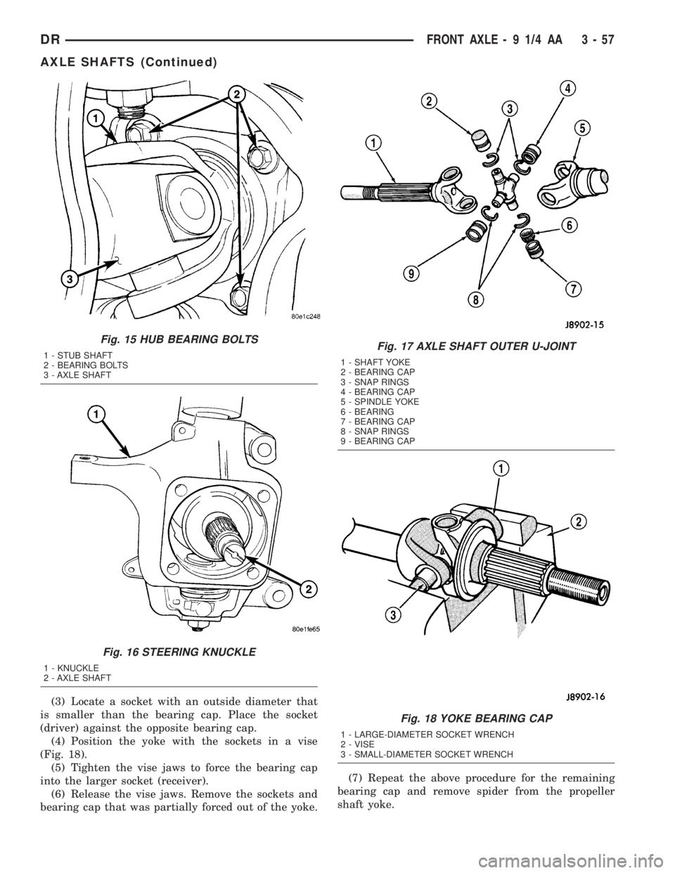
(4) Remove the four hub bearing bolts (Fig. 15)
from the back of the steering knuckle.
(5) Remove hub bearing from the steering knuckle.
(6) Remove axle shaft (Fig. 16) from steering
knuckle and axle housing.
DISASSEMBLY
Single cardan U-joint components are not service-
able. If defective they must be replaced as a unit.
CAUTION: Clamp only the narrow forged portion of
the yoke in the vise. To avoid distorting the yoke,
do not over tighten the vise jaws.
(1) Remove the bearing cap retaining snap rings
(Fig. 17).
NOTE: Saturate the bearing caps with penetrating
oil prior to removal.
(2) Locate a socket with an inside diameter that is
larger than the bearing cap. Place the socket (receiv-
er) against the yoke and around the perimeter of the
bearing cap to be removed.
ADAPTERS 8879
ADJUSTER WRENCH 8883
FLANGE WRENCH 8979
FLANGE PULLER 8992
Fig. 14 AXLE NUT
1 - AXLE NUT
2 - AXLE
3 - COTTER PIN
3 - 56 FRONT AXLE - 9 1/4 AADR
FRONT AXLE - 9 1/4 AA (Continued)
Page 130 of 2895

(3) Locate a socket with an outside diameter that
is smaller than the bearing cap. Place the socket
(driver) against the opposite bearing cap.
(4) Position the yoke with the sockets in a vise
(Fig. 18).
(5) Tighten the vise jaws to force the bearing cap
into the larger socket (receiver).
(6) Release the vise jaws. Remove the sockets and
bearing cap that was partially forced out of the yoke.(7) Repeat the above procedure for the remaining
bearing cap and remove spider from the propeller
shaft yoke.
Fig. 15 HUB BEARING BOLTS
1 - STUB SHAFT
2 - BEARING BOLTS
3 - AXLE SHAFT
Fig. 16 STEERING KNUCKLE
1 - KNUCKLE
2 - AXLE SHAFT
Fig. 17 AXLE SHAFT OUTER U-JOINT
1 - SHAFT YOKE
2 - BEARING CAP
3 - SNAP RINGS
4 - BEARING CAP
5 - SPINDLE YOKE
6 - BEARING
7 - BEARING CAP
8 - SNAP RINGS
9 - BEARING CAP
Fig. 18 YOKE BEARING CAP
1 - LARGE-DIAMETER SOCKET WRENCH
2 - VISE
3 - SMALL-DIAMETER SOCKET WRENCH
DRFRONT AXLE - 9 1/4 AA 3 - 57
AXLE SHAFTS (Continued)
Page 131 of 2895

ASSEMBLY
(1) Pack the bearing caps 1/3 full of wheel bearing
lubricant. Apply extreme pressure (EP), lithium-base
lubricant to aid in installation.
(2) Position the spider in the yoke. Insert the seals
and bearings. Tap the bearing caps into the yoke
bores far enough to hold the spider in position.
(3) Place the socket (driver) against one bearing
cap. Position the yoke with the socket in a vise.
(4) Tighten the vise to force the bearing caps into
the yoke. Force the caps enough to install the retain-
ing clips.
(5) Install the bearing cap retaining clips.
(6) Install axle shaft.
INSTALLATION
(1) Clean axle shaft and apply a thin film of
Mopar Wheel Bearing Grease to the shaft splines
and hub bore.
(2) Install axle shaft through the steering knuckle
and into the differential side gears (Fig. 19).
CAUTION: Do not damage axle shaft seal during
axle installtion.
(3) Install hub bearing in the knuckle.
(4) Install hub bearing bolts and tighten to 202
N´m (149 ft. lbs.).
(5) Install ABS wheel speed sensor, brake rotor
and caliper.
(6) Install axle washer and nut. Tighten axle nut
to 179 N´m (132 ft. lbs.).(7) Rotate axle several 5 to 10 times to seat the
wheel bearing.
(8) Tighten axle nut to final torque of 356 N´m
(263 ft. lbs.).
(9) Align nut to next cotter pin hole and install
new cotter pin.
(10) Install wheel and tire assembly.
AXLE SHAFT SEALS
REMOVAL
(1) Remove hub bearings and axle shafts.
(2) Remove differential from differential housing.
(3) Remove differential bearing adjusters (Fig. 20).
(4) Remove axle seals (Fig. 21) located behind
adjusters with Receiver 8498 and Extractor 6310.
(5) Install Receiver 8498 into the adjuster bore.
(6) Install Extractor Rod 6310 with Extractor Foot
6310-9 through the receiver and the axle seal (Fig.
22).
(7) Install Extractor Plate 6310-2 and Nut 6310-7
on the extractor rod.
(8) Tighten nut on the extractor rod (Fig. 23) and
pull the seal out and into the receiver.
INSTALLATION
(1) Install axle seal on Installer Cups 8885-2 and
position cups with seals into the housing.
NOTE: Seal are installed with the axle guide facing
outward.
Fig. 19 AXLE SHAFT
1 - AXLE YOKE
2 - AXLE SHAFT
3 - KNUCKLE
Fig. 20 ADJUSTERS
1 - DIFFERENTIAL CASE BEARING ADJUSTERS
2 - DIFFERENTIAL HOUSING
3 - 58 FRONT AXLE - 9 1/4 AADR
AXLE SHAFTS (Continued)
Page 229 of 2895

DIAGNOSIS AND TESTING - MASTER
CYLINDER/POWER BOOSTER...........20
STANDARD PROCEDURE - MASTER
CYLINDER BLEEDING..................20
REMOVAL
REMOVAL - ALL EXCEPT HYDROBOOST . . . 21
REMOVAL - HYDROBOOST.............21
INSTALLATION
INSTALLATION - ALL EXCEPT
HYDROBOOST.......................22
INSTALLATION - HYDROBOOST..........22
PEDAL
DESCRIPTION.........................22
OPERATION...........................22
REMOVAL.............................23
INSTALLATION.........................23
ADJUSTABLE PEDAL MOTOR
DESCRIPTION.........................24
REMOVAL.............................24
INSTALLATION.........................24
POWER BRAKE BOOSTER
DESCRIPTION.........................25
OPERATION...........................25
REMOVAL.............................25
INSTALLATION.........................25
HYDRO-BOOST BRAKE BOOSTER
DIAGNOSIS AND TESTING - HYDRAULIC
BOOSTER...........................25
STANDARD PROCEDURE - BLEEDING......27
REMOVAL.............................27
INSTALLATION.........................27
ROTORS
REMOVAL
REMOVAL - REAR.....................28
REMOVAL - FRONT....................28
INSTALLATION
INSTALLATION - REAR.................28
INSTALLATION - FRONT................29SUPPORT PLATE
REMOVAL.............................29
INSTALLATION.........................29
PARKING BRAKE
DESCRIPTION.........................30
OPERATION...........................30
CABLES
REMOVAL
REMOVAL - FRONT PARKING BRAKE
CABLE..............................31
REMOVAL - REAR PARK BRAKE CABLE . . . 31
REMOVAL - RIGHT REAR CABLE.........31
REMOVAL - LEFT REAR CABLE..........32
INSTALLATION
INSTALLATION - FRONT PARKING BRAKE
CABLE..............................32
INSTALLATION - REAR PARK BRAKE
CABLE..............................32
INSTALLATION - RIGHT REAR CABLE.....32
INSTALLATION - LEFT REAR CABLE......33
SHOES
REMOVAL.............................33
CLEANING - REAR DRUM IN HAT BRAKE....33
INSPECTION - REAR DRUM IN HAT BRAKE . . 33
INSTALLATION.........................34
ADJUSTMENTS
ADJUSTMENT - PARKING BRAKE SHOES . . 34
ADJUSTMENT - WITH ADJUSTING TOOL . . . 36
PEDAL
REMOVAL.............................36
INSTALLATION.........................36
CABLE TENSIONER
ADJUSTMENTS
ADJUSTMENT........................37
RELEASE HANDLE
REMOVAL.............................38
INSTALLATION.........................38
BRAKES - BASE
DIAGNOSIS AND TESTING - BASE BRAKE
SYSTEM
Base brake components consist of the brake shoes,
calipers, wheel cylinders, brake drums, rotors, brake
lines, master cylinder, booster, and parking brake
components.
Brake diagnosis involves determining if the prob-
lem is related to a mechanical, hydraulic, or vacuum
operated component.
The first diagnosis step is the preliminary check.
PRELIMINARY BRAKE CHECK
(1) Check condition of tires and wheels. Damaged
wheels and worn, damaged, or underinflated tires
can cause pull, shudder, vibration, and a condition
similar to grab.(2) If complaint was based on noise when braking,
check suspension components. Jounce front and rear
of vehicle and listen for noise that might be caused
by loose, worn or damaged suspension or steering
components.
(3) Inspect brake fluid level and condition. Note
that the brake reservoir fluid level will decrease in
proportion to normal lining wear.Also note that
brake fluid tends to darken over time. This is
normal and should not be mistaken for contam-
ination.
(a) If fluid level is abnormally low, look for evi-
dence of leaks at calipers, wheel cylinders, brake
lines, and master cylinder.
(b) If fluid appears contaminated, drain out a
sample to examine. System will have to be flushed
if fluid is separated into layers, or contains a sub-
stance other than brake fluid. The system seals
5 - 2 BRAKES - BASEDR
Page 231 of 2895

and resulting fade can also be caused by riding the
brake pedal, making repeated high deceleration stops
in a short time span, or constant braking on steep
mountain roads. Refer to the Brake Drag information
in this section for causes.
BRAKE PULL
Front brake pull condition could result from:
²Contaminated lining in one caliper
²Seized caliper piston
²Binding caliper
²Loose caliper
²Rusty caliper slide surfaces
²Improper brake shoes
²Damaged rotor
A worn, damaged wheel bearing or suspension
component are further causes of pull. A damaged
front tire (bruised, ply separation) can also cause
pull.
A common and frequently misdiagnosed pull condi-
tion is where direction of pull changes after a few
stops. The cause is a combination of brake drag fol-
lowed by fade at one of the brake units.
As the dragging brake overheats, efficiency is so
reduced that fade occurs. Since the opposite brake
unit is still functioning normally, its braking effect is
magnified. This causes pull to switch direction in
favor of the normally functioning brake unit.
An additional point when diagnosing a change in
pull condition concerns brake cool down. Remember
that pull will return to the original direction, if the
dragging brake unit is allowed to cool down (and is
not seriously damaged).
REAR BRAKE GRAB OR PULL
Rear grab or pull is usually caused by improperly
adjusted or seized parking brake cables, contami-
nated lining, bent or binding shoes and support
plates, or improperly assembled components. This is
particularly true when only one rear wheel is
involved. However, when both rear wheels are
affected, the master cylinder or proportioning valve
could be at fault.
BRAKES DO NOT HOLD AFTER DRIVING THROUGH DEEP
WATER PUDDLES
This condition is generally caused by water soaked
lining. If the lining is only wet, it can be dried by
driving with the brakes very lightly applied for a
mile or two. However, if the lining is both soaked and
dirt contaminated, cleaning and/or replacement will
be necessary.
BRAKE LINING CONTAMINATION
Brake lining contamination is mostly a product of
leaking calipers or wheel cylinders, worn seals, driv-
ing through deep water puddles, or lining that hasbecome covered with grease and grit during repair.
Contaminated lining should be replaced to avoid fur-
ther brake problems.
WHEEL AND TIRE PROBLEMS
Some conditions attributed to brake components
may actually be caused by a wheel or tire problem.
A damaged wheel can cause shudder, vibration and
pull. A worn or damaged tire can also cause pull.
Severely worn tires with very little tread left can
produce a grab-like condition as the tire loses and
recovers traction. Flat-spotted tires can cause vibra-
tion and generate shudder during brake operation. A
tire with internal damage such as a severe bruise,
cut, or ply separation can cause pull and vibration.
BRAKE NOISES
Some brake noise is common with rear drum
brakes and on some disc brakes during the first few
stops after a vehicle has been parked overnight or
stored. This is primarily due to the formation of trace
corrosion (light rust) on metal surfaces. This light
corrosion is typically cleared from the metal surfaces
after a few brake applications causing the noise to
subside.
BRAKE SQUEAK/SQUEAL
Brake squeak or squeal may be due to linings that
are wet or contaminated with brake fluid, grease, or
oil. Glazed linings and rotors with hard spots can
also contribute to squeak. Dirt and foreign material
embedded in the brake lining will also cause squeak/
squeal.
A very loud squeak or squeal is frequently a sign of
severely worn brake lining. If the lining has worn
through to the brake shoes in spots, metal-to-metal
contact occurs. If the condition is allowed to continue,
rotors and drums can become so scored that replace-
ment is necessary.
BRAKE CHATTER
Brake chatter is usually caused by loose or worn
components, or glazed/burnt lining. Rotors with hard
spots can also contribute to chatter. Additional causes
of chatter are out-of-tolerance rotors, brake lining not
securely attached to the shoes, loose wheel bearings
and contaminated brake lining.
THUMP/CLUNK NOISE
Thumping or clunk noises during braking are fre-
quentlynotcaused by brake components. In many
cases, such noises are caused by loose or damaged
steering, suspension, or engine components. However,
calipers that bind on the slide surfaces can generate
a thump or clunk noise. In addition, worn out,
improperly adjusted, or improperly assembled rear
brake shoes can also produce a thump noise.
5 - 4 BRAKES - BASEDR
BRAKES - BASE (Continued)
Page 237 of 2895

(3) Install the brake hose banjo bolt at the caliper
(Fig. 8).
(4) Reinstall the wheel speed sensor wire to the
brake hose (Fig. 8).
(5) Remove the support and lower the vehicle.
(6) Remove the prop rod from the brake pedal.
(7) Bleed the brake system (Refer to 5 - BRAKES -
STANDARD PROCEDURE).
BRAKE PADS/SHOES
REMOVAL
(1) Raise and support vehicle.
(2) Remove the wheel and tire assemblies.
(3) Compress the caliper.
(4) Remove the caliper, (Refer to 5 - BRAKES/HY-
DRAULIC/MECHANICAL/DISC BRAKE CALIPERS
- REMOVAL).
(5) Remove the caliper by tilting the top up and off
the caliper adapter (Fig. 10).
NOTE: Do not allow brake hose to support caliper
assembly.
(6) Support and hang the caliper. (Fig. 11)
(7) Remove the inboard brake shoe from the cali-
per adapter (Fig. 12).
(8) Remove the outboard brake shoe from the cali-
per adapter (Fig. 13).
(9) Remove the anti-rattle springs from the caliper
adapter (Fig. 14) and (Fig. 15).
NOTE: Anti-rattle springs are not interchangeable.
INSTALLATION
(1) Bottom pistons in caliper bore with C-clamp.
Place an old brake shoe between a C-clamp and cal-
iper piston.
(2) Clean caliper mounting adapter and anti-rattle
springs.
(3) Lubricate anti-rattle springs with Mopar brake
grease.
(4) Install anti-rattle springs.
NOTE: Anti-rattle springs are not interchangeable.
(5) Install inboard brake shoe in adapter.
Fig. 9 BRAKE HOSE MOUNT DRIVERS SIDE
1 - MOUNTING BOLT
2 - WHEEL SPEED SENSOR WIRE
3 - BRAKE HOSE
Fig. 10 Caliper
1 - CALIPER
2 - CALIPER ADAPTER
Fig. 11 DISC BRAKE CALIPER - FRONT
1 - STEERING KNUCKLE
2 - DISC BRAKE CALIPER
3 - CALIPER MOUNTING ADAPTER
4 - DISC BRAKE ROTOR
5 - 10 BRAKES - BASEDR
BRAKE LINES (Continued)
Page 240 of 2895

(2) Raise and support the vehicle.
(3) Remove the tire and wheel assembly.
(4) Compress the disc brake caliper.
(5) Remove the banjo bolt and discard the copper
washer.
(6) Remove the caliper slide pin bolts.
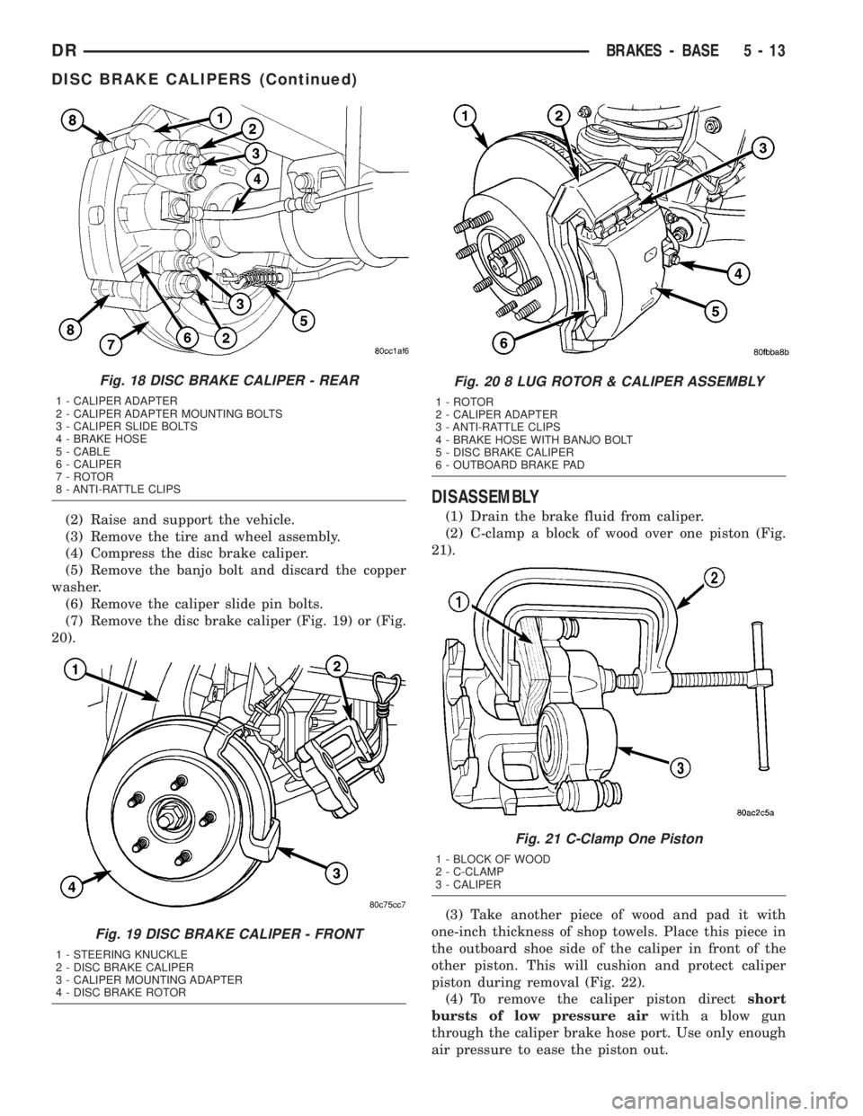
(7) Remove the disc brake caliper (Fig. 19) or (Fig.
20).
DISASSEMBLY
(1) Drain the brake fluid from caliper.
(2) C-clamp a block of wood over one piston (Fig.
21).
(3) Take another piece of wood and pad it with
one-inch thickness of shop towels. Place this piece in
the outboard shoe side of the caliper in front of the
other piston. This will cushion and protect caliper
piston during removal (Fig. 22).
(4) To remove the caliper piston directshort
bursts of low pressure airwith a blow gun
through the caliper brake hose port. Use only enough
air pressure to ease the piston out.
Fig. 18 DISC BRAKE CALIPER - REAR
1 - CALIPER ADAPTER
2 - CALIPER ADAPTER MOUNTING BOLTS
3 - CALIPER SLIDE BOLTS
4 - BRAKE HOSE
5 - CABLE
6 - CALIPER
7 - ROTOR
8 - ANTI-RATTLE CLIPS
Fig. 19 DISC BRAKE CALIPER - FRONT
1 - STEERING KNUCKLE
2 - DISC BRAKE CALIPER
3 - CALIPER MOUNTING ADAPTER
4 - DISC BRAKE ROTOR
Fig. 20 8 LUG ROTOR & CALIPER ASSEMBLY
1 - ROTOR
2 - CALIPER ADAPTER
3 - ANTI-RATTLE CLIPS
4 - BRAKE HOSE WITH BANJO BOLT
5 - DISC BRAKE CALIPER
6 - OUTBOARD BRAKE PAD
Fig. 21 C-Clamp One Piston
1 - BLOCK OF WOOD
2 - C-CLAMP
3 - CALIPER
DRBRAKES - BASE 5 - 13
DISC BRAKE CALIPERS (Continued)