2003 DODGE RAM low oil pressure
[x] Cancel search: low oil pressurePage 549 of 2895

(ISO) micro relay (Fig. 7). Relays conforming to the
ISO specifications have common physical dimensions,
current capacities, terminal patterns, and terminal
functions. The relay is contained within a small, rect-
angular, molded plastic housing and is connected to
all of the required inputs and outputs by five integral
male spade-type terminals that extend from the bot-
tom of the relay base.
The front fog lamp relay cannot be adjusted or
repaired and, if faulty or damaged, the unit must be
replaced.
OPERATION
The front fog lamp relay is an electromechanical
switch that uses a low current input from the Front
Control Module (FCM) to control a high current out-
put to the front fog lamps. The movable common feed
contact point is held against the fixed normally
closed contact point by spring pressure. When the
relay coil is energized, an electromagnetic field is
produced by the coil windings. This electromagnetic
field draws the movable relay contact point away
from the fixed normally closed contact point, and
holds it against the fixed normally open contact
point. When the relay coil is de-energized, spring
pressure returns the movable contact point back
against the fixed normally closed contact point. A
resistor is connected in parallel with the relay coil in
the relay, and helps to dissipate voltage spikes and
electromagnetic interference that can be generated as
the electromagnetic field of the relay coil collapses.
The front fog lamp relay terminals are connected
to the vehicle electrical system through a connector
receptacle in the Power Distribution Center (PDC).
The inputs and outputs of the front fog lamp relay
include:
²Common Feed Terminal- The common feed
terminal (30) receives battery voltage at all times
from a fuse in the PDC through a fused B(+) circuit.
²Coil Ground Terminal- The coil ground termi-
nal (85) is connected to a control output of the Front
Control Module (FCM) through a front fog lamp relay
control circuit. The FCM controls front fog lamp oper-
ation by controlling a ground path through this cir-
cuit.
²Coil Battery Terminal- The coil battery ter-
minal (86) receives battery voltage at all times from
a fuse in the PDC through a fused B(+) circuit.
²Normally Open Terminal- The normally open
terminal (87) is connected to the front fog lamps
through a front fog lamp relay output circuit and
provides battery voltage to the front fog lamps when-
ever the relay is energized.
²Normally Closed Terminal- The normally
closed terminal (87A) is not connected in this appli-
cation.The front fog lamp relay can be diagnosed using
conventional diagnostic tools and methods.
DIAGNOSIS AND TESTING - FRONT FOG LAMP
RELAY
The front fog lamp relay (Fig. 8) is located in the
Power Distribution Center in the engine compart-
ment. Refer to the appropriate wiring information.
WARNING: ON VEHICLES EQUIPPED WITH AIR-
BAGS, DISABLE THE SUPPLEMENTAL RESTRAINT
SYSTEM BEFORE ATTEMPTING ANY STEERING
WHEEL, STEERING COLUMN, DRIVER AIRBAG,
PASSENGER AIRBAG, SEAT BELT TENSIONER,
FRONT IMPACT SENSORS, SIDE CURTAIN AIRBAG,
OR INSTRUMENT PANEL COMPONENT DIAGNOSIS
OR SERVICE. DISCONNECT AND ISOLATE THE
BATTERY NEGATIVE (GROUND) CABLE, THEN
WAIT TWO MINUTES FOR THE SYSTEM CAPACI-
TOR TO DISCHARGE BEFORE PERFORMING FUR-
THER DIAGNOSIS OR SERVICE. THIS IS THE ONLY
SURE WAY TO DISABLE THE SUPPLEMENTAL
RESTRAINT SYSTEM. FAILURE TO TAKE THE
PROPER PRECAUTIONS COULD RESULT IN ACCI-
DENTAL AIRBAG DEPLOYMENT AND POSSIBLE
PERSONAL INJURY.
(1) Remove the front fog lamp relay from the PDC.
(Refer to 8 - ELECTRICAL/LAMPS/LIGHTING -
EXTERIOR/FRONT FOG LAMP RELAY - REMOV-
AL).
(2) A relay in the de-energized position should
have continuity between terminals 87A and 30, and
no continuity between terminals 87 and 30. If OK, go
to Step 3. If not OK, replace the faulty relay.
Fig. 8 ISO Micro Relay
30 - COMMON FEED
85 - COIL GROUND
86 - COIL BATTERY
87 - NORMALLY OPEN
87A - NORMALLY CLOSED
8L - 12 LAMPS/LIGHTING - EXTERIORDR
FOG LAMP RELAY (Continued)
Page 556 of 2895
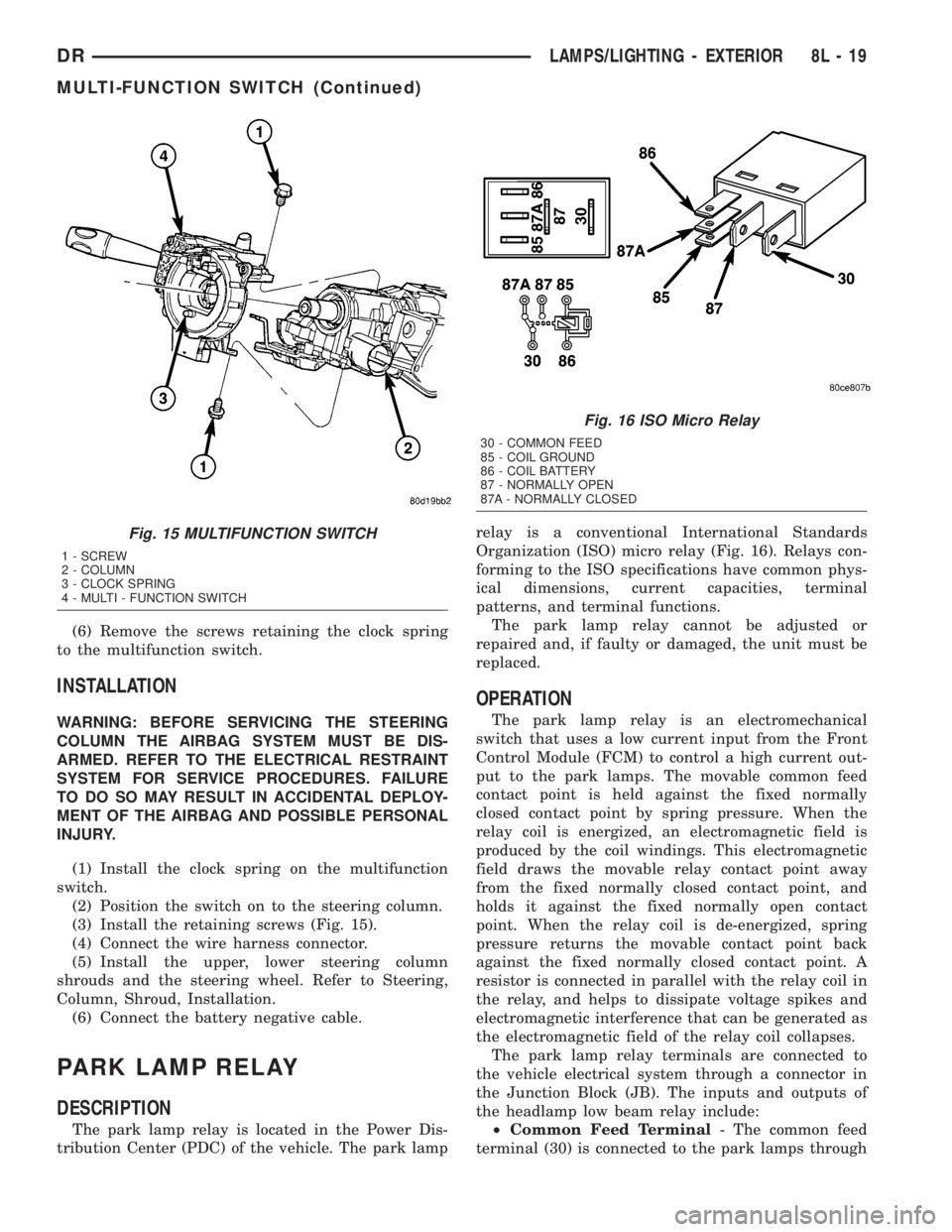
(6) Remove the screws retaining the clock spring
to the multifunction switch.
INSTALLATION
WARNING: BEFORE SERVICING THE STEERING
COLUMN THE AIRBAG SYSTEM MUST BE DIS-
ARMED. REFER TO THE ELECTRICAL RESTRAINT
SYSTEM FOR SERVICE PROCEDURES. FAILURE
TO DO SO MAY RESULT IN ACCIDENTAL DEPLOY-
MENT OF THE AIRBAG AND POSSIBLE PERSONAL
INJURY.
(1) Install the clock spring on the multifunction
switch.
(2) Position the switch on to the steering column.
(3) Install the retaining screws (Fig. 15).
(4) Connect the wire harness connector.
(5) Install the upper, lower steering column
shrouds and the steering wheel. Refer to Steering,
Column, Shroud, Installation.
(6) Connect the battery negative cable.
PARK LAMP RELAY
DESCRIPTION
The park lamp relay is located in the Power Dis-
tribution Center (PDC) of the vehicle. The park lamprelay is a conventional International Standards
Organization (ISO) micro relay (Fig. 16). Relays con-
forming to the ISO specifications have common phys-
ical dimensions, current capacities, terminal
patterns, and terminal functions.
The park lamp relay cannot be adjusted or
repaired and, if faulty or damaged, the unit must be
replaced.
OPERATION
The park lamp relay is an electromechanical
switch that uses a low current input from the Front
Control Module (FCM) to control a high current out-
put to the park lamps. The movable common feed
contact point is held against the fixed normally
closed contact point by spring pressure. When the
relay coil is energized, an electromagnetic field is
produced by the coil windings. This electromagnetic
field draws the movable relay contact point away
from the fixed normally closed contact point, and
holds it against the fixed normally open contact
point. When the relay coil is de-energized, spring
pressure returns the movable contact point back
against the fixed normally closed contact point. A
resistor is connected in parallel with the relay coil in
the relay, and helps to dissipate voltage spikes and
electromagnetic interference that can be generated as
the electromagnetic field of the relay coil collapses.
The park lamp relay terminals are connected to
the vehicle electrical system through a connector in
the Junction Block (JB). The inputs and outputs of
the headlamp low beam relay include:
²Common Feed Terminal- The common feed
terminal (30) is connected to the park lamps through
Fig. 15 MULTIFUNCTION SWITCH
1 - SCREW
2 - COLUMN
3 - CLOCK SPRING
4 - MULTI - FUNCTION SWITCH
Fig. 16 ISO Micro Relay
30 - COMMON FEED
85 - COIL GROUND
86 - COIL BATTERY
87 - NORMALLY OPEN
87A - NORMALLY CLOSED
DRLAMPS/LIGHTING - EXTERIOR 8L - 19
MULTI-FUNCTION SWITCH (Continued)
Page 695 of 2895
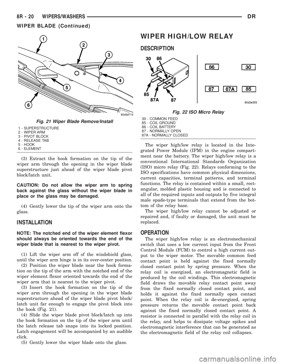
(3) Extract the hook formation on the tip of the
wiper arm through the opening in the wiper blade
superstructure just ahead of the wiper blade pivot
block/latch unit.
CAUTION: Do not allow the wiper arm to spring
back against the glass without the wiper blade in
place or the glass may be damaged.
(4) Gently lower the tip of the wiper arm onto the
glass.
INSTALLATION
NOTE: The notched end of the wiper element flexor
should always be oriented towards the end of the
wiper blade that is nearest to the wiper pivot.
(1)
Lift the wiper arm off of the windshield glass,
until the wiper arm hinge is in its over-center position.
(2) Position the wiper blade near the hook forma-
tion on the tip of the arm with the notched end of the
wiper element flexor oriented towards the end of the
wiper arm that is nearest to the wiper pivot.
(3) Insert the hook formation on the tip of the
wiper arm through the opening in the wiper blade
superstructure ahead of the wiper blade pivot block/
latch unit far enough to engage the pivot block into
the hook (Fig. 21).
(4) Slide the wiper blade pivot block/latch up into
the hook formation on the tip of the wiper arm until
the latch release tab snaps into its locked position.
Latch engagement will be accompanied by an audible
click.
(5) Gently lower the wiper blade onto the glass.
WIPER HIGH/LOW RELAY
DESCRIPTION
The wiper high/low relay is located in the Inte-
grated Power Module (IPM) in the engine compart-
ment near the battery. The wiper high/low relay is a
conventional International Standards Organization
(ISO) micro relay (Fig. 22). Relays conforming to the
ISO specifications have common physical dimensions,
current capacities, terminal patterns, and terminal
functions. The relay is contained within a small, rect-
angular, molded plastic housing and is connected to
all of the required inputs and outputs by five integral
male spade-type terminals that extend from the bot-
tom of the relay base.
The wiper high/low relay cannot be adjusted or
repaired and, if faulty or damaged, the unit must be
replaced.
OPERATION
The wiper high/low relay is an electromechanical
switch that uses a low current input from the Front
Control Module (FCM) to control a high current out-
put to the wiper motor. The movable common feed
contact point is held against the fixed normally
closed contact point by spring pressure. When the
relay coil is energized, an electromagnetic field is
produced by the coil windings. This electromagnetic
field draws the movable relay contact point away
from the fixed normally closed contact point, and
holds it against the fixed normally open contact
point. When the relay coil is de-energized, spring
pressure returns the movable contact point back
against the fixed normally closed contact point. A
resistor is connected in parallel with the relay coil in
the relay, and helps to dissipate voltage spikes and
electromagnetic interference that can be generated as
the electromagnetic field of the relay coil collapses.
Fig. 21 Wiper Blade Remove/Install
1 - SUPERSTRUCTURE
2 - WIPER ARM
3 - PIVOT BLOCK
4 - RELEASE TAB
5 - HOOK
6 - ELEMENT
Fig. 22 ISO Micro Relay
30 - COMMON FEED
85 - COIL GROUND
86 - COIL BATTERY
87 - NORMALLY OPEN
87A - NORMALLY CLOSED
8R - 20 WIPERS/WASHERSDR
WIPER BLADE (Continued)
Page 700 of 2895
WIPER ON/OFF RELAY
DESCRIPTION
The wiper on/off relay is located in the Integrated
Power Module (IPM) in the engine compartment near
the battery. The wiper on/off relay is a conventional
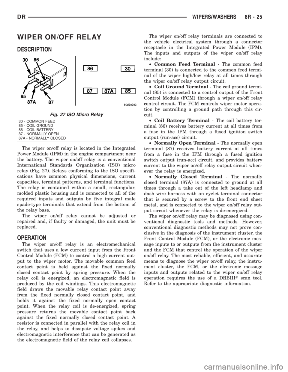
International Standards Organization (ISO) micro
relay (Fig. 27). Relays conforming to the ISO specifi-
cations have common physical dimensions, current
capacities, terminal patterns, and terminal functions.
The relay is contained within a small, rectangular,
molded plastic housing and is connected to all of the
required inputs and outputs by five integral male
spade-type terminals that extend from the bottom of
the relay base.
The wiper on/off relay cannot be adjusted or
repaired and, if faulty or damaged, the unit must be
replaced.
OPERATION
The wiper on/off relay is an electromechanical
switch that uses a low current input from the Front
Control Module (FCM) to control a high current out-
put to the wiper motor. The movable common feed
contact point is held against the fixed normally
closed contact point by spring pressure. When the
relay coil is energized, an electromagnetic field is
produced by the coil windings. This electromagnetic
field draws the movable relay contact point away
from the fixed normally closed contact point, and
holds it against the fixed normally open contact
point. When the relay coil is de-energized, spring
pressure returns the movable contact point back
against the fixed normally closed contact point. A
resistor is connected in parallel with the relay coil in
the relay, and helps to dissipate voltage spikes and
electromagnetic interference that can be generated as
the electromagnetic field of the relay coil collapses.The wiper on/off relay terminals are connected to
the vehicle electrical system through a connector
receptacle in the Integrated Power Module (IPM).
The inputs and outputs of the wiper on/off relay
include:
²Common Feed Terminal- The common feed
terminal (30) is connected to the common feed termi-
nal of the wiper high/low relay at all times through
the wiper on/off relay output circuit.
²Coil Ground Terminal- The coil ground termi-
nal (85) is connected to a control output of the Front
Control Module (FCM) through a wiper on/off relay
control circuit. The FCM controls wiper motor opera-
tion by controlling a ground path through this cir-
cuit.
²Coil Battery Terminal- The coil battery ter-
minal (86) receives battery current at all times from
a fuse in the IPM through a fused ignition switch
output (run-acc) circuit.
²Normally Open Terminal- The normally open
terminal (87) receives battery current at all times
from a fuse in the IPM through a fused ignition
switch output (run-acc) circuit, and provides battery
current to the wiper on/off relay output circuit when-
ever the relay is energized.
²Normally Closed Terminal- The normally
closed terminal (87A) is connected to ground at all
times through a take out of the left headlamp and
dash wire harness with an eyelet terminal connector
that is secured by a screw to the front end sheet
metal, and is connected to the wiper on/off relay out-
put circuit whenever the relay is de-energized.
The wiper on/off relay may be diagnosed using con-
ventional diagnostic tools and methods. However,
conventional diagnostic methods may not prove con-
clusive in the diagnosis of the instrument cluster, the
Front Control Module (FCM), or the electronic mes-
sage inputs to or outputs from the instrument cluster
and the FCM that control the operation of the wiper
on/off relay. The most reliable, efficient, and accurate
means to diagnose the wiper on/off relay, the instru-
ment cluster, the FCM, or the electronic message
inputs and outputs related to the wiper on/off relay
operation requires the use of a DRBIIItscan tool.
Refer to the appropriate diagnostic information.
Fig. 27 ISO Micro Relay
30 - COMMON FEED
85 - COIL GROUND
86 - COIL BATTERY
87 - NORMALLY OPEN
87A - NORMALLY CLOSED
DRWIPERS/WASHERS 8R - 25
Page 720 of 2895

8W-02 COMPONENT INDEX
Component Page
4WD Switch......................... 8W-30
A/C Compressor Clutch Relay............ 8W-42
A/C Compressor Clutch................. 8W-42
A/C Pressure Transducer................ 8W-42
A/C-Heater Control.................... 8W-42
Accelerator Pedal Position Sensor......... 8W-30
Adjustable Pedal Motor................. 8W-30
Adjustable Pedal Relay................. 8W-30
Adjustable Pedal Switch................ 8W-30
Airbag Control Modules................ 8W-43
Airbags............................. 8W-43
Ambient Temperature Sensor............ 8W-49
Amplifier Audio....................... 8W-47
Auto Shut Down Relay................. 8W-30
Automatic Day/Night Mirror............. 8W-49
Auxiliary Battery..................... 8W-20
Backup Lamp Switch.................. 8W-51
Battery Temperature Sensor............. 8W-30
Battery............................. 8W-20
Blend Door Actuator................... 8W-42
Blower Motor Resistor Block............. 8W-42
Blower Motor......................... 8W-42
Brake Lamp Switch.................... 8W-33
Brake Transmission Shift Interlock
Solenoid........................... 8W-40
Camshaft Position Sensor............... 8W-30
Capacitor............................ 8W-30
Center High Mounted Stop Lamp/Cargo
Lamp.......................... 8W-44, 51
Center High Mounted Stop Lamp-
Aftermarket..................... 8W-33, 51
Cigar Lighter Outlet................... 8W-41
Circuit Breaker....................... 8W-10
Clearance Lamps...................... 8W-50
Clockspring................. 8W-33, 41, 43, 47
Clutch Interlock Brake Switch........... 8W-21
Coil On Plugs........................ 8W-30
Compass/Mini-Trip Computer............ 8W-49
Condenser Fan Relay.................. 8W-42
Condenser Fan....................... 8W-42
Controller Antilock Brake............ 8W-34, 35
Crankshaft Position Sensor.............. 8W-30
Cylinder Lock Switch-Driver............. 8W-61
Cylinder Lock Switch-Passenger.......... 8W-61
Data Link Connector................... 8W-18
Data Link Connector-Engine............. 8W-18
Dome Lamp.......................... 8W-44
Door Ajar Switches.................... 8W-40
Door Lock Motor/Ajar Switches........ 8W-40, 61
Door Lock Switch-Passenger............. 8W-61
Driver Door Module.............. 8W-60, 61, 62
Electric Brake Provision............. 8W-33, 54Component Page
Electronic Throttle Control Module........ 8W-30
Engine Control Module................. 8W-30
Engine Coolant Temperature Sensor....... 8W-30
Engine Oil Pressure Switch.............. 8W-30
EVAP/Purge Solenoid.................. 8W-30
Evaporator Temperature Sensor.......... 8W-42
Fender Lamps........................ 8W-51
Fog Lamp Relay...................... 8W-50
Fog Lamps.......................... 8W-50
Front Control Module.................. 8W-10
Fuel Heater Relay..................... 8W-30
Fuel Heater.......................... 8W-30
Fuel Injectors........................ 8W-30
Fuel Injector Packs.................... 8W-30
Fuel Pump Module.................... 8W-30
Fuel Pump Motor..................... 8W-30
Fuel Pump Relay...................... 8W-30
Fuel Rail Pressure Sensor............... 8W-30
Fuses............................... 8W-10
Fusible Link......................... 8W-10
Grounds............................ 8W-15
Generator........................... 8W-20
Glove Box Lamp And Switch............. 8W-44
Headlamp Switch.................. 8W-40, 50
Headlamps.......................... 8W-50
Heated Mirror Relay................... 8W-62
Heated Seat Cushions.................. 8W-63
Heated Seat Switches.................. 8W-63
Horn Relay.......................... 8W-41
Horn Switch......................... 8W-41
Horns.............................. 8W-41
Idle Air Control Motor............ 8W-30, 30-36
Ignition Coils......................... 8W-30
Ignition Switch....................... 8W-10
Inlet Air Temperature/Pressure Sensor..... 8W-30
Input Speed Sensor.................... 8W-31
Instrument Cluster.................... 8W-40
Intake Air Heater Relays............... 8W-30
Intake Air Temperature Sensor........... 8W-30
Intake Air Temperature/Manifold Absolute
Pressure Sensor..................... 8W-30
Integrated Power Module............... 8W-10
Knock Sensors........................ 8W-30
Leak Detection Pump.................. 8W-30
License Lamps....................... 8W-51
Lift Pump Motor...................... 8W-30
Line Pressure Sensor................ 8W-30, 31
Lumbar Motors....................... 8W-63
Manifold Absolute Pressure Sensor........ 8W-30
Mode Door Actuators................... 8W-42
Multi-Function Switch............ 8W-40, 52, 53
Output Speed Sensor................... 8W-31
DR8W-02 COMPONENT INDEX 8W - 02 - 1
Page 1070 of 2895
Component Page
Glove Box Lamp And Switch.......... 8W-80-63
Headlamp Switch................... 8W-80-63
Headlamp-Left..................... 8W-80-64
Headlamp-Right.................... 8W-80-64
Heated Seat Cushion-Passenger........ 8W-80-64
Heated Seat Switch-Driver............ 8W-80-64
Heated Seat Switch-Passenger......... 8W-80-65
Horn Switch....................... 8W-80-65
Horn-High Note.................... 8W-80-65
Horn-Low Note..................... 8W-80-65
Idle Air Control Motor (3.7L/5.9L/8.0L) . . 8W-80-65
Idle Air Control Motor (NGC).......... 8W-80-66
Ignition Coil (5.9L).................. 8W-80-66
Ignition Coil-Left (8.0L).............. 8W-80-66
Ignition Coil-Right (8.0L)............. 8W-80-66
Ignition Switch..................... 8W-80-67
Inlet Air Temperature/ Pressure Sensor
(Diesel)......................... 8W-80-67
Input Speed Sensor (3.7L/4.7L/5.7L)..... 8W-80-67
Instrument Cluster C1............... 8W-80-68
Instrument Cluster C2............... 8W-80-68
Instrument Cluster C3............... 8W-80-69
Intake Air Temperature Sensor........ 8W-80-69
Intake Air Temperature/Manifold Absolute
Pressure Sensor (Diesel)............ 8W-80-69
Integrated Power Module C1.......... 8W-80-70
Integrated Power Module C2.......... 8W-80-70
Integrated Power Module C3.......... 8W-80-71
Integrated Power Module C4.......... 8W-80-71
Integrated Power Module C5.......... 8W-80-72
Integrated Power Module C6.......... 8W-80-72
Integrated Power Module C7.......... 8W-80-73
Knock Sensor (3.7L)................. 8W-80-73
Knock Sensor-Left (5.7L)............. 8W-80-74
Knock Sensor-Right (5.7L)............ 8W-80-74
Leak Detection Pump (NGC).......... 8W-80-74
Leak Detection Pump................ 8W-80-74
License Lamp-Left.................. 8W-80-74
License Lamp-Right................. 8W-80-75
Lift Pump Motor (Diesel)............. 8W-80-75
Line Pressure Sensor (3.7L/5.7L)....... 8W-80-75
Line Pressure Sensor (4.7L)........... 8W-80-75
Lumbar Motor-Driver................ 8W-80-76
Lumbar Motor-Passenger............. 8W-80-76
Manifold Absolute Pressure Sensor
(3.7L/4.7L/5.7L).................. 8W-80-76
Manifold Absolute Pressure Sensor
(5.9L/8.0L)...................... 8W-80-76
Mode Door Actuator 1 (Panel To Floor) . . . 8W-80-77
Mode Door Actuator 2 (Defrost To Floor) . 8W-80-77
Multi-Function Switch............... 8W-80-77
Output Speed Sensor (3.7L/4.7L/5.7L) . . . 8W-80-77
Output Speed Sensor (5.9L)........... 8W-80-77
Output Speed Sensor (Diesel).......... 8W-80-78Component Page
Overdrive Switch................... 8W-80-78
Overhead Map/Reading Lamp (Except
Base).......................... 8W-80-78
Oxygen Sensor 1/1 Upstream.......... 8W-80-78
Oxygen Sensor 1/2 Downstream........ 8W-80-79
Oxygen Sensor 2/1 Upstream (California 4.7L/
California 5.9L).................. 8W-80-79
Oxygen Sensor 2/2 Downstream (California
4.7L/California 5.9L)............... 8W-80-79
Park/Turn Signal Lamp-Left Front...... 8W-80-80
Park/Turn Signal Lamp-Right Front.... 8W-80-80
Passenger Blend Door Actuator (Dual-
Zone).......................... 8W-80-80
Passenger Lumbar Switch............ 8W-80-80
Power Mirror-Left................... 8W-80-80
Power Mirror-Right................. 8W-80-81
Power Outlet...................... 8W-80-81
Power Outlet-Console (Except Base)..... 8W-80-81
Power Seat Motor-Driver Front Vertical . . 8W-80-81
Power Seat Motor-Driver Horizontal.... 8W-80-82
Power Seat Motor-Driver Rear Vertical . . 8W-80-82
Power Seat Switch-Driver............ 8W-80-82
Power Seat Switch-Passenger.......... 8W-80-82
Power Steering Pressure Switch
(3.7L/4.7L/5.7L).................. 8W-80-83
Power Window Motor-Driver.......... 8W-80-83
Power Window Motor-Left Rear........ 8W-80-83
Power Window Motor-Passenger........ 8W-80-83
Power Window Motor-Right Rear....... 8W-80-83
Power Window Switch-Left Rear....... 8W-80-84
Power Window Switch-Right Rear...... 8W-80-84
Power Window-Circuit Breaker........ 8W-80-84
Powertrain Control Module........... 8W-80-84
Powertrain Control Module........... 8W-80-85
Powertrain Control Module........... 8W-80-86
Powertrain Control Module C1 (JTEC) . . . 8W-80-87
Powertrain Control Module C1 (NGC) . . . 8W-80-88
Powertrain Control Module C2 (JTEC) . . . 8W-80-89
Powertrain Control Module C2 (NGC) . . . 8W-80-90
Powertrain Control Module C3 (JTEC) . . . 8W-80-91
Powertrain Control Module C3 (NGC) . . . 8W-80-92
Powertrain Control Module C4 (NGC) . . . 8W-80-93
Radio (Base)....................... 8W-80-94
Radio (Premium)................... 8W-80-94
Recirculation Door Actuator........... 8W-80-95
Remote Radio Switch-Left............ 8W-80-95
Remote Radio Switch-Right........... 8W-80-95
Seat Heater Interface Module.......... 8W-80-95
Sentry Key Immobilizer Module........ 8W-80-96
Speaker-Center Instrument Panel...... 8W-80-96
Speaker-Left Front Door.............. 8W-80-96
Speaker-Left Instrument Panel........ 8W-80-96
Speaker-Left Rear.................. 8W-80-96
Speaker-Right Front Door............ 8W-80-97
DR8W-80 CONNECTOR PIN-OUTS 8W - 80 - 3
Page 1122 of 2895
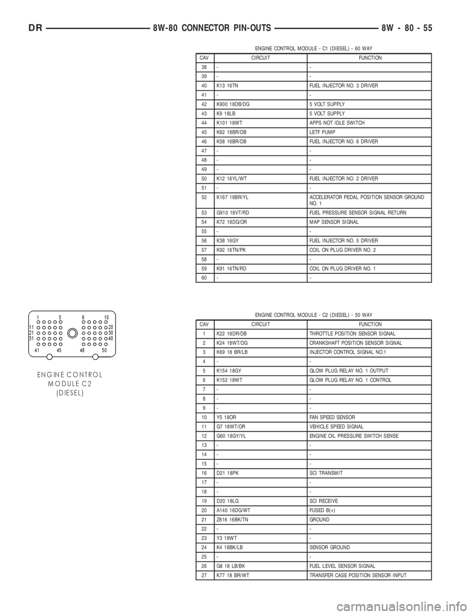
ENGINE CONTROL MODULE - C1 (DIESEL) - 60 WAY
CAV CIRCUIT FUNCTION
38 - -
39 - -
40 K13 16TN FUEL INJECTOR NO. 3 DRIVER
41 - -
42 K900 18DB/DG 5 VOLT SUPPLY
43 K9 18LB 5 VOLT SUPPLY
44 K101 18WT APPS NOT IDLE SWITCH
45 K62 18BR/DB LETF PUMP
46 K58 16BR/DB FUEL INJECTOR NO. 6 DRIVER
47 - -
48 - -
49 - -
50 K12 16YL/WT FUEL INJECTOR NO. 2 DRIVER
51 - -
52 K167 18BR/YL ACCELERATOR PEDAL POSITION SENSOR GROUND
NO. 1
53 G910 18VT/RD FUEL PRESSURE SENSOR SIGNAL RETURN
54 K72 18DG/OR MAP SENSOR SIGNAL
55 - -
56 K38 16GY FUEL INJECTOR NO. 5 DRIVER
57 K92 16TN/PK COIL ON PLUG DRIVER NO. 2
58 - -
59 K91 16TN/RD COIL ON PLUG DRIVER NO. 1
60 - -
ENGINE CONTROL MODULE - C2 (DIESEL) - 50 WAY
CAV CIRCUIT FUNCTION
1 K22 18DR/DB THROTTLE POSITION SENSOR SIGNAL
2 K24 18WT/DG CRANKSHAFT POSITION SENSOR SIGNAL
3 K69 18 BR/LB INJECTOR CONTROL SIGNAL NO.1
4- -
5 K154 18GY GLOW PLUG RELAY NO. 1 OUTPUT
6 K152 18WT GLOW PLUG RELAY NO. 1 CONTROL
7- -
8- -
9- -
10 Y5 18OR FAN SPEED SENSOR
11 G7 18WT/OR VEHICLE SPEED SIGNAL
12 G60 18GY/YL ENGINE OIL PRESSURE SWITCH SENSE
13 - -
14 - -
15 - -
16 D21 18PK SCI TRANSMIT
17 - -
18 - -
19 D20 18LG SCI RECEIVE
20 A140 16DG/WT FUSED B(+)
21 Z816 16BK/TN GROUND
22 - -
23 Y3 18WT -
24 K4 18BK/LB SENSOR GROUND
25 - -
26 G8 18 LB/BK FUEL LEVEL SENSOR SIGNAL
27 K77 18 BR/WT TRANSFER CASE POSITION SENSOR INPUT
DR8W-80 CONNECTOR PIN-OUTS 8W - 80 - 55
Page 1181 of 2895
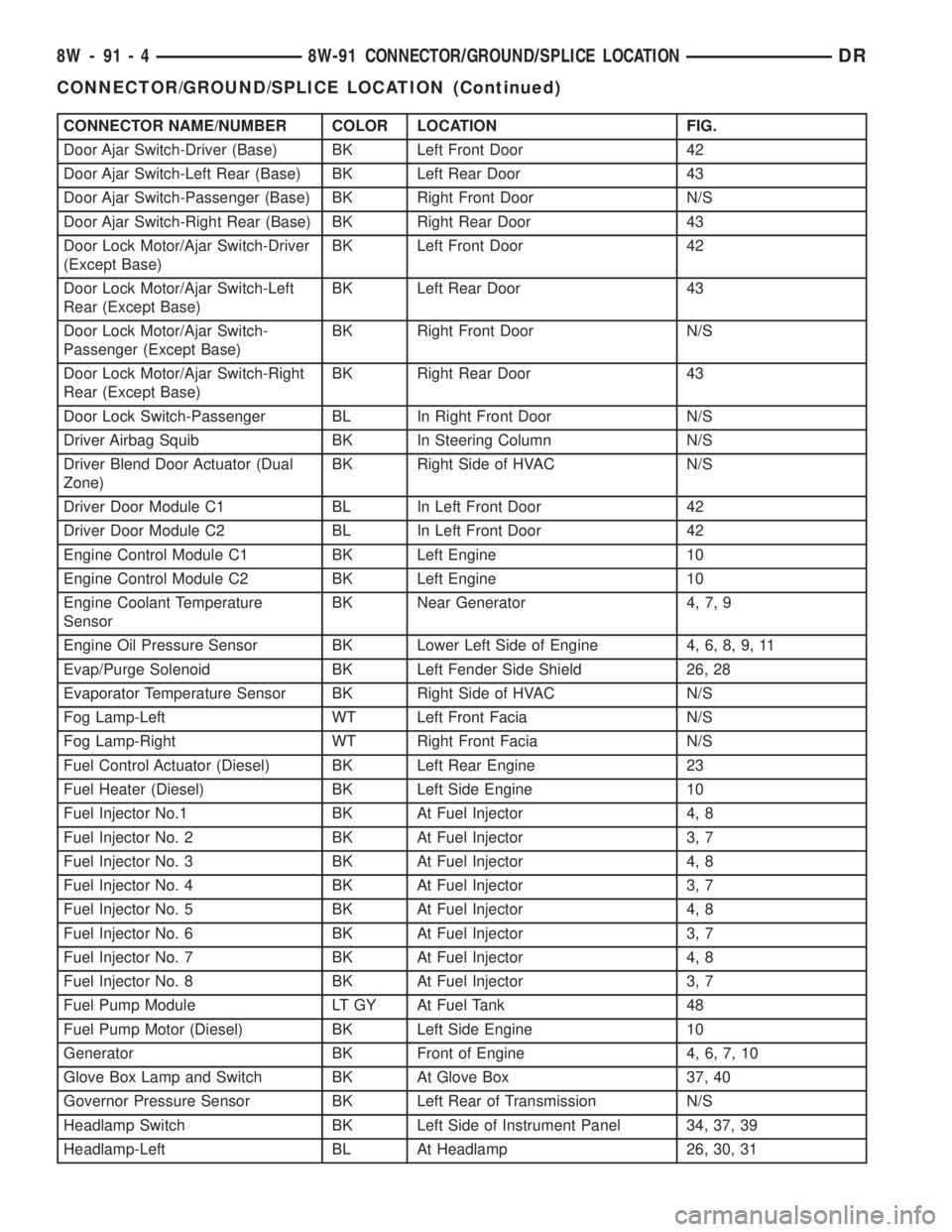
CONNECTOR NAME/NUMBER COLOR LOCATION FIG.
Door Ajar Switch-Driver (Base) BK Left Front Door 42
Door Ajar Switch-Left Rear (Base) BK Left Rear Door 43
Door Ajar Switch-Passenger (Base) BK Right Front Door N/S
Door Ajar Switch-Right Rear (Base) BK Right Rear Door 43
Door Lock Motor/Ajar Switch-Driver
(Except Base)BK Left Front Door 42
Door Lock Motor/Ajar Switch-Left
Rear (Except Base)BK Left Rear Door 43
Door Lock Motor/Ajar Switch-
Passenger (Except Base)BK Right Front Door N/S
Door Lock Motor/Ajar Switch-Right
Rear (Except Base)BK Right Rear Door 43
Door Lock Switch-Passenger BL In Right Front Door N/S
Driver Airbag Squib BK In Steering Column N/S
Driver Blend Door Actuator (Dual
Zone)BK Right Side of HVAC N/S
Driver Door Module C1 BL In Left Front Door 42
Driver Door Module C2 BL In Left Front Door 42
Engine Control Module C1 BK Left Engine 10
Engine Control Module C2 BK Left Engine 10
Engine Coolant Temperature
SensorBK Near Generator 4, 7, 9
Engine Oil Pressure Sensor BK Lower Left Side of Engine 4, 6, 8, 9, 11
Evap/Purge Solenoid BK Left Fender Side Shield 26, 28
Evaporator Temperature Sensor BK Right Side of HVAC N/S
Fog Lamp-Left WT Left Front Facia N/S
Fog Lamp-Right WT Right Front Facia N/S
Fuel Control Actuator (Diesel) BK Left Rear Engine 23
Fuel Heater (Diesel) BK Left Side Engine 10
Fuel Injector No.1 BK At Fuel Injector 4, 8
Fuel Injector No. 2 BK At Fuel Injector 3, 7
Fuel Injector No. 3 BK At Fuel Injector 4, 8
Fuel Injector No. 4 BK At Fuel Injector 3, 7
Fuel Injector No. 5 BK At Fuel Injector 4, 8
Fuel Injector No. 6 BK At Fuel Injector 3, 7
Fuel Injector No. 7 BK At Fuel Injector 4, 8
Fuel Injector No. 8 BK At Fuel Injector 3, 7
Fuel Pump Module LT GY At Fuel Tank 48
Fuel Pump Motor (Diesel) BK Left Side Engine 10
Generator BK Front of Engine 4, 6, 7, 10
Glove Box Lamp and Switch BK At Glove Box 37, 40
Governor Pressure Sensor BK Left Rear of Transmission N/S
Headlamp Switch BK Left Side of Instrument Panel 34, 37, 39
Headlamp-Left BL At Headlamp 26, 30, 31
8W - 91 - 4 8W-91 CONNECTOR/GROUND/SPLICE LOCATIONDR
CONNECTOR/GROUND/SPLICE LOCATION (Continued)