2003 DODGE RAM Fig 25 INSTRUMENT PANEL
[x] Cancel search: Fig 25 INSTRUMENT PANELPage 499 of 2895

ule must be replaced. The cluster lens, hood and
mask unit and the individual incandescent lamp
bulbs with holders are available for individual ser-
vice replacement.
OPERATION
The ElectroMechanical Instrument Cluster (EMIC)
in this model also includes the hardware and soft-
ware necessary to serve as the electronic body control
module and is sometimes referred to as the Cab
Compartment Node or CCN. The following informa-
tion deals primarily with the instrument cluster
functions of this unit. Additional details of the elec-
tronic body control functions of this unit may be
found within the service information for the system
or component that the EMIC controls. For example:
Additional details of the audible warning functions of
the EMIC are found within the Chime/Buzzer service
information.The EMIC is designed to allow the vehicle operator
to monitor the conditions of many of the vehicle com-
ponents and operating systems. The gauges and indi-
cators in the EMIC provide valuable information
about the various standard and optional powertrains,
fuel and emissions systems, cooling systems, lighting
systems, safety systems and many other convenience
items. The EMIC is installed in the instrument panel
so that all of these monitors can be easily viewed by
the vehicle operator when driving, while still allow-
ing relative ease of access for service. The micropro-
cessor-based EMIC hardware and software uses
various inputs to control the gauges and indicators
visible on the face of the cluster. Some of these
inputs are hard wired, but most are in the form of
electronic messages that are transmitted by other
electronic modules over the Programmable Communi-
cations Interface (PCI) data bus network. (Refer to 8
- ELECTRICAL/ELECTRONIC CONTROL MOD-
ULES/COMMUNICATION - OPERATION).
Fig. 3 Gauges & Indicators - Gasoline Engine
1 - MALFUNCTION INDICATOR LAMP 13 - ELECTRONIC THROTTLE CONTROL (ETC) INDICATOR
2 - VOLTAGE GAUGE 14 - ENGINE TEMPERATURE GAUGE
3 - LEFT TURN INDICATOR 15 - SECURITY INDICATOR
4 - TACHOMETER 16 - GEAR SELECTOR INDICATOR DISPLAY (INCLUDES
CRUISE & UPSHIFT INDICATORS)
5 - AIRBAG INDICATOR 17 - CHECK GAUGES INDICATOR
6 - HIGH BEAM INDICATOR 18 - BRAKE INDICATOR
7 - SEATBELT INDICATOR 19 - ABS INDICATOR
8 - SPEEDOMETER 20 - ODOMETER/TRIP ODOMETER DISPLAY (INCLUDES
ENGINE HOURS, WASHER FLUID, LAMP OUTAGE,
OVERDRIVE-OFF & SERVICE 4x4 INDICATORS)
9 - RIGHT TURN INDICATOR 21 - ODOMETER/TRIP ODOMETER SWITCH BUTTON
10 - OIL PRESSURE GAUGE 22 - FUEL GAUGE
11 - CARGO LAMP INDICATOR 23 - LOW FUEL INDICATOR
12 - DOOR AJAR INDICATOR 24 - TRANSMISSION OVERTEMP INDICATOR
8J - 6 INSTRUMENT CLUSTERDR
INSTRUMENT CLUSTER (Continued)
Page 500 of 2895
The EMIC microprocessor smooths the input data
using algorithms to provide gauge readings that are
accurate, stable and responsive to operating condi-
tions. These algorithms are designed to provide
gauge readings during normal operation that are con-
sistent with customer expectations. However, when
abnormal conditions exist such as high coolant tem-
perature, the algorithm can drive the gauge pointer
to an extreme position and the microprocessor can
sound a chime through the on-board audible tone
generator to provide distinct visual and audible indi-
cations of a problem to the vehicle operator. The
instrument cluster circuitry may also produce audi-
ble warnings for other electronic modules in the vehi-
cle based upon electronic tone request messages
received over the PCI data bus. Each audible warn-
ing is intended to provide the vehicle operator with
an audible alert to supplement a visual indication.The EMIC circuitry operates on battery current
received through a fused B(+) fuse in the Integrated
Power Module (IPM) on a non-switched fused B(+)
circuit, and on battery current received through a
fused ignition switch output (run-start) fuse in the
IPM on a fused ignition switch output (run-start) cir-
cuit. This arrangement allows the EMIC to provide
some features regardless of the ignition switch posi-
tion, while other features will operate only with the
ignition switch in the On or Start positions. The
EMIC circuitry is grounded through a ground circuit
and take out of the instrument panel wire harness
with an eyelet terminal connector that is secured by
a ground screw to a ground location near the center
of the instrument panel structural support.
The EMIC also has a self-diagnostic actuator test
capability, which will test each of the PCI bus mes-
sage-controlled functions of the cluster by lighting
the appropriate indicators, positioning the gauge nee-
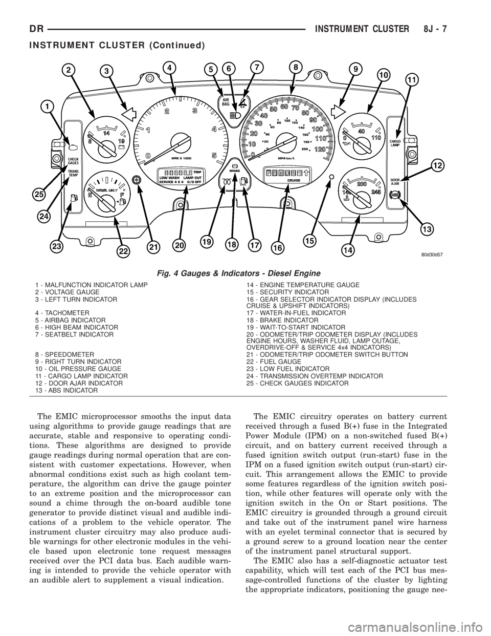
Fig. 4 Gauges & Indicators - Diesel Engine
1 - MALFUNCTION INDICATOR LAMP 14 - ENGINE TEMPERATURE GAUGE
2 - VOLTAGE GAUGE 15 - SECURITY INDICATOR
3 - LEFT TURN INDICATOR 16 - GEAR SELECTOR INDICATOR DISPLAY (INCLUDES
CRUISE & UPSHIFT INDICATORS)
4 - TACHOMETER 17 - WATER-IN-FUEL INDICATOR
5 - AIRBAG INDICATOR 18 - BRAKE INDICATOR
6 - HIGH BEAM INDICATOR 19 - WAIT-TO-START INDICATOR
7 - SEATBELT INDICATOR 20 - ODOMETER/TRIP ODOMETER DISPLAY (INCLUDES
ENGINE HOURS, WASHER FLUID, LAMP OUTAGE,
OVERDRIVE-OFF & SERVICE 4x4 INDICATORS)
8 - SPEEDOMETER 21 - ODOMETER/TRIP ODOMETER SWITCH BUTTON
9 - RIGHT TURN INDICATOR 22 - FUEL GAUGE
10 - OIL PRESSURE GAUGE 23 - LOW FUEL INDICATOR
11 - CARGO LAMP INDICATOR 24 - TRANSMISSION OVERTEMP INDICATOR
12 - DOOR AJAR INDICATOR 25 - CHECK GAUGES INDICATOR
13 - ABS INDICATOR
DRINSTRUMENT CLUSTER 8J - 7
INSTRUMENT CLUSTER (Continued)
Page 502 of 2895

ajar indicator, high beam indicator, and turn signal
indicators operate based upon hard wired inputs to
the EMIC. The brake indicator is controlled by PCI
data bus messages from the Controller Antilock
Brake (CAB) as well as by hard wired park brake
switch inputs to the EMIC. The seatbelt indicator is
controlled by the EMIC programming, PCI data bus
messages from the Airbag Control Module (ACM),
and a hard wired seat belt switch input to the EMIC.
The Malfunction Indicator Lamp (MIL) is normally
controlled by PCI data bus messages from the Pow-
ertrain Control Module (PCM); however, if the EMIC
loses PCI data bus communication, the EMIC cir-
cuitry will automatically turn the MIL on until PCI
data bus communication is restored. The EMIC uses
PCI data bus messages from the Front Control Mod-
ule (FCM), the PCM, the diesel engine only Engine
Control Module (ECM), the ACM, the CAB, and the
Sentry Key Immobilizer Module (SKIM) to control all
of the remaining indicators.
The various EMIC indicators are controlled by dif-
ferent strategies; some receive fused ignition switch
output from the EMIC circuitry and have a switched
ground, while others are grounded through the EMIC
circuitry and have a switched battery feed. However,
all indicators are completely controlled by the EMIC
microprocessor based upon various hard wired and
electronic message inputs. All indicators are illumi-
nated at a fixed intensity, which is not affected by
the selected illumination intensity of the EMIC gen-
eral illumination lamps.
In addition, certain indicators in this instrument
cluster are automatically configured or self-config-
ured. This feature allows the configurable indicators
to be enabled by the EMIC circuitry for compatibility
with certain optional equipment. The EMIC defaults
for the ABS indicator and airbag indicator are
enabled, and these configuration settings must be
programmatically disabled in the EMIC using a
DRBIIItscan tool for vehicles that do not have this
equipment. The automatically configured or self-con-
figured indicators remain latent in each EMIC at all
times and will be active only when the EMIC
receives the appropriate PCI message inputs for that
optional system or equipment.
The hard wired indicator inputs may be diagnosed
using conventional diagnostic methods. However, the
EMIC circuitry and PCI bus message controlled indi-
cators are diagnosed using the EMIC self-diagnostic
actuator test. (Refer to 8 - ELECTRICAL/INSTRU-
MENT CLUSTER - DIAGNOSIS AND TESTING).
Proper testing of the PCI data bus and the electronic
message inputs to the EMIC that control an indicator
requires the use of a DRBIIItscan tool. Refer to the
appropriate diagnostic information. Specific details ofthe operation for each indicator may be found else-
where in this service information.
CLUSTER ILLUMINATION
The EMIC has several illumination lamps that are
illuminated when the exterior lighting is turned on
with the headlamp switch. The illumination intensity
of these lamps is adjusted when the interior lighting
thumbwheel on the headlamp switch is rotated (down
to dim, up to brighten) to one of six available minor
detent positions. The EMIC monitors a resistor mul-
tiplexed input from the headlamp switch on a dim-
mer input circuit. In response to that input, the
EMIC electronic circuitry converts a 12-volt input it
receives from a fuse in the Integrated Power Module
(IPM) on a hard wired panel lamps dimmer switch
signal circuit into a 12-volt Pulse Width Modulated
(PWM) output. The EMIC uses this PWM output to
power the cluster illumination lamps and the VFD
units on the EMIC circuit board, then provides a syn-
chronized PWM output on the various hard wired
fused panel lamps dimmer switch signal circuits to
control and synchronize the illumination intensity of
other incandescent illumination lamps in the vehicle.
The cluster illumination lamps are grounded at all
times.
The EMIC also sends electronic dimming level
messages over the PCI data bus to other electronic
modules in the vehicle to control and synchronize the
illumination intensity of their VFD units to that of
the EMIC VFD units. In addition, the thumbwheel
on the headlamp switch has a Parade Mode position
to provide a parade mode. The EMIC monitors the
request for this mode from the headlamp switch,
then sends an electronic dimming level message over
the PCI data bus to illuminate all VFD units in the
vehicle at full (daytime) intensity for easier visibility
when driving in daylight with the exterior lighting
turned on.
The hard wired headlamp switch and EMIC panel
lamps dimmer inputs and outputs may be diagnosed
using conventional diagnostic methods. However,
proper testing of the PWM output of the EMIC and
the electronic dimming level messages sent by the
EMIC over the PCI data bus requires the use of a
DRBIIItscan tool. Refer to the appropriate diagnos-
tic information.
INPUT AND OUTPUT CIRCUITS
HARD WIRED INPUTS
The hard wired inputs to the EMIC include the fol-
lowing:
²Brake Lamp Switch Output
²Driver Cylinder Lock Switch Sense
²Driver Door Ajar Switch Sense
DRINSTRUMENT CLUSTER 8J - 9
INSTRUMENT CLUSTER (Continued)
Page 504 of 2895

CAUTION: Instrument clusters used in this model
automatically configure themselves for compatibil-
ity with the features and optional equipment in the
vehicle in which they are initially installed. The
instrument cluster is programmed to do this by
embedding the Vehicle Identification Number (VIN)
and other information critical to proper cluster
operation into electronic memory. This embedded
information is learned through electronic messages
received from other electronic modules in the vehi-
cle over the Programmable Communications Inter-
face (PCI) data bus, and through certain hard wired
inputs received when the cluster is connected to
the vehicle electrically. Once configured, the instru-
ment cluster memory may be irreparably damaged
and certain irreversible configuration errors may
occur if the cluster is connected electrically to
another vehicle; or, if an electronic module from
another vehicle is connected that provides data to
the instrument cluster (including odometer values)
that conflicts with that which was previously
learned and stored. Therefore, the practice of
exchanging (swapping) instrument clusters and
other electronic modules in this vehicle with those
removed from another vehicle must always be
avoided. Failure to observe this caution may result
in instrument cluster damage, which is not reim-
bursable under the terms of the product warranty.
Service replacement instrument clusters are pro-
vided with the correct VIN, and the certified odom-
eter and engine hours values embedded into cluster
memory, but will otherwise be automatically config-
ured for compatibility with the features and optional
equipment in the vehicle in which they are initially
installed.
NOTE: Certain indicators in this instrument cluster
are automatically configured. This feature allows
those indicators to be activated or deactivated for
compatibility with certain optional equipment. If the
problem being diagnosed involves improper illumi-
nation of the cruise indicator, the electronic throttle
control indicator, the overdrive-off indicator, the
service four-wheel drive indicator, the transmission
overtemp indicator, the upshift indicator, the secu-
rity indicator or the gear selector indicator, discon-
nect and isolate the battery negative cable. After
about five minutes, reconnect the battery negative
cable and turn the ignition switch to the On posi-
tion. The instrument cluster should automatically
relearn the equipment in the vehicle and properly
configure the configurable indicators accordingly.PRELIMINARY DIAGNOSIS
WARNING: ON VEHICLES EQUIPPED WITH AIR-
BAGS, DISABLE THE SUPPLEMENTAL RESTRAINT
SYSTEM BEFORE ATTEMPTING ANY STEERING
WHEEL, STEERING COLUMN, DRIVER AIRBAG,
PASSENGER AIRBAG, SEAT BELT TENSIONER,
SIDE CURTAIN AIRBAG, OR INSTRUMENT PANEL
COMPONENT DIAGNOSIS OR SERVICE. DISCON-
NECT AND ISOLATE THE BATTERY NEGATIVE
(GROUND) CABLE, THEN WAIT TWO MINUTES FOR
THE SYSTEM CAPACITOR TO DISCHARGE BEFORE
PERFORMING FURTHER DIAGNOSIS OR SERVICE.
THIS IS THE ONLY SURE WAY TO DISABLE THE
SUPPLEMENTAL RESTRAINT SYSTEM. FAILURE TO
TAKE THE PROPER PRECAUTIONS COULD
RESULT IN ACCIDENTAL AIRBAG DEPLOYMENT
AND POSSIBLE PERSONAL INJURY.
(1) Check the fused B(+) fuse (Fuse 28 - 10
ampere) in the Integrated Power Module (IPM). If
OK, go to Step 2. If not OK, repair the shorted circuit
or component as required and replace the faulty fuse.
(2) Check for battery voltage at the fused B(+) fuse
(Fuse 28 - 10 ampere) in the IPM. If OK, go to Step
3. If not OK, repair the open fused B(+) circuit
between the IPM and the battery as required.
(3) Disconnect and isolate the battery negative
cable. Remove the instrument cluster. Reconnect the
battery negative cable. Check for battery voltage at
the fused B(+) circuit cavity of the instrument panel
wire harness connector (Connector C1) for the instru-
ment cluster. If OK, go to Step 4. If not OK, repair
the open fused B(+) circuit between the instrument
cluster and the IPM as required.
(4) Check for continuity between the signal ground
circuit cavity of the instrument panel wire harness
connector (Connector C1) for the instrument cluster
and a good ground. There should be continuity. If
OK, refer to ACTUATOR TEST. If not OK, repair the
open ground circuit to ground (G202) as required.
DRINSTRUMENT CLUSTER 8J - 11
INSTRUMENT CLUSTER (Continued)
Page 507 of 2895
INSTRUMENT CLUSTER FAILURE MESSAGE
Fault Code Description Correction
AD FCM messages not received. Refer to the appropriate diagnostic information.
AE ACM messages not received. Refer to the appropriate diagnostic information.
AF SKIM messages not received. Refer to the appropriate diagnostic information.
B0 RKE fob batteries low. Refer to the appropriate diagnostic information.
B1 RKE module communication link. Refer to the appropriate diagnostic information.
00 Done All Diagnostic Trouble Codes (DTC) have been
displayed.
(7) The actuator test is now completed. The instru-
ment cluster will automatically exit the self-diagnos-
tic mode and return to normal operation at the
completion of the test, if the ignition switch is turned
to the Off position during the test, or if a vehicle
speed message indicating that the vehicle is moving
is received from the PCM over the PCI data bus dur-
ing the test.
(8)
Go back to Step 1 to repeat the test, if necessary.
REMOVAL
WARNING: ON VEHICLES EQUIPPED WITH AIR-
BAGS, DISABLE THE SUPPLEMENTAL RESTRAINT
SYSTEM BEFORE ATTEMPTING ANY STEERING
WHEEL, STEERING COLUMN, DRIVER AIRBAG,
PASSENGER AIRBAG, SEAT BELT TENSIONER,
SIDE CURTAIN AIRBAG, OR INSTRUMENT PANEL
COMPONENT DIAGNOSIS OR SERVICE. DISCON-
NECT AND ISOLATE THE BATTERY NEGATIVE
(GROUND) CABLE, THEN WAIT TWO MINUTES FOR
THE SYSTEM CAPACITOR TO DISCHARGE BEFORE
PERFORMING FURTHER DIAGNOSIS OR SERVICE.
THIS IS THE ONLY SURE WAY TO DISABLE THE
SUPPLEMENTAL RESTRAINT SYSTEM. FAILURE TO
TAKE THE PROPER PRECAUTIONS COULD
RESULT IN ACCIDENTAL AIRBAG DEPLOYMENT
AND POSSIBLE PERSONAL INJURY.
(1) Disconnect and isolate the battery negative
cable.
(2) Remove the cluster bezel from the instrument
panel. (Refer to 23 - BODY/INSTRUMENT PANEL/
CLUSTER BEZEL - REMOVAL).
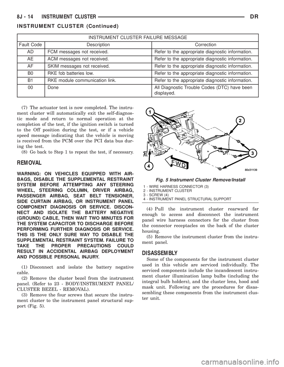
(3) Remove the four screws that secure the instru-
ment cluster to the instrument panel structural sup-
port (Fig. 5).(4) Pull the instrument cluster rearward far
enough to access and disconnect the instrument
panel wire harness connectors for the cluster from
the connector receptacles on the back of the cluster
housing.
(5) Remove the instrument cluster from the instru-
ment panel.
DISASSEMBLY
Some of the components for the instrument cluster
used in this vehicle are serviced individually. The
serviced components include the incandescent instru-
ment cluster illumination lamp bulbs (including the
integral bulb holders), and the cluster lens, hood and
mask unit. Following are the procedures for disas-
sembling these components from the instrument clus-
ter unit.
Fig. 5 Instrument Cluster Remove/Install
1 - WIRE HARNESS CONNECTOR (3)
2 - INSTRUMENT CLUSTER
3 - SCREW (4)
4 - INSTRUMENT PANEL STRUCTURAL SUPPORT
8J - 14 INSTRUMENT CLUSTERDR
INSTRUMENT CLUSTER (Continued)
Page 508 of 2895
WARNING: ON VEHICLES EQUIPPED WITH AIR-
BAGS, DISABLE THE SUPPLEMENTAL RESTRAINT
SYSTEM BEFORE ATTEMPTING ANY STEERING
WHEEL, STEERING COLUMN, DRIVER AIRBAG,
PASSENGER AIRBAG, SEAT BELT TENSIONER,
SIDE CURTAIN AIRBAG, OR INSTRUMENT PANEL
COMPONENT DIAGNOSIS OR SERVICE. DISCON-
NECT AND ISOLATE THE BATTERY NEGATIVE
(GROUND) CABLE, THEN WAIT TWO MINUTES FOR
THE SYSTEM CAPACITOR TO DISCHARGE BEFORE
PERFORMING FURTHER DIAGNOSIS OR SERVICE.
THIS IS THE ONLY SURE WAY TO DISABLE THE
SUPPLEMENTAL RESTRAINT SYSTEM. FAILURE TO
TAKE THE PROPER PRECAUTIONS COULD
RESULT IN ACCIDENTAL AIRBAG DEPLOYMENT
AND POSSIBLE PERSONAL INJURY.
CLUSTER BULB
This procedure applies to each of the incandescent
cluster illumination lamp bulb and bulb holder units.
If the vehicle is equipped with the optional Remote
Keyless Entry (RKE) system, the RKE receiver mod-
ule must be removed from the instrument cluster
rear cover to access the lower center cluster illumi-
nation lamp, which is located on the circuit board
directly behind the RKE module. (Refer to 8 - ELEC-
TRICAL/POWER LOCKS/REMOTE KEYLESS
ENTRY MODULE - REMOVAL).
(1) Disconnect and isolate the battery negative
cable.
(2) Remove the instrument cluster from the instru-
ment panel. (Refer to 8 - ELECTRICAL/INSTRU-
MENT CLUSTER - REMOVAL).
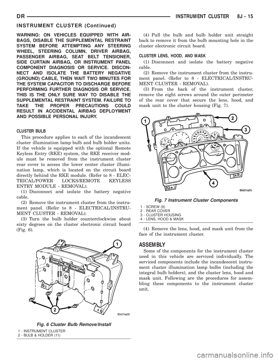
(3) Turn the bulb holder counterclockwise about
sixty degrees on the cluster electronic circuit board
(Fig. 6).(4) Pull the bulb and bulb holder unit straight
back to remove it from the bulb mounting hole in the
cluster electronic circuit board.
CLUSTER LENS, HOOD, AND MASK
(1) Disconnect and isolate the battery negative
cable.
(2) Remove the instrument cluster from the instru-
ment panel. (Refer to 8 - ELECTRICAL/INSTRU-
MENT CLUSTER - REMOVAL).
(3) From the back of the instrument cluster,
remove the eight screws around the outer perimeter
of the rear cover that secure the lens, hood, and
mask unit to the cluster housing (Fig. 7).
(4) Remove the lens, hood, and mask unit from the
face of the instrument cluster.
ASSEMBLY
Some of the components for the instrument cluster
used in this vehicle are serviced individually. The
serviced components include the incandescent instru-
ment cluster illumination lamp bulbs (including the
integral bulb holders), and the cluster lens, hood and
mask unit. Following are the procedures for assem-
bling these components to the instrument cluster
unit.
Fig. 6 Cluster Bulb Remove/Install
1 - INSTRUMENT CLUSTER
2 - BULB & HOLDER (11)
Fig. 7 Instrument Cluster Components
1 - SCREW (9)
2 - REAR COVER
3 - CLUSTER HOUSING
4 - LENS, HOOD & MASK
DRINSTRUMENT CLUSTER 8J - 15
INSTRUMENT CLUSTER (Continued)
Page 509 of 2895
WARNING: ON VEHICLES EQUIPPED WITH AIR-
BAGS, DISABLE THE SUPPLEMENTAL RESTRAINT
SYSTEM BEFORE ATTEMPTING ANY STEERING
WHEEL, STEERING COLUMN, DRIVER AIRBAG,
PASSENGER AIRBAG, SEAT BELT TENSIONER,
SIDE CURTAIN AIRBAG, OR INSTRUMENT PANEL
COMPONENT DIAGNOSIS OR SERVICE. DISCON-
NECT AND ISOLATE THE BATTERY NEGATIVE
(GROUND) CABLE, THEN WAIT TWO MINUTES FOR
THE SYSTEM CAPACITOR TO DISCHARGE BEFORE
PERFORMING FURTHER DIAGNOSIS OR SERVICE.
THIS IS THE ONLY SURE WAY TO DISABLE THE
SUPPLEMENTAL RESTRAINT SYSTEM. FAILURE TO
TAKE THE PROPER PRECAUTIONS COULD
RESULT IN ACCIDENTAL AIRBAG DEPLOYMENT
AND POSSIBLE PERSONAL INJURY.
CLUSTER BULB
This procedure applies to each of the incandescent
cluster illumination lamp bulb and bulb holder units.
If the vehicle is equipped with the optional Remote
Keyless Entry (RKE) system, and the RKE receiver
module was removed from the instrument cluster
rear cover to access the lower center cluster illumi-
nation lamp, reinstall the RKE module after the bulb
is replaced on the circuit board. (Refer to 8 - ELEC-
TRICAL/POWER LOCKS/REMOTE KEYLESS
ENTRY MODULE - INSTALLATION).
CAUTION: Always use the correct bulb size and
type for replacement. An incorrect bulb size or type
may overheat and cause damage to the instrument
cluster, the electronic circuit board and/or the
gauges.
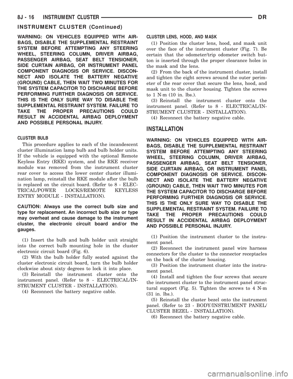
(1) Insert the bulb and bulb holder unit straight
into the correct bulb mounting hole in the cluster
electronic circuit board (Fig. 6).
(2) With the bulb holder fully seated against the
cluster electronic circuit board, turn the bulb holder
clockwise about sixty degrees to lock it into place.
(3) Reinstall the instrument cluster onto the
instrument panel. (Refer to 8 - ELECTRICAL/IN-
STRUMENT CLUSTER - INSTALLATION).
(4) Reconnect the battery negative cable.CLUSTER LENS, HOOD, AND MASK
(1) Position the cluster lens, hood, and mask unit
over the face of the instrument cluster (Fig. 7). Be
certain that the odometer/trip odometer switch but-
ton is inserted through the proper clearance holes in
the mask and the lens.
(2) From the back of the instrument cluster, install
and tighten the eight screws around the outer perim-
eter of the rear cover that secure the lens, hood, and
mask unit to the cluster housing. Tighten the screws
to 1 N´m (10 in. lbs.).
(3) Reinstall the instrument cluster onto the
instrument panel. (Refer to 8 - ELECTRICAL/IN-
STRUMENT CLUSTER - INSTALLATION).
(4) Reconnect the battery negative cable.
INSTALLATION
WARNING: ON VEHICLES EQUIPPED WITH AIR-
BAGS, DISABLE THE SUPPLEMENTAL RESTRAINT
SYSTEM BEFORE ATTEMPTING ANY STEERING
WHEEL, STEERING COLUMN, DRIVER AIRBAG,
PASSENGER AIRBAG, SEAT BELT TENSIONER,
SIDE CURTAIN AIRBAG, OR INSTRUMENT PANEL
COMPONENT DIAGNOSIS OR SERVICE. DISCON-
NECT AND ISOLATE THE BATTERY NEGATIVE
(GROUND) CABLE, THEN WAIT TWO MINUTES FOR
THE SYSTEM CAPACITOR TO DISCHARGE BEFORE
PERFORMING FURTHER DIAGNOSIS OR SERVICE.
THIS IS THE ONLY SURE WAY TO DISABLE THE
SUPPLEMENTAL RESTRAINT SYSTEM. FAILURE TO
TAKE THE PROPER PRECAUTIONS COULD
RESULT IN ACCIDENTAL AIRBAG DEPLOYMENT
AND POSSIBLE PERSONAL INJURY.
(1) Position the instrument cluster to the instru-
ment panel.
(2) Reconnect the instrument panel wire harness
connectors for the cluster to the connector receptacles
on the back of the cluster housing.
(3) Position the instrument cluster into the instru-
ment panel.
(4) Install and tighten the four screws that secure
the instrument cluster to the instrument panel struc-
tural support (Fig. 5). Tighten the screws to 4 N´m
(31 in. lbs.).
(5) Reinstall the cluster bezel onto the instrument
panel. (Refer to 23 - BODY/INSTRUMENT PANEL/
CLUSTER BEZEL - INSTALLATION).
(6) Reconnect the battery negative cable.
8J - 16 INSTRUMENT CLUSTERDR
INSTRUMENT CLUSTER (Continued)
Page 520 of 2895

The gear selector indicator displays the following
characters from left to right: ªP,º ªR,º ªN,º ªD,º ª2,º
and ª1.º Respectively, these characters represent the
park, reverse, neutral, drive, second gear, and first
gear positions of the transmission gear selector lever
on the steering column. The VFD illuminates a rect-
angular box around the character that represents the
currently selected lever position.
The gear selector indicator characters and graphics
appear in the same blue-green color and at the same
lighting level as the odometer/trip odometer informa-
tion when illuminated by the instrument cluster elec-
tronic circuit board. During daylight hours (exterior
lamps Off) the gear selector indicator VFD is illumi-
nated at full brightness for clear visibility. At night
(exterior lamps are On) the VFD lighting level is
adjusted with the other cluster illumination lamps
using the panel lamps dimmer thumbwheel on the
headlamp switch. However, a ªParadeº mode position
of the panel lamps dimmer thumbwheel allows the
VFD to be illuminated at full brightness when the
vehicle is driven in daylight hours with the exterior
lamps turned On. The gear selector indicator VFD is
serviced as a unit with the instrument cluster.
OPERATION
The electronic gear selector indicator gives an indi-
cation to the vehicle operator of the transmission
gear that has been selected with the automatic trans-
mission gear selector lever. This indicator is con-
trolled by the instrument cluster circuit board based
upon cluster programming. The cluster circuitry
automatically configures itself for the proper trans-
mission and automatic transmission model based
upon the hard wired transmission range sensor mux
circuit input to the cluster. The gear selector indica-
tor information is displayed by a dedicated Vacuum
Fluorescent Display (VFD) unit on the instrument
cluster electronic circuit board, and the VFD will not
display the gear selector indicator information after
the ignition switch is turned to the Off position. The
instrument cluster circuitry configures the gear selec-
tor indicator VFD based upon the following inputs
from the transmission range sensor:
²Open Circuit- If the cluster is configured for
an automatic transmission and the transmission
range sensor mux circuit is open, the cluster circuitry
controls the gear selector indicator display based
upon electronic messages received from the electronic
Transmission Control Module (TCM) over the Pro-
grammable Communications Interface (PCI) data
bus. If the transmission range sensor mux circuit is
open and no electronic messages are received from
the TCM within two seconds, the instrument cluster
circuitry will not display any gear selector position
until the condition is resolved or until the ignitionswitch is turned to the Off position, whichever occurs
first.
²Resolved Circuit- If the transmission range
sensor mux circuit is resolved, the cluster circuitry
controls the gear selector indicator display based
upon the resistance value of the hard wired input
from the transmission range sensor. If the cluster is
configured for an automatic transmission with a
transmission range sensor input and detects a short
to ground or an open in the transmission range sen-
sor mux input, the instrument cluster circuitry will
not display any gear selector position in the VFD.
The VFD display for the short-to-ground and open
circuit conditions will continue until the condition is
resolved or until the ignition switch is turned to the
Off position, whichever occurs first.
²Actuator Test- Each time the cluster is put
through the actuator test, the gear selector indicator
VFD will display all of its characters at once during
the VFD portion of the test to confirm the function-
ality of the VFD and the cluster control circuitry.
On models with a TCM, the TCM continually mon-
itors the transmission range sensor, then sends the
proper gear selector indicator position messages to
the instrument cluster. On models without a TCM,
the instrument cluster continually monitors the hard
wired transmission range sensor multiplexed input.
For further diagnosis of the gear selector indicator or
the instrument cluster circuitry that controls this
function, (Refer to 8 - ELECTRICAL/INSTRUMENT
CLUSTER - DIAGNOSIS AND TESTING). For fur-
ther diagnosis of the transmission range sensor on
models without a TCM, (Refer to 21 - TRANSMIS-
SION/TRANSAXLE/AUTOMATIC - 42RE/TRANS-
MISSION RANGE SENSOR - DIAGNOSIS AND
TESTING) or (Refer to 21 - TRANSMISSION/
TRANSAXLE/AUTOMATIC - 46RE/TRANSMISSION
RANGE SENSOR - DIAGNOSIS AND TESTING).
On models with a TCM, for proper diagnosis of the
transmission range sensor, the TCM, the PCI data
bus, or the electronic message inputs to the instru-
ment cluster that control the gear selector indicator,
a DRBIIItscan tool is required. Refer to the appro-
priate diagnostic information.
HIGH BEAM INDICATOR
DESCRIPTION
A high beam indicator is standard equipment on
all instrument clusters. The high beam indicator is
located near the upper edge of the instrument clus-
ter, between the tachometer and the speedometer.
The high beam indicator consists of a stencil-like cut-
out of the International Control and Display Symbol
icon for ªHigh Beamº in the opaque layer of the
DRINSTRUMENT CLUSTER 8J - 27
GEAR SELECTOR INDICATOR (Continued)