2003 DODGE RAM Fig 25 INSTRUMENT PANEL
[x] Cancel search: Fig 25 INSTRUMENT PANELPage 2801 of 2895
DIAGNOSIS AND TESTING - BLOWER MOTOR
WARNING: ON VEHICLES EQUIPPED WITH AIR-
BAGS, DISABLE THE AIRBAG SYSTEM BEFORE
ATTEMPTING ANY STEERING WHEEL, STEERING
COLUMN, OR INSTRUMENT PANEL COMPONENT
DIAGNOSIS OR SERVICE. DISCONNECT AND ISO-
LATE THE BATTERY NEGATIVE (GROUND) CABLE,
THEN WAIT TWO MINUTES FOR THE AIRBAG SYS-
TEM CAPACITOR TO DISCHARGE BEFORE PER-
FORMING FURTHER DIAGNOSIS OR SERVICE. THIS
IS THE ONLY SURE WAY TO DISABLE THE AIRBAG
SYSTEM. FAILURE TO TAKE THE PROPER PRE-
CAUTIONS COULD RESULT IN AN ACCIDENTAL
AIRBAG DEPLOYMENT AND POSSIBLE PERSONAL
INJURY.
For circuit descriptions and diagrams, (Refer to
Appropriate Wiring Information). Possible causes of
an inoperative blower motor include:
²Faulty fuse
²Faulty blower motor circuit wiring or wire har-
ness connectors
²Faulty blower motor resistor
²Faulty blower motor relay
²Faulty blower motor switch
²Faulty A/C Heater mode control switch
²Faulty blower motor.
Possible causes of the blower motor not operating
in all speeds include:
²Faulty blower motor switch
²Faulty blower motor resistor
²Faulty blower motor circuit wiring or wire har-
ness connectors.
VIBRATION
Possible causes of blower motor vibration include:
²Improper blower motor mounting
²Improper blower wheel mounting
²Blower wheel out of balance or bent
²Blower motor faulty.
NOISE
To verify that the blower is the source of the noise,
unplug the blower motor wire harness connector and
operate the HVAC system. If the noise goes away,
possible causes include:
²Foreign material in the HVAC housing
²Improper blower motor mounting
²Improper blower wheel mounting
²Blower motor faulty.
REMOVAL
WARNING: ON VEHICLES EQUIPPED WITH AIR-
BAGS, DISABLE THE AIRBAG SYSTEM BEFORE
ATTEMPTING ANY STEERING WHEEL, STEERINGCOLUMN, OR INSTRUMENT PANEL COMPONENT
DIAGNOSIS OR SERVICE. DISCONNECT AND ISO-
LATE THE BATTERY NEGATIVE (GROUND) CABLE,
THEN WAIT TWO MINUTES FOR THE AIRBAG SYS-
TEM CAPACITOR TO DISCHARGE BEFORE PER-
FORMING FURTHER DIAGNOSIS OR SERVICE. THIS
IS THE ONLY SURE WAY TO DISABLE THE AIRBAG
SYSTEM. FAILURE TO TAKE THE PROPER PRE-
CAUTIONS COULD RESULT IN AN ACCIDENTAL
AIRBAG DEPLOYMENT AND POSSIBLE PERSONAL
INJURY.
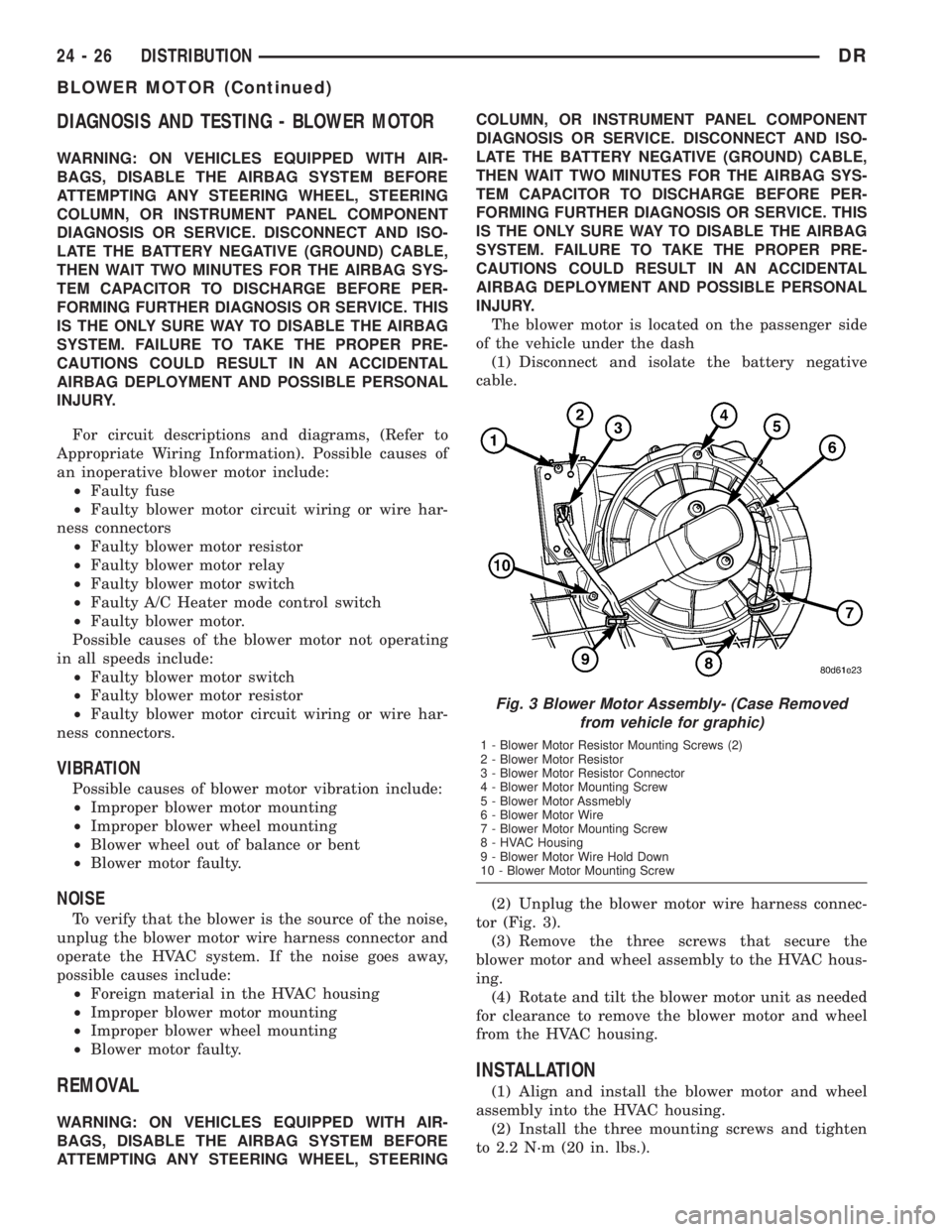
The blower motor is located on the passenger side
of the vehicle under the dash
(1) Disconnect and isolate the battery negative
cable.
(2) Unplug the blower motor wire harness connec-
tor (Fig. 3).
(3) Remove the three screws that secure the
blower motor and wheel assembly to the HVAC hous-
ing.
(4) Rotate and tilt the blower motor unit as needed
for clearance to remove the blower motor and wheel
from the HVAC housing.
INSTALLATION
(1) Align and install the blower motor and wheel
assembly into the HVAC housing.
(2) Install the three mounting screws and tighten
to 2.2 N´m (20 in. lbs.).
Fig. 3 Blower Motor Assembly- (Case Removed
from vehicle for graphic)
1 - Blower Motor Resistor Mounting Screws (2)
2 - Blower Motor Resistor
3 - Blower Motor Resistor Connector
4 - Blower Motor Mounting Screw
5 - Blower Motor Assmebly
6 - Blower Motor Wire
7 - Blower Motor Mounting Screw
8 - HVAC Housing
9 - Blower Motor Wire Hold Down
10 - Blower Motor Mounting Screw
24 - 26 DISTRIBUTIONDR
BLOWER MOTOR (Continued)
Page 2822 of 2895
(1) Remove the tape or plugs from all of the refrig-
erant line fittings. Connect the suction refrigerant
line coupler to the accumulator. (Refer to 24 - HEAT-
ING & AIR CONDITIONING/PLUMBING - STAN-
DARD PROCEDURE - A/C LINE COUPLERS)
(2) Install a new gasket and the discharge line
block fitting over the stud on the condenser inlet.
Tighten the mounting nut to 20 N´m (180 in. lbs.).
(3) Install the refrigerant line manifold to the com-
pressor. Tighten the mounting bolt to 22 N´m (200 in.
lbs.).
(4) Plug in the wire harness connector to the A/C
high pressure transducer.
(5) Connect the battery negative cable.
(6) Evacuate the refrigerant system. (Refer to 24 -
HEATING & AIR CONDITIONING/PLUMBING -
STANDARD PROCEDURE - REFRIGERANT SYS-
TEM EVACUATE)
(7) Charge the refrigerant system. (Refer to 24 -
HEATING & AIR CONDITIONING/PLUMBING -
STANDARD PROCEDURE - REFRIGERANT SYS-
TEM CHARGE)
INSTALLATION
WARNING: REVIEW THE WARNINGS AND CAU-
TIONS IN THE FRONT OF THIS SECTION BEFORE
PERFORMING THE FOLLOWING OPERATION.
(Refer to 24 - HEATING & AIR CONDITIONING/
PLUMBING - WARNING) (Refer to 24 - HEATING &
AIR CONDITIONING/PLUMBING - CAUTION)(Refer to
24 - HEATING & AIR CONDITIONING/PLUMBING -
CAUTION - REFRIGERANT HOSES/LINES/TUBES
PRECAUTIONS)
(1) Remove the tape or plugs from all of the refrig-
erant line fittings. Connect the suction line refriger-
ant line coupler to the accumulator. (Refer to 24 -
HEATING & AIR CONDITIONING/PLUMBING -
STANDARD PROCEDURE - A/C LINE COUPLERS)
(2) Install a new gasket and the discharge line
block fitting over the stud on the condenser inlet.
Tighten the mounting nut to 20 N´m (180 in. lbs.).
(3) Install the refrigerant line manifold to the com-
pressor. Tighten the mounting bolt to 22 N´m (200 in.
lbs.).
(4) Plug in the wire harness connector to the a/c
high pressure switch.
(5) Connect the battery negative cable.
(6) Evacuate the refrigerant system. (Refer to 24 -
HEATING & AIR CONDITIONING/PLUMBING -
STANDARD PROCEDURE - REFRIGERANT SYS-
TEM EVACUATE)
(7) Charge the refrigerant system. (Refer to 24 -
HEATING & AIR CONDITIONING/PLUMBING -
STANDARD PROCEDURE - REFRIGERANT SYS-
TEM CHARGE)
A/C EVAPORATOR
DESCRIPTION
The A/C evaporator is located in the HVAC hous-
ing, under the instrument panel. The evaporator coil
is positioned in the HVAC housing so that all air that
enters the housing must pass over the fins of the
evaporator before it is distributed through the sys-
tem ducts and outlets. However, air passing over the
evaporator coil fins will only be conditioned when the
compressor is engaged and circulating refrigerant
through the evaporator coil tubes.
OPERATION
Refrigerant enters the evaporator from the fixed
orifice tube as a low-temperature, low-pressure liq-
uid. As air flows over the fins of the evaporator, the
humidity in the air condenses on the fins, and the
heat from the air is absorbed by the refrigerant. Heat
absorption causes the refrigerant to boil and vapor-
ize. The refrigerant becomes a low-pressure gas when
it leaves the evaporator.
The evaporator coil cannot be repaired and, if
faulty or damaged, it must be replaced.
REMOVAL
WARNING: REVIEW THE WARNINGS AND CAU-
TIONS IN THE FRONT OF THIS SECTION BEFORE
PERFORMING THE FOLLOWING OPERATION.
(Refer to 24 - HEATING & AIR CONDITIONING/
PLUMBING - WARNING) (Refer to 24 - HEATING &
AIR CONDITIONING/PLUMBING - CAUTION)
(1) Remove the HVAC housing from the vehicle,
and disassemble the housing halves. (Refer to 24 -
HEATING & AIR CONDITIONING/DISTRIBUTION/
HVAC HOUSING - REMOVAL) (Refer to 24 - HEAT-
ING & AIR CONDITIONING/DISTRIBUTION/HVAC
HOUSING - DISASSEMBLY)
(2) Lift the A/C evaporator out of the HVAC hous-
ing (Fig. 13).
INSTALLATION
WARNING: REVIEW THE WARNINGS AND CAU-
TIONS IN THE FRONT OF THIS SECTION BEFORE
PERFORMING THE FOLLOWING OPERATION.
(Refer to 24 - HEATING & AIR CONDITIONING/
PLUMBING - WARNING) (Refer to 24 - HEATING &
AIR CONDITIONING/PLUMBING - CAUTION)(Refer to
24 - HEATING & AIR CONDITIONING/PLUMBING -
CAUTION - REFRIGERANT HOSES/LINES/TUBES
PRECAUTIONS)
DRPLUMBING 24 - 47
SUCTION LINE (Continued)
Page 2834 of 2895
problem is repaired or ceases to exist, the PCM can-
cels the code after 40 warm-up cycles. Diagnostic
trouble codes that affect vehicle emissions illuminate
the Malfunction Indicator Lamp (MIL). The MIL is
displayed as an engine icon (graphic) on the instru-
ment panel. Refer to Malfunction Indicator Lamp in
this section.
Certain criteria must be met before the PCM
stores a DTC in memory. The criteria may be a spe-
cific range of engine RPM, engine temperature,
and/or input voltage to the PCM.
The PCM might not store a DTC for a monitored
circuit even though a malfunction has occurred. This
may happen because one of the DTC criteria for the
circuit has not been met.For example,assume the
diagnostic trouble code criteria requires the PCM to
monitor the circuit only when the engine operates
between 750 and 2000 RPM. Suppose the sensor's
output circuit shorts to ground when engine operates
above 2400 RPM (resulting in 0 volt input to the
PCM). Because the condition happens at an engine
speed above the maximum threshold (2000 rpm), the
PCM will not store a DTC.
There are several operating conditions for which
the PCM monitors and sets DTC's. Refer to Moni-
tored Systems, Components, and Non-Monitored Cir-
cuits in this section.
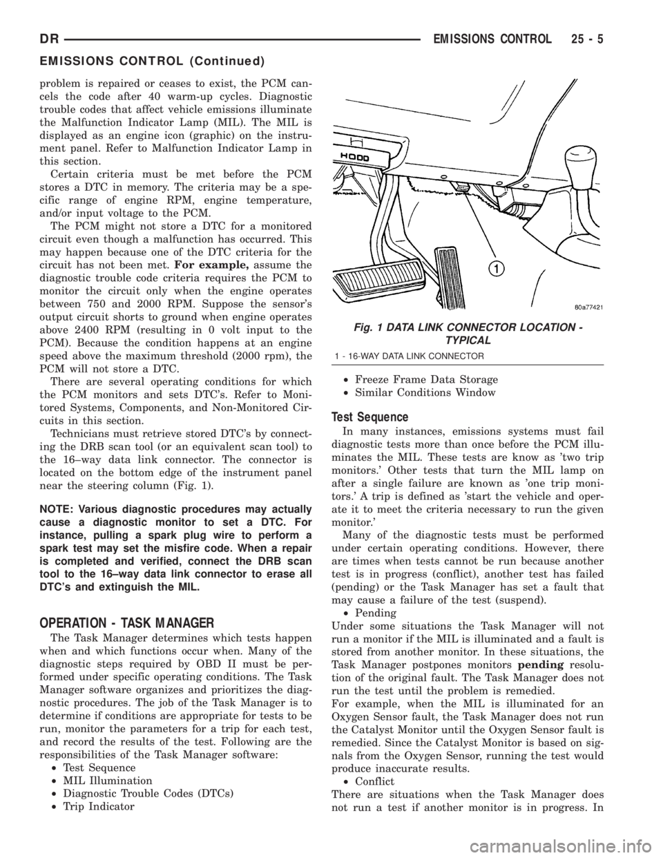
Technicians must retrieve stored DTC's by connect-
ing the DRB scan tool (or an equivalent scan tool) to
the 16±way data link connector. The connector is
located on the bottom edge of the instrument panel
near the steering column (Fig. 1).
NOTE: Various diagnostic procedures may actually
cause a diagnostic monitor to set a DTC. For
instance, pulling a spark plug wire to perform a
spark test may set the misfire code. When a repair
is completed and verified, connect the DRB scan
tool to the 16±way data link connector to erase all
DTC's and extinguish the MIL.
OPERATION - TASK MANAGER
The Task Manager determines which tests happen
when and which functions occur when. Many of the
diagnostic steps required by OBD II must be per-
formed under specific operating conditions. The Task
Manager software organizes and prioritizes the diag-
nostic procedures. The job of the Task Manager is to
determine if conditions are appropriate for tests to be
run, monitor the parameters for a trip for each test,
and record the results of the test. Following are the
responsibilities of the Task Manager software:
²Test Sequence
²MIL Illumination
²Diagnostic Trouble Codes (DTCs)
²Trip Indicator²Freeze Frame Data Storage
²Similar Conditions Window
Test Sequence
In many instances, emissions systems must fail
diagnostic tests more than once before the PCM illu-
minates the MIL. These tests are know as 'two trip
monitors.' Other tests that turn the MIL lamp on
after a single failure are known as 'one trip moni-
tors.' A trip is defined as 'start the vehicle and oper-
ate it to meet the criteria necessary to run the given
monitor.'
Many of the diagnostic tests must be performed
under certain operating conditions. However, there
are times when tests cannot be run because another
test is in progress (conflict), another test has failed
(pending) or the Task Manager has set a fault that
may cause a failure of the test (suspend).
²Pending
Under some situations the Task Manager will not
run a monitor if the MIL is illuminated and a fault is
stored from another monitor. In these situations, the
Task Manager postpones monitorspendingresolu-
tion of the original fault. The Task Manager does not
run the test until the problem is remedied.
For example, when the MIL is illuminated for an
Oxygen Sensor fault, the Task Manager does not run
the Catalyst Monitor until the Oxygen Sensor fault is
remedied. Since the Catalyst Monitor is based on sig-
nals from the Oxygen Sensor, running the test would
produce inaccurate results.
²Conflict
There are situations when the Task Manager does
not run a test if another monitor is in progress. In
Fig. 1 DATA LINK CONNECTOR LOCATION -
TYPICAL
1 - 16-WAY DATA LINK CONNECTOR
DREMISSIONS CONTROL 25 - 5
EMISSIONS CONTROL (Continued)
Page 2888 of 2895
STEM SEALS - REMOVAL, VALVE........9-377
STOP LAMP - INSTALLATION, CENTER
HIGH MOUNTED.....................8L-10
STOP LAMP - REMOVAL, CENTER HIGH
MOUNTED..........................8L-10
STOP LAMP UNIT - INSTALLATION,
CENTER HIGH MOUNTED..............8L-10
STOP LAMP UNIT - REMOVAL, CENTER
HIGH MOUNTED.....................8L-10
STORAGE BIN - INSTALLATION..........23-62
STORAGE BIN - INSTALLATION, UNDER
SEAT ..............................23-81
STORAGE BIN - REMOVAL.............23-62
STORAGE BIN - REMOVAL, UNDER SEAT . . 23-81
STORAGE BIN COVERING -
INSTALLATION, UNDER SEAT...........23-81
STORAGE BIN COVERING - REMOVAL,
UNDER SEAT........................23-81
STORAGE BIN LATCH - INSTALLATION,
UNDER SEAT........................23-81
STORAGE BIN LATCH - REMOVAL,
UNDER SEAT........................23-81
STRAP - DESCRIPTION, RADIO NOISE
SUPPRESSION GROUND................8A-8
STRAP - INSTALLATION, RADIO NOISE
SUPPRESSION GROUND...............8A-10
STRAP - OPERATION, RADIO NOISE
SUPPRESSION GROUND................8A-8
STRAP - REMOVAL, RADIO NOISE
SUPPRESSION GROUND................8A-9
STRETCH - INSPECTION, MEASURING
TIMING CHAIN.................9-279,9-405
STRIKER - INSTALLATION, LATCH . . 23-17,23-24,
23-33
STRIKER - REMOVAL, LATCH . 23-17,23-24,23-33
STRIKER / SECONDARY CATCH -
INSTALLATION, LATCH................23-48
STRIKER / SECONDARY CATCH -
REMOVAL, LATCH....................23-48
STRUCTURAL ADHESIVE LOCATIONS -
SPECIFICATIONS....................23-113
STRUCTURAL COVER - DESCRIPTION....9-143,
9-210,9-56
STRUCTURAL COVER - INSTALLATION . . . 9-143,
9-210,9-56
STRUCTURAL COVER - OPERATION.....9-143,
9-210,9-56
STRUCTURAL COVER - REMOVAL . . 9-143,9-210,
9-56
STUDS - INSTALLATION...............22-14
STUDS - REMOVAL...................22-14
SUN VISOR - INSTALLATION...........23-71
SUN VISOR - REMOVAL...............23-71
SUN VISOR SUPPORT - INSTALLATION . . . 23-72
SUN VISOR SUPPORT - REMOVAL.......23-72
SUPPLEMENTAL RESTRAINT
DEPLOYMENT - STANDARD
PROCEDURE, SERVICE AFTER A.........8O-7
SUPPLEMENTAL RESTRAINT SYSTEM -
DIAGNOSIS AND TESTING..............8O-6
SUPPLEMENTAL RESTRAINTS -
STANDARD PROCEDURE, HANDLING
NON-DEPLOYED......................8O-6
SUPPLIES - DESCRIPTION, 5 VOLT......8E-10
SUPPLIES - OPERATION, 5 VOLT........8E-11
SUPPLY TEST - DIAGNOSIS AND
TESTING, VACUUM....................8P-2
SUPPORT - INSTALLATION, SUN VISOR
. . . 23-72
SUPPORT - REMOVAL, SUN VISOR
......23-72
SUPPORT BRACKET - INSTALLATION,
REARVIEW MIRROR
..................23-71
SUPPORT BRACKET - INSTALLATION,
STEERING COLUMN OPENING
..........23-62
SUPPORT BRACKET - REMOVAL,
STEERING COLUMN OPENING
..........23-61
SUPPORT CYLINDER - INSTALLATION
....23-49
SUPPORT CYLINDER - INSTALLATION,
LOAD FLOOR
........................23-73
SUPPORT CYLINDER - REMOVAL
........23-48
SUPPORT CYLINDER - REMOVAL, LOAD
FLOOR
.............................23-73
SUPPORT PLATE - INSTALLATION
........5-29
SUPPORT PLATE - REMOVAL
............5-29
SUPPRESSION GROUND STRAP -
DESCRIPTION, RADIO NOISE
............8A-8
SUPPRESSION GROUND STRAP -
INSTALLATION, RADIO NOISE
...........8A-10SUPPRESSION GROUND STRAP -
OPERATION, RADIO NOISE..............8A-8
SUPPRESSION GROUND STRAP -
REMOVAL, RADIO NOISE...............8A-9
SURFACE PREPARATION - STANDARD
PROCEDURE, ENGINE GASKET...........9-10
SURROUND - INSTALLATION,
INSTRUMENT PANEL LOWER...........23-60
SURROUND - REMOVAL, INSTRUMENT
PANEL LOWER......................23-60
SUSPENSION - DESCRIPTION, GEAR -
INDEPENDENT FRONT.................19-16
SUSPENSION - INSTALLATION, GEAR -
INDEPENDENT FRONT.................19-17
SUSPENSION - REMOVAL, GEAR -
INDEPENDENT FRONT.................19-16
SUSPENSION - STANDARD PROCEDURE,
ALIGNMENT LINK/COIL..................2-5
SUSPENSION ARM - INSTALLATION,
LOWER.............................2-35
SUSPENSION ARM - REMOVAL, LOWER . . . 2-35
SUSPENSION, SPECIAL TOOLS - FRONT . . . 2-11
SWITCH - DESCRIPTION................8P-8
SWITCH - DESCRIPTION, BACKUP LAMP . . . 8L-7
SWITCH - DESCRIPTION, BLOWER
MOTOR............................24-18
SWITCH - DESCRIPTION, BRAKE LAMP....8L-8
SWITCH - DESCRIPTION, CLUTCH
PEDAL POSITION.....................6-14
SWITCH - DESCRIPTION, DOOR AJAR....8L-25
SWITCH - DESCRIPTION, DRIVER SEAT . . . 8N-15
SWITCH - DESCRIPTION, HAZARD.......8L-13
SWITCH - DESCRIPTION, HEADLAMP....8L-14
SWITCH - DESCRIPTION, HEATED SEAT . . . 8G-7
SWITCH - DESCRIPTION, HORN..........8H-2
SWITCH - DESCRIPTION, IGNITION.......19-9
SWITCH - DESCRIPTION, KEY-IN
IGNITION...........................19-11
SWITCH - DESCRIPTION, LUMBAR
CONTROL..........................8N-19
SWITCH - DESCRIPTION, OVERDRIVE . . . 21-218,
21-397,21-568
SWITCH - DESCRIPTION, PASSENGER
AIRBAG ON/OFF.....................8O-38
SWITCH - DESCRIPTION, PASSENGER
SEAT ..............................8N-16
SWITCH - DESCRIPTION, POWER
STEERING PRESSURE.................19-45
SWITCH - DESCRIPTION, SEAT BELT.....8O-46
SWITCH - DESCRIPTION, SELECTOR....21-685,
21-719
SWITCH - DESCRIPTION, WASHER
FLUID LEVEL.........................8R-9
SWITCH - DIAGNOSIS AND TESTING,
BACKUP LAMP.......................8L-8
SWITCH - DIAGNOSIS AND TESTING,
BLOWER MOTOR....................24-18
SWITCH - DIAGNOSIS AND TESTING,
BRAKE LAMP........................8L-9
SWITCH - DIAGNOSIS AND TESTING,
CLUTCH PEDAL POSITION..............6-14
SWITCH - DIAGNOSIS AND TESTING,
DRIVER SEAT.......................8N-15
SWITCH - DIAGNOSIS AND TESTING,
HEATED SEAT ........................8G-8
SWITCH - DIAGNOSIS AND TESTING,
HORN..............................8H-2
SWITCH - DIAGNOSIS AND TESTING,
IGNITION............................19-9
SWITCH - DIAGNOSIS AND TESTING,
MULTI-FUNCTION....................8L-18
SWITCH - DIAGNOSIS AND TESTING,
PASSENGER SEAT....................8N-17
SWITCH - DIAGNOSIS AND TESTING,
POWER LOCK........................8N-4
SWITCH - DIAGNOSIS AND TESTING,
POWER MIRROR....................8N-13
SWITCH - DIAGNOSIS AND TESTING,
SEAT BELT .........................8O-47
SWITCH - DIAGNOSIS AND TESTING,
WINDOW...........................8N-22
SWITCH - INSTALLATION
...............8P-9
SWITCH - INSTALLATION, ADJUSTABLE
PEDAL
...............................5-6
SWITCH - INSTALLATION, BLOWER
MOTOR
............................24-19
SWITCH - INSTALLATION, BRAKE LAMP
. . 8L-10
SWITCH - INSTALLATION, DRIVER SEAT
. . 8N-16SWITCH - INSTALLATION, HEADLAMP....8L-14
SWITCH - INSTALLATION, HEATED SEAT . . . 8G-9
SWITCH - INSTALLATION, IGNITION......19-11
SWITCH - INSTALLATION, MULTI-
FUNCTION..........................8L-19
SWITCH - INSTALLATION, OVERDRIVE . . 21-219,
21-397,21-569
SWITCH - INSTALLATION, PASSENGER
AIRBAG ON/OFF.....................8O-39
SWITCH - INSTALLATION, PASSENGER
SEAT ..............................8N-18
SWITCH - INSTALLATION, POWER LOCK . . . 8N-4
SWITCH - INSTALLATION, WASHER
FLUID LEVEL........................8R-11
SWITCH - INSTALLATION, WINDOW.....8N-23
SWITCH - OPERATION.................8P-8
SWITCH - OPERATION, BACKUP LAMP....8L-8
SWITCH - OPERATION, BLOWER MOTOR . . 24-18
SWITCH - OPERATION, BRAKE LAMP......8L-8
SWITCH - OPERATION, CLUTCH PEDAL
POSITION...........................6-14
SWITCH - OPERATION, DOOR AJAR......8L-25
SWITCH - OPERATION, DRIVER SEAT....8N-15
SWITCH - OPERATION, HAZARD.........8L-13
SWITCH - OPERATION, HEADLAMP......8L-14
SWITCH - OPERATION, HEATED SEAT.....8G-8
SWITCH - OPERATION, IGNITION.........19-9
SWITCH - OPERATION, LUMBAR
CONTROL............................8N-19
SWITCH - OPERATION, OVERDRIVE....21-218,
21-397,21-568
SWITCH - OPERATION, PASSENGER
AIRBAG ON/OFF.....................8O-38
SWITCH - OPERATION, PASSENGER
SEAT ..............................8N-17
SWITCH - OPERATION, POWER
STEERING PRESSURE.................19-45
SWITCH - OPERATION, SEAT BELT.......8O-46
SWITCH - OPERATION, SELECTOR.....21-685,
21-719
SWITCH - OPERATION, WASHER FLUID
LEVEL..............................8R-9
SWITCH - REMOVAL...................8P-9
SWITCH - REMOVAL, ADJUSTABLE
PEDAL...............................5-6
SWITCH - REMOVAL, BLOWER MOTOR . . . 24-19
SWITCH - REMOVAL, BRAKE LAMP.......8L-9
SWITCH - REMOVAL, DRIVER SEAT......8N-16
SWITCH - REMOVAL, HEADLAMP........8L-14
SWITCH - REMOVAL, HEATED SEAT.......8G-9
SWITCH - REMOVAL, IGNITION.........19-10
SWITCH - REMOVAL, LUMBAR
CONTROL..........................8N-19
SWITCH - REMOVAL, MULTI-FUNCTION . . . 8L-18
SWITCH - REMOVAL, OVERDRIVE......21-219,
21-397,21-568
SWITCH - REMOVAL, PASSENGER
AIRBAG ON/OFF.....................8O-39
SWITCH - REMOVAL, PASSENGER SEAT . . 8N-17
SWITCH - REMOVAL, POWER LOCK......8N-4
SWITCH - REMOVAL, POWER MIRROR . . . 8N-13
SWITCH - REMOVAL, WASHER FLUID
LEVEL.............................8R-10
SWITCH - REMOVAL, WINDOW.........8N-23
SWITCH AND KEY LOCK CYLINDER -
DIAGNOSIS AND TESTING, IGNITION.....19-11
SWITCH BEZEL - INSTALLATION,
INSTRUMENT PANEL HEADLAMP........23-57
SWITCH BEZEL - REMOVAL,
INSTRUMENT PANEL HEADLAMP........23-57
SWITCH OPERATING MODES,
STANDARD PROCEDURE -
CONFIGURING A NEW MODULE..........8Q-3
SWITCH VALVE - DESCRIPTION,
SOLENOID.........................21-574
SWITCH VALVE - OPERATION, SOLENOID . 21-574
SWITCHES - DESCRIPTION, REMOTE.....8A-10
SWITCHES - DIAGNOSIS AND TESTING,
REMOTE...........................8A-11
SWITCHES - INSTALLATION, REMOTE....8A-12
SWITCHES - OPERATION, REMOTE
......8A-10
SWITCHES - REMOVAL, REMOTE
........8A-12
SYMBOLS - DESCRIPTION,
INTERNATIONAL
....................Intro.-6
SYMBOLS - DESCRIPTION,
INTERNATIONAL
.......................0-1
TABLE, SPECIFICATIONS - A/C
APPLICATION
........................24-7
DRINDEX 33
Description Group-Page Description Group-Page Description Group-Page