2003 DODGE RAM sensor
[x] Cancel search: sensorPage 2059 of 2895
OVERDRIVE UNIT
REMOVAL
(1) Shift transmission into PARK.
(2) Raise vehicle.
(3) Remove transfer case, if equipped.
(4) Mark propeller shaft universal joint(s) and axle
pinion yoke, or the companion flange and flange
yoke, for alignment reference at installation, if neces-
sary.
(5) Disconnect and remove the rear propeller shaft,
if necessary. (Refer to 3 - DIFFERENTIAL & DRIV-
ELINE/PROPELLER SHAFT/PROPELLER SHAFT -
REMOVAL)
(6) Remove transmission oil pan, remove gasket,
drain oil and reinstall pan.
(7) If overdrive unit had malfunctioned, or if fluid
is contaminated, remove entire transmission. If diag-
nosis indicated overdrive problems only, remove just
the overdrive unit.
(8) Support transmission with transmission jack.
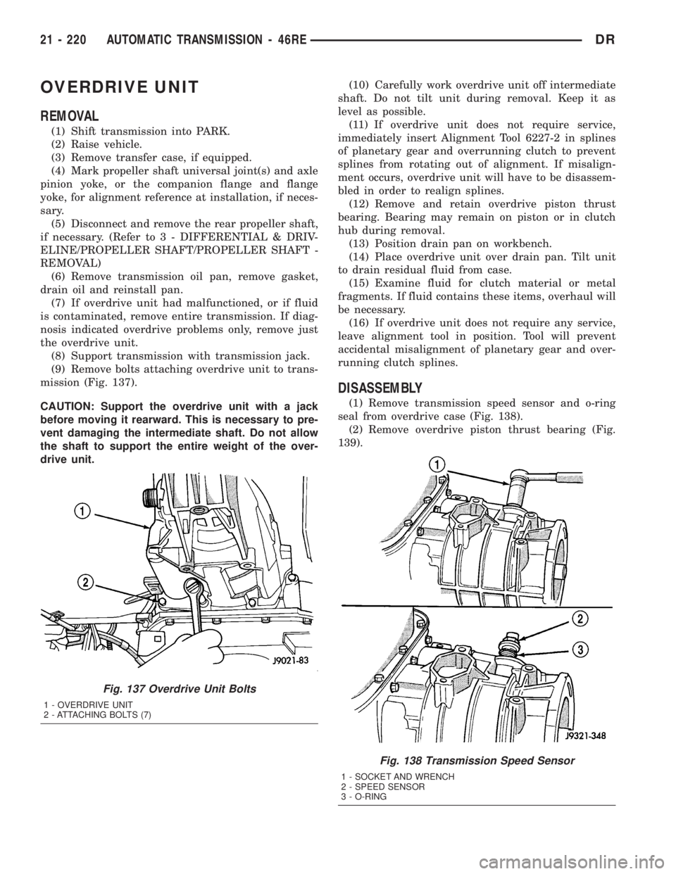
(9) Remove bolts attaching overdrive unit to trans-
mission (Fig. 137).
CAUTION: Support the overdrive unit with a jack
before moving it rearward. This is necessary to pre-
vent damaging the intermediate shaft. Do not allow
the shaft to support the entire weight of the over-
drive unit.(10) Carefully work overdrive unit off intermediate
shaft. Do not tilt unit during removal. Keep it as
level as possible.
(11) If overdrive unit does not require service,
immediately insert Alignment Tool 6227-2 in splines
of planetary gear and overrunning clutch to prevent
splines from rotating out of alignment. If misalign-
ment occurs, overdrive unit will have to be disassem-
bled in order to realign splines.
(12) Remove and retain overdrive piston thrust
bearing. Bearing may remain on piston or in clutch
hub during removal.
(13) Position drain pan on workbench.
(14) Place overdrive unit over drain pan. Tilt unit
to drain residual fluid from case.
(15) Examine fluid for clutch material or metal
fragments. If fluid contains these items, overhaul will
be necessary.
(16) If overdrive unit does not require any service,
leave alignment tool in position. Tool will prevent
accidental misalignment of planetary gear and over-
running clutch splines.
DISASSEMBLY
(1) Remove transmission speed sensor and o-ring
seal from overdrive case (Fig. 138).
(2) Remove overdrive piston thrust bearing (Fig.
139).
Fig. 137 Overdrive Unit Bolts
1 - OVERDRIVE UNIT
2 - ATTACHING BOLTS (7)
Fig. 138 Transmission Speed Sensor
1 - SOCKET AND WRENCH
2 - SPEED SENSOR
3 - O-RING
21 - 220 AUTOMATIC TRANSMISSION - 46REDR
Page 2075 of 2895
OD THRUST PLATE SELECTION
(1) Place overdrive unit in vertical position. Mount
it on blocks, or in workbench with appropriate size
mounting hole cut into it. Be sure unit is facing
upward for access to direct clutch hub. Also be sure
output shaft is not loaded and internal components
are moved rearward for accurate measurement.
(2) Determine correct thickness overdrive piston
thrust plate as follows:
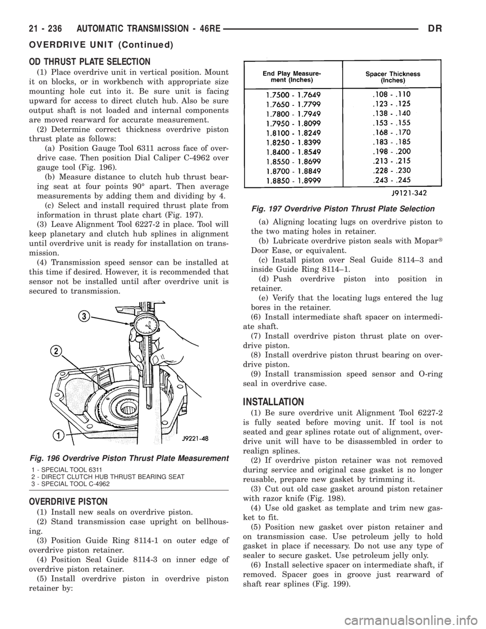
(a) Position Gauge Tool 6311 across face of over-
drive case. Then position Dial Caliper C-4962 over
gauge tool (Fig. 196).
(b) Measure distance to clutch hub thrust bear-
ing seat at four points 90É apart. Then average
measurements by adding them and dividing by 4.
(c) Select and install required thrust plate from
information in thrust plate chart (Fig. 197).
(3) Leave Alignment Tool 6227-2 in place. Tool will
keep planetary and clutch hub splines in alignment
until overdrive unit is ready for installation on trans-
mission.
(4) Transmission speed sensor can be installed at
this time if desired. However, it is recommended that
sensor not be installed until after overdrive unit is
secured to transmission.
OVERDRIVE PISTON
(1) Install new seals on overdrive piston.
(2) Stand transmission case upright on bellhous-
ing.
(3) Position Guide Ring 8114-1 on outer edge of
overdrive piston retainer.
(4) Position Seal Guide 8114-3 on inner edge of
overdrive piston retainer.
(5) Install overdrive piston in overdrive piston
retainer by:(a) Aligning locating lugs on overdrive piston to
the two mating holes in retainer.
(b) Lubricate overdrive piston seals with Mopart
Door Ease, or equivalent.
(c) Install piston over Seal Guide 8114±3 and
inside Guide Ring 8114±1.
(d) Push overdrive piston into position in
retainer.
(e) Verify that the locating lugs entered the lug
bores in the retainer.
(6) Install intermediate shaft spacer on intermedi-
ate shaft.
(7) Install overdrive piston thrust plate on over-
drive piston.
(8) Install overdrive piston thrust bearing on over-
drive piston.
(9) Install transmission speed sensor and O-ring
seal in overdrive case.
INSTALLATION
(1) Be sure overdrive unit Alignment Tool 6227-2
is fully seated before moving unit. If tool is not
seated and gear splines rotate out of alignment, over-
drive unit will have to be disassembled in order to
realign splines.
(2) If overdrive piston retainer was not removed
during service and original case gasket is no longer
reusable, prepare new gasket by trimming it.
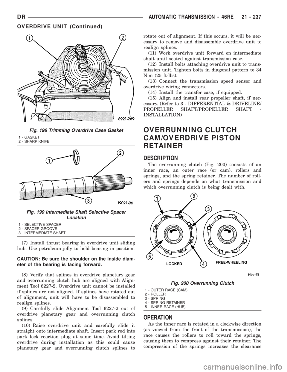
(3) Cut out old case gasket around piston retainer
with razor knife (Fig. 198).
(4) Use old gasket as template and trim new gas-
ket to fit.
(5) Position new gasket over piston retainer and
on transmission case. Use petroleum jelly to hold
gasket in place if necessary. Do not use any type of
sealer to secure gasket. Use petroleum jelly only.
(6) Install selective spacer on intermediate shaft, if
removed. Spacer goes in groove just rearward of
shaft rear splines (Fig. 199).
Fig. 196 Overdrive Piston Thrust Plate Measurement
1 - SPECIAL TOOL 6311
2 - DIRECT CLUTCH HUB THRUST BEARING SEAT
3 - SPECIAL TOOL C-4962
Fig. 197 Overdrive Piston Thrust Plate Selection
21 - 236 AUTOMATIC TRANSMISSION - 46REDR
OVERDRIVE UNIT (Continued)
Page 2076 of 2895
(7) Install thrust bearing in overdrive unit sliding
hub. Use petroleum jelly to hold bearing in position.
CAUTION: Be sure the shoulder on the inside diam-
eter of the bearing is facing forward.
(8) Verify that splines in overdrive planetary gear
and overrunning clutch hub are aligned with Align-
ment Tool 6227-2. Overdrive unit cannot be installed
if splines are not aligned. If splines have rotated out
of alignment, unit will have to be disassembled to
realign splines.
(9) Carefully slide Alignment Tool 6227-2 out of
overdrive planetary gear and overrunning clutch
splines.
(10) Raise overdrive unit and carefully slide it
straight onto intermediate shaft. Insert park rod into
park lock reaction plug at same time. Avoid tilting
overdrive during installation as this could cause
planetary gear and overrunning clutch splines torotate out of alignment. If this occurs, it will be nec-
essary to remove and disassemble overdrive unit to
realign splines.
(11) Work overdrive unit forward on intermediate
shaft until seated against transmission case.
(12) Install bolts attaching overdrive unit to trans-
mission unit. Tighten bolts in diagonal pattern to 34
N´m (25 ft-lbs).
(13) Connect the transmission speed sensor and
overdrive wiring connectors.
(14) Install the transfer case, if equipped.
(15) Align and install rear propeller shaft, if nec-
essary. (Refer to 3 - DIFFERENTIAL & DRIVELINE/
PROPELLER SHAFT/PROPELLER SHAFT -
INSTALLATION)
OVERRUNNING CLUTCH
CAM/OVERDRIVE PISTON
RETAINER
DESCRIPTION
The overrunning clutch (Fig. 200) consists of an
inner race, an outer race (or cam), rollers and
springs, and the spring retainer. The number of roll-
ers and springs depends on what transmission and
which overrunning clutch is being dealt with.
OPERATION
As the inner race is rotated in a clockwise direction
(as viewed from the front of the transmission), the
race causes the rollers to roll toward the springs,
causing them to compress against their retainer. The
compression of the springs increases the clearance
Fig. 198 Trimming Overdrive Case Gasket
1 - GASKET
2 - SHARP KNIFE
Fig. 199 Intermediate Shaft Selective Spacer
Location
1 - SELECTIVE SPACER
2 - SPACER GROOVE
3 - INTERMEDIATE SHAFT
Fig. 200 Overrunning Clutch
1 - OUTER RACE (CAM)
2 - ROLLER
3 - SPRING
4 - SPRING RETAINER
5 - INNER RACE (HUB)
DRAUTOMATIC TRANSMISSION - 46RE 21 - 237
OVERDRIVE UNIT (Continued)
Page 2093 of 2895
stant ON, or duty cycle. The variable force and pulse-
width modulated versions utilize similar methods to
control the current flow through the solenoid to posi-
tion the solenoid plunger at a desired position some-
where between full ON and full OFF. The constant
ON and duty cycled versions control the voltage
across the solenoid to allow either full flow or no flow
through the solenoid's valve.
OPERATION
When an electrical current is applied to the sole-
noid coil, a magnetic field is created which produces
an attraction to the plunger, causing the plunger to
move and work against the spring pressure and the
load applied by the fluid the valve is controlling. The
plunger is normally directly attached to the valve
which it is to operate. When the current is removed
from the coil, the attraction is removed and the
plunger will return to its original position due to
spring pressure.
The plunger is made of a conductive material and
accomplishes this movement by providing a path for
the magnetic field to flow. By keeping the air gap
between the plunger and the coil to the minimum
necessary to allow free movement of the plunger, the
magnetic field is maximized.
SPEED SENSOR
DESCRIPTION
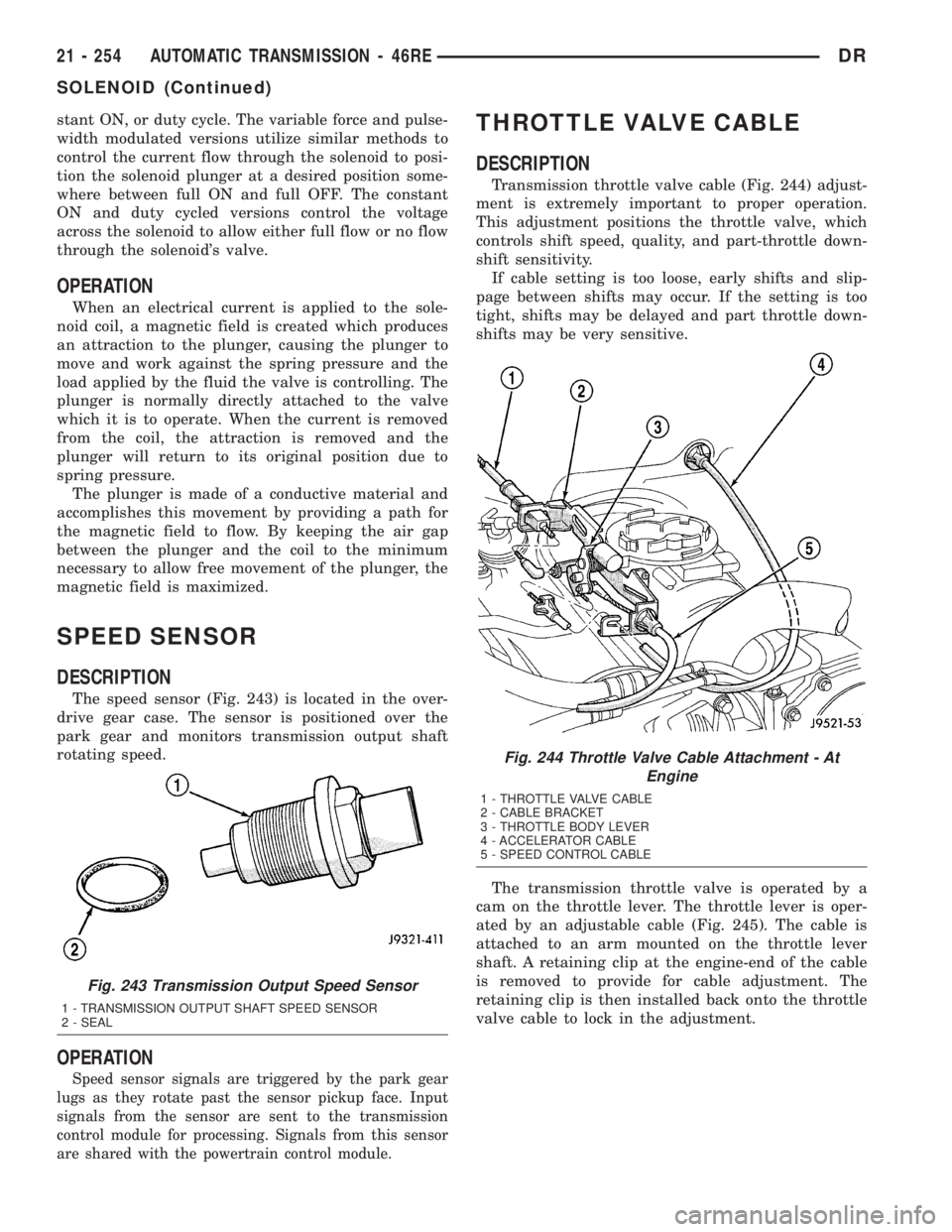
The speed sensor (Fig. 243) is located in the over-
drive gear case. The sensor is positioned over the
park gear and monitors transmission output shaft
rotating speed.
OPERATION
Speed sensor signals are triggered by the park gear
lugs as they rotate past the sensor pickup face. Input
signals from the sensor are sent to the transmission
control module for processing. Signals from this sensor
are shared with the powertrain control module.
THROTTLE VALVE CABLE
DESCRIPTION
Transmission throttle valve cable (Fig. 244) adjust-
ment is extremely important to proper operation.
This adjustment positions the throttle valve, which
controls shift speed, quality, and part-throttle down-
shift sensitivity.
If cable setting is too loose, early shifts and slip-
page between shifts may occur. If the setting is too
tight, shifts may be delayed and part throttle down-
shifts may be very sensitive.
The transmission throttle valve is operated by a
cam on the throttle lever. The throttle lever is oper-
ated by an adjustable cable (Fig. 245). The cable is
attached to an arm mounted on the throttle lever
shaft. A retaining clip at the engine-end of the cable
is removed to provide for cable adjustment. The
retaining clip is then installed back onto the throttle
valve cable to lock in the adjustment.
Fig. 243 Transmission Output Speed Sensor
1 - TRANSMISSION OUTPUT SHAFT SPEED SENSOR
2 - SEAL
Fig. 244 Throttle Valve Cable Attachment - At
Engine
1 - THROTTLE VALVE CABLE
2 - CABLE BRACKET
3 - THROTTLE BODY LEVER
4 - ACCELERATOR CABLE
5 - SPEED CONTROL CABLE
21 - 254 AUTOMATIC TRANSMISSION - 46REDR
SOLENOID (Continued)
Page 2102 of 2895
tank. The valve prevents fluid drainback when the
vehicle is parked for lengthy periods. The valve check
ball is spring loaded and has an opening pressure of
approximately 2 psi.
The valve is serviced as an assembly; it is not repair-
able. Do not clean the valve if restricted, or contami-
nated by sludge, or debris. If the valve fails, or if a
transmission malfunction occurs that generates signifi-
cant amounts of sludge and/or clutch particles and
metal shavings, the valve must be replaced.
If the valve is restricted, installed backwards, or in
the wrong line, it will cause an overheating condition
and possible transmission failure.
CAUTION: The drainback valve is a one-way flow
device. It must be properly oriented in terms of flow
direction for the cooler to function properly. The
valve must be installed in the pressure line. Other-
wise flow will be blocked and would cause an over-
heating condition and eventual transmission failure.
TRANSMISSION RANGE
SENSOR
DESCRIPTION
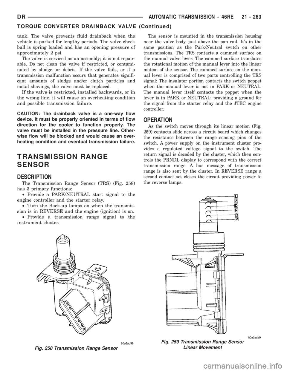
The Transmission Range Sensor (TRS) (Fig. 258)
has 3 primary functions:
²Provide a PARK/NEUTRAL start signal to the
engine controller and the starter relay.
²Turn the Back-up lamps on when the transmis-
sion is in REVERSE and the engine (ignition) is on.
²Provide a transmission range signal to the
instrument cluster.
The sensor is mounted in the transmission housing
near the valve body, just above the pan rail. It's in the
same position as the Park/Neutral switch on other
transmissions. The TRS contacts a cammed surface on
the manual valve lever. The cammed surface translates
the rotational motion of the manual lever into the linear
motion of the sensor. The cammed surface on the man-
ual lever is comprised of two parts controlling the TRS
signal: The insulator portion contacts the switch poppet
when the manual lever is not in PARK or NEUTRAL.
The manual lever itself contacts the poppet when the
lever is in PARK or NEUTRAL; providing a ground for
the signal from the starter relay and the JTEC engine
controller.
OPERATION
As the switch moves through its linear motion (Fig.
259) contacts slide across a circuit board which changes
the resistance between the range sensing pins of the
switch. A power supply on the instrument cluster pro-
vides a regulated voltage signal to the switch. The
return signal is decoded by the cluster, which then con-
trols the PRNDL display to correspond with the correct
transmission range. A bus message of transmission
range is also sent by the cluster. In REVERSE range a
second contact set closes the circuit providing power to
the reverse lamps.
Fig. 258 Transmission Range Sensor
Fig. 259 Transmission Range Sensor
Linear Movement
DRAUTOMATIC TRANSMISSION - 46RE 21 - 263
TORQUE CONVERTER DRAINBACK VALVE (Continued)
Page 2103 of 2895
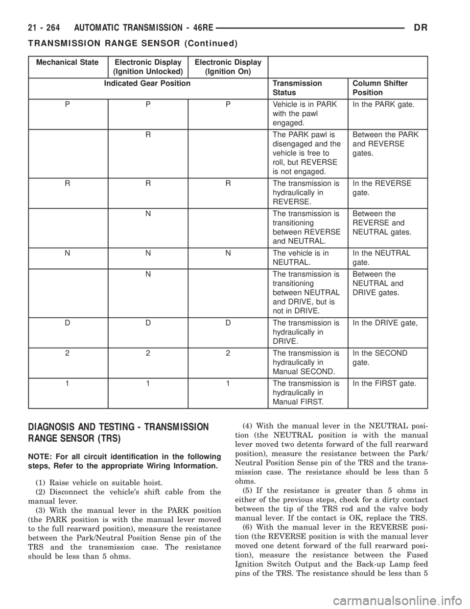
Mechanical State Electronic Display
(Ignition Unlocked)Electronic Display
(Ignition On)
Indicated Gear Position Transmission
StatusColumn Shifter
Position
P P P Vehicle is in PARK
with the pawl
engaged.In the PARK gate.
R The PARK pawl is
disengaged and the
vehicle is free to
roll, but REVERSE
is not engaged.Between the PARK
and REVERSE
gates.
R R R The transmission is
hydraulically in
REVERSE.In the REVERSE
gate.
N The transmission is
transitioning
between REVERSE
and NEUTRAL.Between the
REVERSE and
NEUTRAL gates.
N N N The vehicle is in
NEUTRAL.In the NEUTRAL
gate.
N The transmission is
transitioning
between NEUTRAL
and DRIVE, but is
not in DRIVE.Between the
NEUTRAL and
DRIVE gates.
D D D The transmission is
hydraulically in
DRIVE.In the DRIVE gate,
2 2 2 The transmission is
hydraulically in
Manual SECOND.In the SECOND
gate.
1 1 1 The transmission is
hydraulically in
Manual FIRST.In the FIRST gate.
DIAGNOSIS AND TESTING - TRANSMISSION
RANGE SENSOR (TRS)
NOTE: For all circuit identification in the following
steps, Refer to the appropriate Wiring Information.
(1) Raise vehicle on suitable hoist.
(2) Disconnect the vehicle's shift cable from the
manual lever.
(3) With the manual lever in the PARK position
(the PARK position is with the manual lever moved
to the full rearward position), measure the resistance
between the Park/Neutral Position Sense pin of the
TRS and the transmission case. The resistance
should be less than 5 ohms.(4) With the manual lever in the NEUTRAL posi-
tion (the NEUTRAL position is with the manual
lever moved two detents forward of the full rearward
position), measure the resistance between the Park/
Neutral Position Sense pin of the TRS and the trans-
mission case. The resistance should be less than 5
ohms.
(5) If the resistance is greater than 5 ohms in
either of the previous steps, check for a dirty contact
between the tip of the TRS rod and the valve body
manual lever. If the contact is OK, replace the TRS.
(6) With the manual lever in the REVERSE posi-
tion (the REVERSE position is with the manual lever
moved one detent forward of the full rearward posi-
tion), measure the resistance between the Fused
Ignition Switch Output and the Back-up Lamp feed
pins of the TRS. The resistance should be less than 5
21 - 264 AUTOMATIC TRANSMISSION - 46REDR
TRANSMISSION RANGE SENSOR (Continued)
Page 2104 of 2895
ohms. If the resistance is greater than 5 ohms,
replace the TRS.
(7) With the manual lever in the PARK position
(the PARK position is with the manual lever moved
to the full rearward position), measure the resistance
between the Transmission Range Sensor MUX and
the Transmission Range Sensor 5V Supply pins of
the TRS. The resistance should be 522.2 ohms. If the
resistance is not correct, replace the TRS.
(8) With the manual lever in the REVERSE posi-
tion (the REVERSE position is with the manual lever
moved one detent forward of the full rearward posi-
tion), measure the resistance between the Transmis-
sion Range Sensor MUX and the Transmission Range
Sensor 5V Supply pins of the TRS. The resistance
should be 206.2 ohms. If the resistance is not correct,
replace the TRS.
(9) With the manual lever in the NEUTRAL posi-
tion (the NEUTRAL position is with the manual
lever moved two detents forward of the full rearward
position), measure the resistance between the Trans-
mission Range Sensor MUX and the Transmission
Range Sensor 5V Supply pins of the TRS. The resis-
tance should be 108.6 ohms. If the resistance is not
correct, replace the TRS.
(10) With the manual lever in the DRIVE position
(the DRIVE position is with the manual lever moved
three detents forward of the full rearward position),
measure the resistance between the Transmission
Range Sensor MUX and the Transmission Range
Sensor 5V Supply pins of the TRS. The resistance
should be 59.9 ohms. If the resistance is not correct,
replace the TRS.
(11) With the manual lever in the SECOND posi-
tion (the SECOND position is with the manual lever
moved one detent rearward of the full forward posi-
tion), measure the resistance between the Transmis-
sion Range Sensor MUX and the Back-up Lamp feed
pins of the TRS. The resistance should be 31.9 ohms.
If the resistance is not correct, replace the TRS.
(12) With the manual lever in the LOW position
(the LOW position is with the manual lever moved to
the full forward position), measure the resistance
between the Transmission Range Sensor MUX and
the Back-up Lamp feed pins of the TRS. The resis-
tance should be 13.7 ohms. If the resistance is not
correct, replace the TRS.
REMOVAL
(1) Raise vehicle and position drain pan under the
transmission range sensor (TRS).
(2) Move the transmission manual lever to the
manual LOW position. The manual LOW position is
with the manual lever in the forward-most detent.
(3) Disengage the wiring connector from the TRS.(4) Remove the two screws holding the TRS to the
TRS mounting bracket.
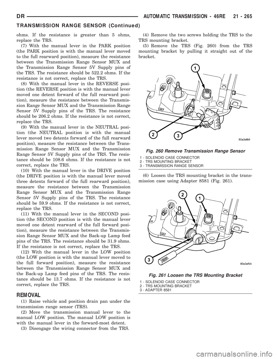
(5) Remove the TRS (Fig. 260) from the TRS
mounting bracket by pulling it straight out of the
bracket.
(6) Loosen the TRS mounting bracket in the trans-
mission case using Adapter 8581 (Fig. 261).
Fig. 260 Remove Transmission Range Sensor
1 - SOLENOID CASE CONNECTOR
2 - TRS MOUNTING BRACKET
3 - TRANSMISSION RANGE SENSOR
Fig. 261 Loosen the TRS Mounting Bracket
1 - SOLENOID CASE CONNECTOR
2 - TRS MOUNTING BRACKET
3 - ADAPTER 8581
DRAUTOMATIC TRANSMISSION - 46RE 21 - 265
TRANSMISSION RANGE SENSOR (Continued)
Page 2105 of 2895
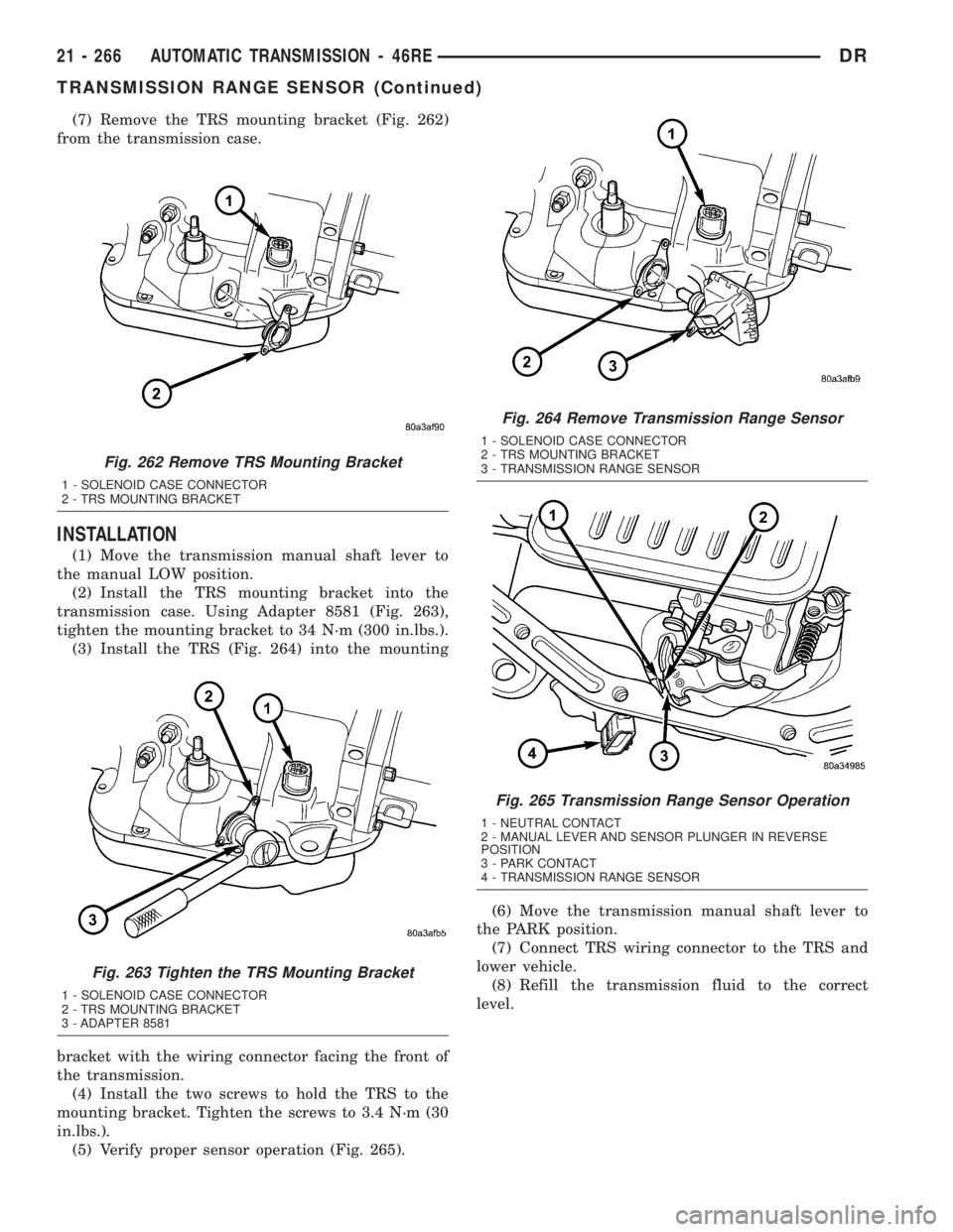
(7) Remove the TRS mounting bracket (Fig. 262)
from the transmission case.
INSTALLATION
(1) Move the transmission manual shaft lever to
the manual LOW position.
(2) Install the TRS mounting bracket into the
transmission case. Using Adapter 8581 (Fig. 263),
tighten the mounting bracket to 34 N´m (300 in.lbs.).
(3) Install the TRS (Fig. 264) into the mounting
bracket with the wiring connector facing the front of
the transmission.
(4) Install the two screws to hold the TRS to the
mounting bracket. Tighten the screws to 3.4 N´m (30
in.lbs.).
(5) Verify proper sensor operation (Fig. 265).(6) Move the transmission manual shaft lever to
the PARK position.
(7) Connect TRS wiring connector to the TRS and
lower vehicle.
(8) Refill the transmission fluid to the correct
level.
Fig. 262 Remove TRS Mounting Bracket
1 - SOLENOID CASE CONNECTOR
2 - TRS MOUNTING BRACKET
Fig. 263 Tighten the TRS Mounting Bracket
1 - SOLENOID CASE CONNECTOR
2 - TRS MOUNTING BRACKET
3 - ADAPTER 8581
Fig. 264 Remove Transmission Range Sensor
1 - SOLENOID CASE CONNECTOR
2 - TRS MOUNTING BRACKET
3 - TRANSMISSION RANGE SENSOR
Fig. 265 Transmission Range Sensor Operation
1 - NEUTRAL CONTACT
2 - MANUAL LEVER AND SENSOR PLUNGER IN REVERSE
POSITION
3 - PARK CONTACT
4 - TRANSMISSION RANGE SENSOR
21 - 266 AUTOMATIC TRANSMISSION - 46REDR
TRANSMISSION RANGE SENSOR (Continued)