Page 2323 of 2895

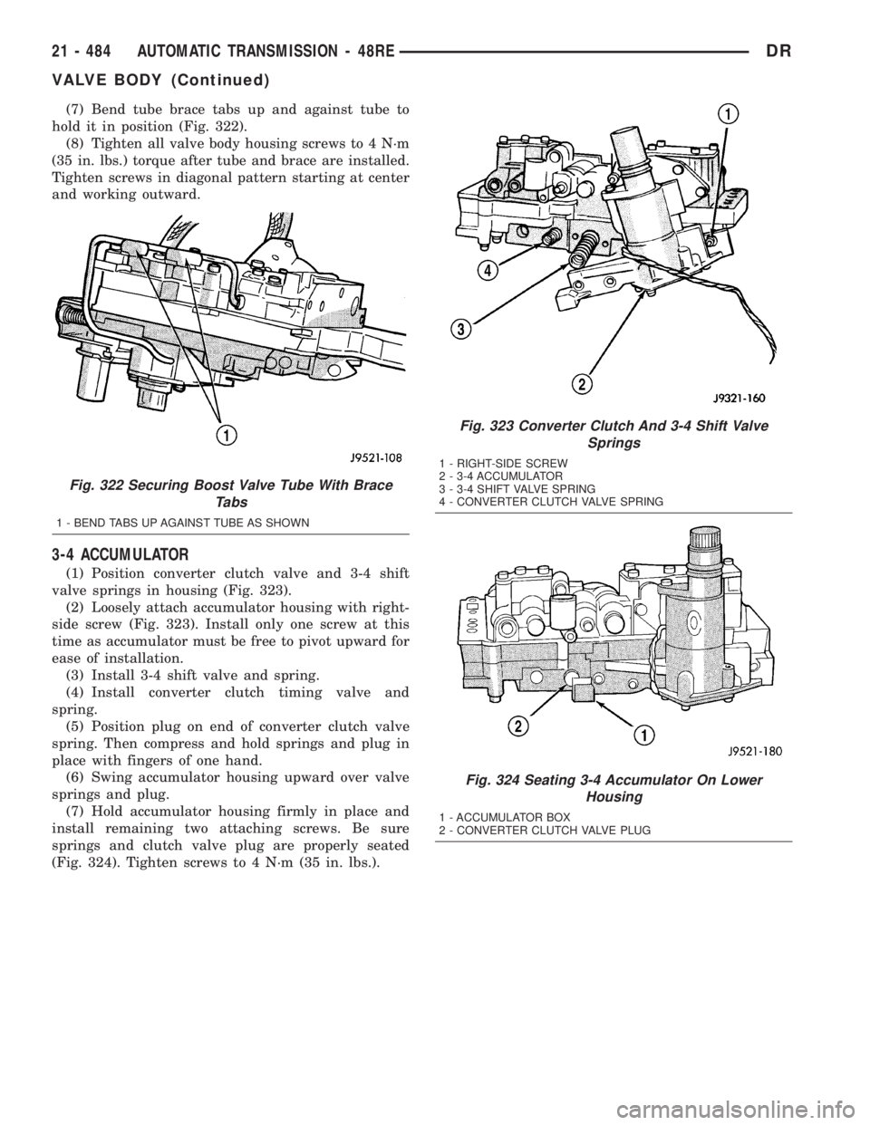
(7) Bend tube brace tabs up and against tube to
hold it in position (Fig. 322).
(8) Tighten all valve body housing screws to 4 N´m
(35 in. lbs.) torque after tube and brace are installed.
Tighten screws in diagonal pattern starting at center
and working outward.
3-4 ACCUMULATOR
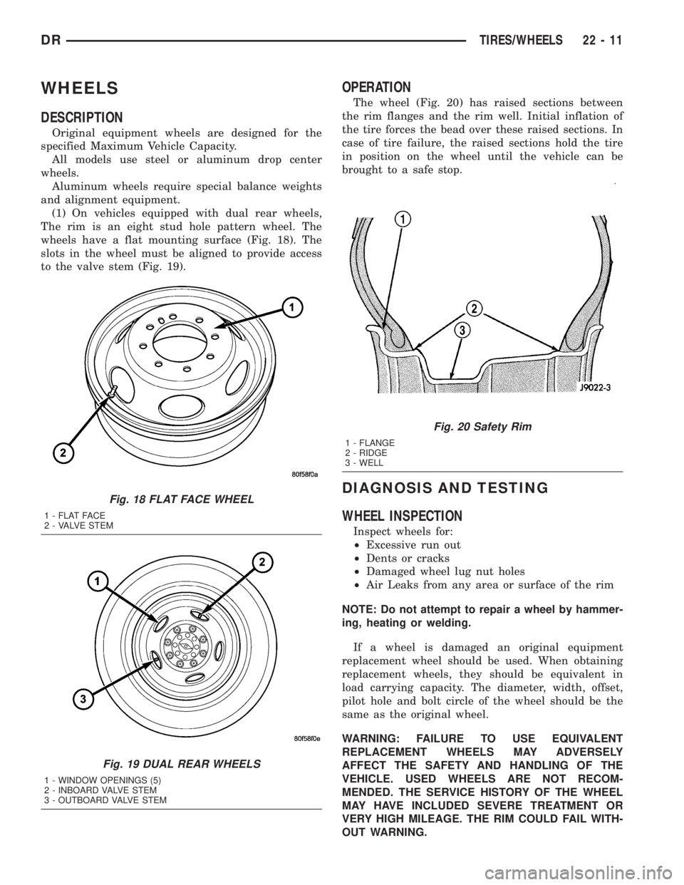
(1) Position converter clutch valve and 3-4 shift
valve springs in housing (Fig. 323).
(2) Loosely attach accumulator housing with right-
side screw (Fig. 323). Install only one screw at this
time as accumulator must be free to pivot upward for
ease of installation.
(3) Install 3-4 shift valve and spring.
(4) Install converter clutch timing valve and
spring.
(5) Position plug on end of converter clutch valve
spring. Then compress and hold springs and plug in
place with fingers of one hand.
(6) Swing accumulator housing upward over valve
springs and plug.
(7) Hold accumulator housing firmly in place and
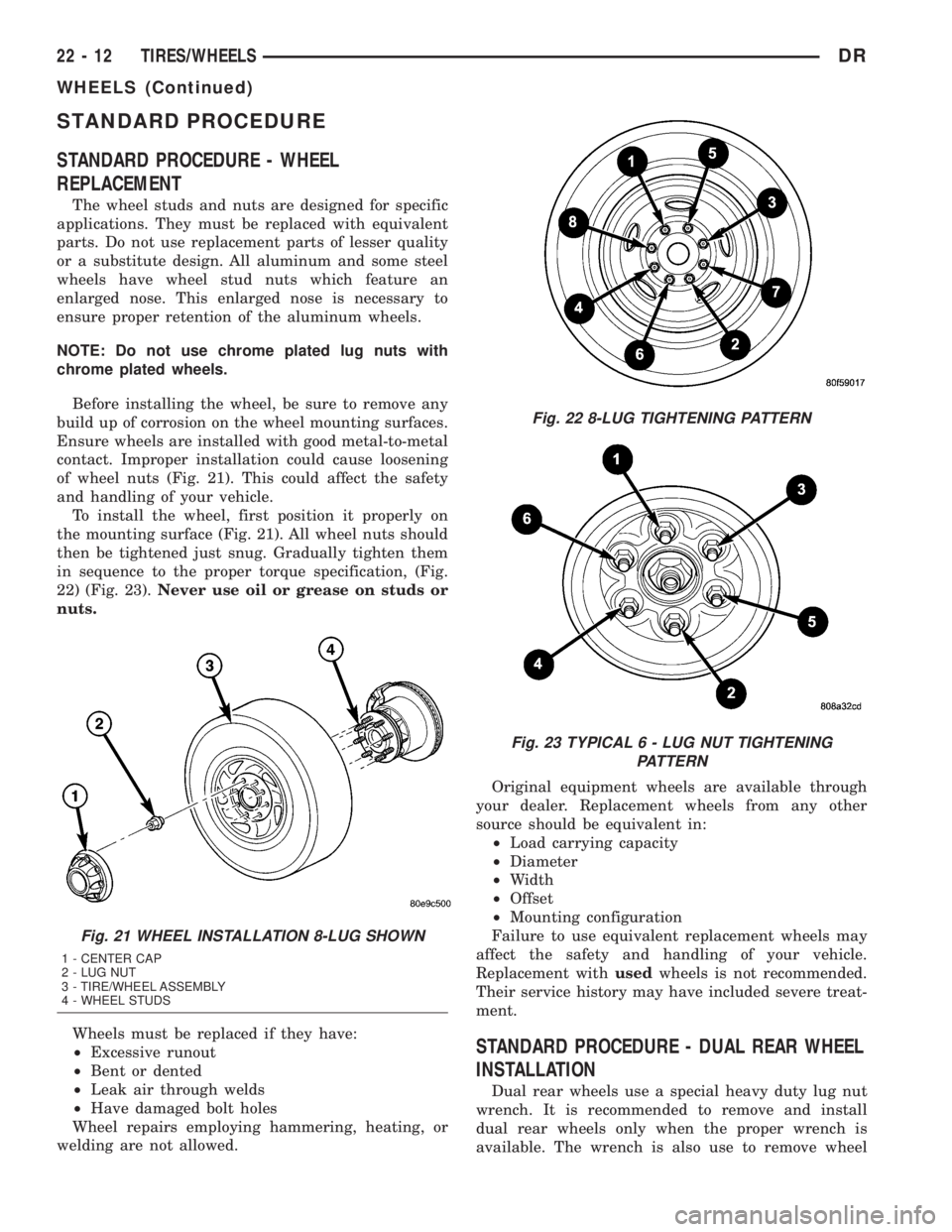
install remaining two attaching screws. Be sure
springs and clutch valve plug are properly seated
(Fig. 324). Tighten screws to 4 N´m (35 in. lbs.).
Fig. 322 Securing Boost Valve Tube With Brace
Tabs
1 - BEND TABS UP AGAINST TUBE AS SHOWN
Fig. 323 Converter Clutch And 3-4 Shift Valve
Springs
1 - RIGHT-SIDE SCREW
2 - 3-4 ACCUMULATOR
3 - 3-4 SHIFT VALVE SPRING
4 - CONVERTER CLUTCH VALVE SPRING
Fig. 324 Seating 3-4 Accumulator On Lower
Housing
1 - ACCUMULATOR BOX
2 - CONVERTER CLUTCH VALVE PLUG
21 - 484 AUTOMATIC TRANSMISSION - 48REDR
VALVE BODY (Continued)
Page 2570 of 2895

WHEELS
DESCRIPTION
Original equipment wheels are designed for the
specified Maximum Vehicle Capacity.
All models use steel or aluminum drop center
wheels.
Aluminum wheels require special balance weights
and alignment equipment.
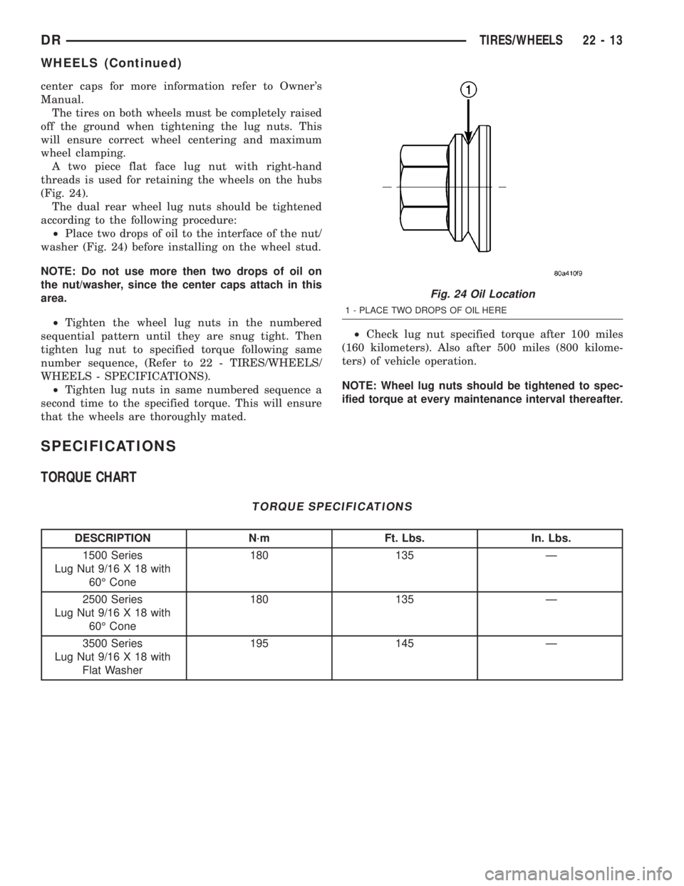
(1) On vehicles equipped with dual rear wheels,
The rim is an eight stud hole pattern wheel. The
wheels have a flat mounting surface (Fig. 18). The
slots in the wheel must be aligned to provide access
to the valve stem (Fig. 19).
OPERATION
The wheel (Fig. 20) has raised sections between
the rim flanges and the rim well. Initial inflation of
the tire forces the bead over these raised sections. In
case of tire failure, the raised sections hold the tire
in position on the wheel until the vehicle can be
brought to a safe stop.
DIAGNOSIS AND TESTING
WHEEL INSPECTION
Inspect wheels for:
²Excessive run out
²Dents or cracks
²Damaged wheel lug nut holes
²Air Leaks from any area or surface of the rim
NOTE: Do not attempt to repair a wheel by hammer-
ing, heating or welding.
If a wheel is damaged an original equipment
replacement wheel should be used. When obtaining
replacement wheels, they should be equivalent in
load carrying capacity. The diameter, width, offset,
pilot hole and bolt circle of the wheel should be the
same as the original wheel.
WARNING: FAILURE TO USE EQUIVALENT
REPLACEMENT WHEELS MAY ADVERSELY
AFFECT THE SAFETY AND HANDLING OF THE
VEHICLE. USED WHEELS ARE NOT RECOM-
MENDED. THE SERVICE HISTORY OF THE WHEEL
MAY HAVE INCLUDED SEVERE TREATMENT OR
VERY HIGH MILEAGE. THE RIM COULD FAIL WITH-
OUT WARNING.
Fig. 18 FLAT FACE WHEEL
1 - FLAT FACE
2 - VALVE STEM
Fig. 19 DUAL REAR WHEELS
1 - WINDOW OPENINGS (5)
2 - INBOARD VALVE STEM
3 - OUTBOARD VALVE STEM
Fig. 20 Safety Rim
1 - FLANGE
2 - RIDGE
3 - WELL
DRTIRES/WHEELS 22 - 11
Page 2571 of 2895

STANDARD PROCEDURE
STANDARD PROCEDURE - WHEEL
REPLACEMENT
The wheel studs and nuts are designed for specific
applications. They must be replaced with equivalent
parts. Do not use replacement parts of lesser quality
or a substitute design. All aluminum and some steel
wheels have wheel stud nuts which feature an
enlarged nose. This enlarged nose is necessary to
ensure proper retention of the aluminum wheels.
NOTE: Do not use chrome plated lug nuts with
chrome plated wheels.
Before installing the wheel, be sure to remove any
build up of corrosion on the wheel mounting surfaces.
Ensure wheels are installed with good metal-to-metal
contact. Improper installation could cause loosening
of wheel nuts (Fig. 21). This could affect the safety
and handling of your vehicle.
To install the wheel, first position it properly on
the mounting surface (Fig. 21). All wheel nuts should
then be tightened just snug. Gradually tighten them
in sequence to the proper torque specification, (Fig.
22) (Fig. 23).Never use oil or grease on studs or
nuts.
Wheels must be replaced if they have:
²Excessive runout
²Bent or dented
²Leak air through welds
²Have damaged bolt holes
Wheel repairs employing hammering, heating, or
welding are not allowed.Original equipment wheels are available through
your dealer. Replacement wheels from any other
source should be equivalent in:
²Load carrying capacity
²Diameter
²Width
²Offset
²Mounting configuration
Failure to use equivalent replacement wheels may
affect the safety and handling of your vehicle.
Replacement withusedwheels is not recommended.
Their service history may have included severe treat-
ment.
STANDARD PROCEDURE - DUAL REAR WHEEL
INSTALLATION
Dual rear wheels use a special heavy duty lug nut
wrench. It is recommended to remove and install
dual rear wheels only when the proper wrench is
available. The wrench is also use to remove wheel
Fig. 21 WHEEL INSTALLATION 8-LUG SHOWN
1 - CENTER CAP
2 - LUG NUT
3 - TIRE/WHEEL ASSEMBLY
4 - WHEEL STUDS
Fig. 22 8-LUG TIGHTENING PATTERN
Fig. 23 TYPICAL 6 - LUG NUT TIGHTENING
PATTERN
22 - 12 TIRES/WHEELSDR
WHEELS (Continued)
Page 2572 of 2895

center caps for more information refer to Owner's
Manual.
The tires on both wheels must be completely raised
off the ground when tightening the lug nuts. This
will ensure correct wheel centering and maximum
wheel clamping.
A two piece flat face lug nut with right-hand
threads is used for retaining the wheels on the hubs
(Fig. 24).
The dual rear wheel lug nuts should be tightened
according to the following procedure:
²Place two drops of oil to the interface of the nut/
washer (Fig. 24) before installing on the wheel stud.
NOTE: Do not use more then two drops of oil on
the nut/washer, since the center caps attach in this
area.
²Tighten the wheel lug nuts in the numbered
sequential pattern until they are snug tight. Then
tighten lug nut to specified torque following same
number sequence, (Refer to 22 - TIRES/WHEELS/
WHEELS - SPECIFICATIONS).
²Tighten lug nuts in same numbered sequence a
second time to the specified torque. This will ensure
that the wheels are thoroughly mated.²Check lug nut specified torque after 100 miles
(160 kilometers). Also after 500 miles (800 kilome-
ters) of vehicle operation.
NOTE: Wheel lug nuts should be tightened to spec-
ified torque at every maintenance interval thereafter.
SPECIFICATIONS
TORQUE CHART
TORQUE SPECIFICATIONS
DESCRIPTION N´m Ft. Lbs. In. Lbs.
1500 Series
Lug Nut 9/16 X 18 with
60É Cone180 135 Ð
2500 Series
Lug Nut 9/16 X 18 with
60É Cone180 135 Ð
3500 Series
Lug Nut 9/16 X 18 with
Flat Washer195 145 Ð
Fig. 24 Oil Location
1 - PLACE TWO DROPS OF OIL HERE
DRTIRES/WHEELS 22 - 13
WHEELS (Continued)