2003 DODGE RAM C1 connector
[x] Cancel search: C1 connectorPage 343 of 2895
Fan speed is monitored by the ECM. A lack of fan
speed will set a DTC. Circuit concerns will also set
fan clutch DTC's.
Fan speed and duty cycle percent can be monitored
with the DRB III..
DIAGNOSIS AND TESTING - ELECTRONICLY
CONTOLLED VISCOUS FAN DRIVE
NOISE
NOTE: It is normal for fan noise to be louder (roar-
ing) when:
²Fan duty cycle high. This may occur when ambi-
ent (outside air temperature) is very high.
²Engine loads and temperatures are high such as
when towing a trailer.
²Cool silicone fluid within the fan drive unit is
being redistributed back to its normal disengaged
(warm) position. This can occur during the first 15
seconds to one minute after engine start-up on a cold
engine.
LEAKS
Viscous fan drive operation is not affected by small
oil stains near the drive bearing. If leakage appears
excessive, replace the fan drive unit.
ELECTRONICALLY CONTROLLED VISCOUS DRIVE
If the fan assembly free-wheels without drag (the
fan blades will revolve more than five turns when
spun by hand), replace the fan drive. This spin test
must be performed when the engine is cool.
For the following test, the cooling system must be
in good condition. It also will ensure against exces-
sively high coolant temperature.
The Electronic Viscous Fan drive can be tested
using the DRB III scan tool.
(1) Set the parking brake and verify the transmis-
sion is in park or neutral.
(2) Stat and allow engine to reach normal operat-
ing termeratures.
(3) With engine idling, connect the DRB III and
select appropraite model year and engine option.
(4) Lacate and select actuator tests, then select
PWM Viscous Fan.
(5) Monitor fan speed and duty cycle; verify that
the fan speed increments are proportional to the duty
cycle precentage during the actuation event.
CAUTION: Some engines equipped with serpentine
drive belts have reverse rotating fans and viscous
fan drives. They are marked with the word
REVERSE to designate their usage. Installation of
the wrong fan or viscous fan drive can result in
engine overheating.
CAUTION: If the viscous fan drive is replaced
because of mechanical damage, the cooling fan
blades should also be inspected. Inspect for fatigue
cracks, loose blades, or loose rivets that could
have resulted from excessive vibration. Replace fan
blade assembly if any of these conditions are
found.
RADIATOR
DESCRIPTION
The radiator is a aluminum cross-flow design with
horizontal tubes through the radiator core and verti-
cal plastic side tanks (Fig. 32).
This radiator does not contain an internal trans-
mission oil cooler
OPERATION
The radiator supplies sufficient heat transfer using
the cooling fins interlaced between the horizontal
tubes in the radiator core to cool the engine.
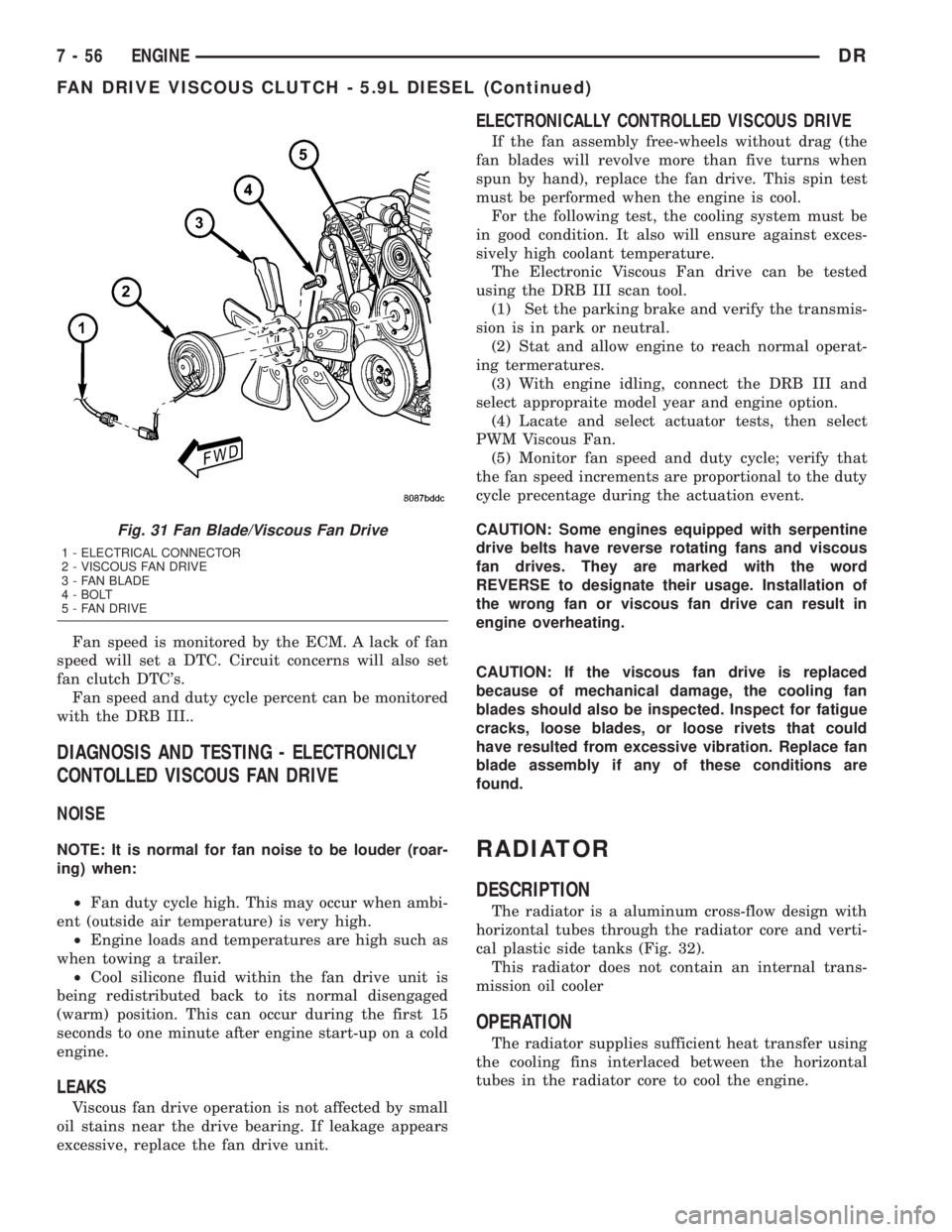
Fig. 31 Fan Blade/Viscous Fan Drive
1 - ELECTRICAL CONNECTOR
2 - VISCOUS FAN DRIVE
3 - FAN BLADE
4 - BOLT
5 - FAN DRIVE
7 - 56 ENGINEDR
FAN DRIVE VISCOUS CLUTCH - 5.9L DIESEL (Continued)
Page 344 of 2895

DIAGNOSIS AND TESTINGÐRADIATOR
COOLANT FLOW
Use the following procedure to determine if coolant
is flowing through the cooling system.
(1) Idle engine until operating temperature is
reached. If the upper radiator hose is warm to the
touch, the thermostat is opening and coolant is flow-
ing to the radiator.
WARNING: HOT, PRESSURIZED COOLANT CAN
CAUSE INJURY BY SCALDING. USING A RAG TO
COVER THE RADIATOR PRESSURE CAP, OPEN
RADIATOR CAP SLOWLY TO THE FIRST STOP. THIS
WILL ALLOW ANY BUILT-UP PRESSURE TO VENT
TO THE RESERVE/OVERFLOW TANK. AFTER PRES-
SURE BUILD-UP HAS BEEN RELEASED, REMOVE
CAP FROM FILLER NECK.
(2) Drain a small amount of coolant from the radi-
ator until the ends of the radiator tubes are visible
through the filler neck. Idle the engine at normal
operating temperature. If coolant is flowing past the
exposed tubes, the coolant is circulating.
REMOVAL
(1) Disconnect battery negative cables.WARNING: DO NOT REMOVE THE CYLINDER
BLOCK DRAIN PLUGS OR LOOSEN THE RADIATOR
DRAINCOCK WITH THE SYSTEM HOT AND UNDER
PRESSURE. SERIOUS BURNS FROM THE COOL-
ANT CAN OCCUR.
(2) Drain the cooling system (Refer to 7 - COOL-
ING - STANDARD PROCEDURE).
WARNING: CONSTANT TENSION HOSE CLAMPS
ARE USED ON MOST COOLING SYSTEM HOSES.
WHEN REMOVING OR INSTALLING, USE ONLY
TOOLS DESIGNED FOR SERVICING THIS TYPE OF
CLAMP. ALWAYS WEAR SAFETY GLASSES WHEN
SERVICING CONSTANT TENSION CLAMPS.
CAUTION: A number or letter is stamped into the
tongue of constant tension clamps. If replacement
is necessary, use only an original equipment clamp
with a matching number or letter and the correct
width.
(3) Remove the hose clamps and hoses from radia-
tor.
(4) Remove the coolant reserve/overflow tank hose
from the radiator filler neck.
(5) Remove the coolant reserve/overflow tank
(5.9L) or the coolant degas container(3.7L/4.7L) from
the fan shroud (pull straight up). The tank slips into
slots on the fan shroud.
(6) Unclip the power steering hoses from the fan
shroud.
(7) Disconnect the electrical connectors at the
windshield washer reservoir tank and remove the
tank.
(8) Remove the fan shroud mounting bolts and pull
up and out of the radiator tank clips (Fig. 33). Posi-
tion shroud rearward over the fan blades towards
engine.
(9) Disconnect the transmission cooler lines from
the transmission cooler, then plug the transmission
lines and cooler to prevent leakage.
(10) Disconnect the power steering lines from the
power steering cooler, then plug the power steering
lines and cooler to prevent leakage.
(11) Remove the two radiator upper mounting
bolts (Fig. 34).
(12) Lift the radiator straight up and out of the
engine compartment. Take care not to damage cool-
ing fins or tubes on the radiator and oil coolers when
removing.
Fig. 32 Radiator Ð Typical
1 - SCREW
2 - SCREW
3 - LOWER MOUNT
4 - RADIATOR
5 - DRAINCOCK
6 -LOWER MOUNT
DRENGINE 7 - 57
RADIATOR (Continued)
Page 345 of 2895
NOTE: The radiator is equipped with one alignment
dowel on the bottom of the outlet tank and one
retaining bracket on the front side of the inlet tank.
Both features have rubber insulators attached to
them that must be present. The alignment dowel fits
into a hole at the bottom of the front end sheet
metal vertical support post and the support bracket
rests on top of the lower radiator closure tube.
CLEANING
Clean radiator fins are necessary for good heat
transfer. The radiator and oil cooler fins should be
cleaned when an accumulation of debris has
occurred. With the engine cold, apply cold water and
compressed air to the back (engine side) of the radi-
ator to flush the radiator and/or oil coolers of debris.
INSPECTION
Inspect the radiator side tanks for cracks, broken
or missing fittings also inspect the joint where the
tanks seam up to the radiator core for signs of leak-
age and/or deteriorating seals.
Inspect radiator core for corroded, bent or missing
cooling fins. Inspect the core for bent or damaged
cooling tubes.
INSTALLATION
(1) Position the fan shroud over the fan blades
rearward towards engine.
(2) Install the rubber insulators to the lower radi-
ator mounting features (alignment dowel and support
bracket at the lower part of the radiator).
(3) Lower the radiator into position while guiding
the alignment dowel into the vertical post bracket.
Position and seat the lower radiator support bracket
onto the lower radiator closure tube.
(4) Install the upper radiator mounting bolts.
Tighten bolts to 8.5 N´m (75 in. lbs.).
(5) Connect the lower radiator hose and install the
clamp in the proper position.
(6) Connect the power steering hoses to the power
steering oil cooler and install the clamps.
(7) Connect the transmission oil cooler lines to the
transmission oil cooler and install the secondary
latches.
(8) Position the fan shroud into the mounting clips
on the radiator tanks and secure with bolts. Tighten
the bolts to 8.5 N´m (75 in. lbs.).
(9) Secure the power steering hoses into the clip
on the lower fan shroud.
(10) Install the windshield washer reservoir tank
and connect the hose and electrical connector.
(11) Install coolant reserve/overflow container
hose(s) to radiator filler neck and secure properly
with clamps.
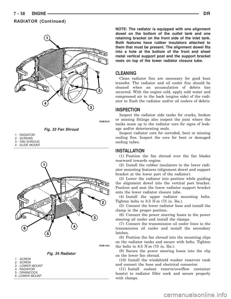
Fig. 33 Fan Shroud
1 - RADIATOR
2 - SCREWS
3 - FAN SHROUD
4 - SLIDE MOUNT
Fig. 34 Radiator
1 - SCREW
2 - SCREW
3 - LOWER MOUNT
4 - RADIATOR
5 - DRAINCOCK
6 -LOWER MOUNT
7 - 58 ENGINEDR
RADIATOR (Continued)
Page 364 of 2895

AUDIO
TABLE OF CONTENTS
page page
AUDIO
DESCRIPTION..........................1
OPERATION............................1
DIAGNOSIS AND TESTING - AUDIO..........2
AMPLIFIER
DESCRIPTION..........................3
OPERATION............................3
REMOVAL.............................3
INSTALLATION..........................4
ANTENNA BODY & CABLE
DESCRIPTION..........................4
OPERATION............................4
DIAGNOSIS AND TESTING - ANTENNA BODY
AND CABLE..........................4
REMOVAL.............................6
INSTALLATION..........................6
INSTRUMENT PANEL ANTENNA CABLE
REMOVAL.............................6
INSTALLATION..........................7
RADIO
DESCRIPTION..........................7OPERATION............................7
REMOVAL.............................7
INSTALLATION..........................8
RADIO NOISE SUPPRESSION GROUND STRAP
DESCRIPTION..........................8
OPERATION............................8
REMOVAL.............................9
INSTALLATION.........................10
REMOTE SWITCHES
DESCRIPTION.........................10
OPERATION...........................10
DIAGNOSIS AND TESTING - REMOTE
SWITCHES..........................11
REMOVAL.............................12
INSTALLATION.........................12
SPEAKER
DESCRIPTION.........................12
OPERATION...........................12
DIAGNOSIS AND TESTING - SPEAKER......13
REMOVAL.............................13
INSTALLATION.........................15
AUDIO
DESCRIPTION
An audio system is standard factory-installed
equipment on this model. Several combinations of
radio receivers and speaker systems are offered. The
audio system uses an ignition switched source of bat-
tery current so that the system will only operate
when the ignition switch is in the RUN or ACCES-
SORY positions.
The audio system includes the following compo-
nents:
²Antenna
²Power amplifier (with premium speaker system
only)
²Radio noise suppression components
²Radio receiver
²Remote radio switches (if equipped)
²Speakers
Certain functions and features of the audio system
rely upon resources shared with other electronic
modules in the vehicle over the Programmable Com-
munication Interface (PCI) bus network. The data
bus network allows the sharing of sensor informa-
tion. For diagnosis of these electronic modules or of
the data bus network, the use of a DRB IIItscan tooland the proper Diagnostic Procedures manual are
recommended.
Refer to the appropriate wiring information for
complete standard and premium audio system circuit
diagrams. The wiring information includes proper
wire and connector repair procedures, further details
on wire harness routing and retention, as well as
pin-out and location views for the various wire har-
ness connectors, splices, and grounds.
OPERATION
The audio system components are designed to pro-
vide audio entertainment and information through
the reception, tuning and amplification of locally
broadcast radio signals in both the Amplitude Modu-
lating (AM) and Frequency Modulating (FM) com-
mercial frequency ranges.
The audio system components operate on battery
current received through a fuse in the Integrated
Power Module (IPM) on a fused ignition switch out-
put (run-acc) circuit so that the system will only
operate when the ignition switch is in the Run or
Accessory positions.
On vehicles that are equipped with the optional
remote radio switches, the Instrument Cluster
receives hard wired resistor multiplexed inputs from
the remote radio switches. The programming in the
DRAUDIO 8A - 1
Page 365 of 2895

Instrument Cluster allows it to process those inputs
and send the proper messages to the radio receiver
over the Programmable Communication Interface
(PCI) bus network to control the radio volume up or
down, station seek up or down, preset station
advance, and mode advance functions.
Refer to the owner's manual for more information
on the features, use and operation of each of the
available audio systems.
DIAGNOSIS AND TESTING - AUDIO
Any diagnosis of the Audio system should
begin with the use of the DRB IIItdiagnostic
tool. For information on the use of the DRB
IIIt, refer to the appropriate Diagnostic Service
Manual.
Refer to the appropriate wiring information. The
wiring information includes wiring diagrams, proper
wire and connector repair procedures, details of wireharness routing and retention, connector pin-out
information and location views for the various wire
harness connectors, splices and grounds.
WARNING: DISABLE THE AIRBAG SYSTEM
BEFORE ATTEMPTING ANY STEERING WHEEL,
STEERING COLUMN, SEAT BELT TENSIONER, SIDE
AIRBAG, OR INSTRUMENT PANEL COMPONENT
DIAGNOSIS OR SERVICE. DISCONNECT AND ISO-
LATE THE BATTERY NEGATIVE (GROUND) CABLE,
THEN WAIT TWO MINUTES FOR THE AIRBAG SYS-
TEM CAPACITOR TO DISCHARGE BEFORE PER-
FORMING FURTHER DIAGNOSIS OR SERVICE. THIS
IS THE ONLY SURE WAY TO DISABLE THE AIRBAG
SYSTEM. FAILURE TO TAKE THE PROPER PRE-
CAUTIONS COULD RESULT IN ACCIDENTAL AIR-
BAG DEPLOYMENT AND POSSIBLE PERSONAL
INJURY.
AUDIO SYSTEM DIAGNOSIS TABLE
CONDITION POSSIBLE CAUSES CORRECTION
NO AUDIO 1. Fuse faulty. 1. Check radio fuse and Ignition-Off Draw (IOD)
fuse in the Integrated Power Module (IPM).
Replace fuses, if required.
2. Radio/amplifier (if
equipped) connector faulty.2. Check for loose or corroded radio/amplifier
connector. Repair, if required.
3. Wiring faulty. 3. Check for shorted or open wires. Repair wiring,
if required.
4. Radio/amplifier (if
equipped) ground faulty.4. Check for continuity between radio chassis and
a known good ground. There should be
continuity. Repair ground, if required.
5. Radio/amplifier (if
equipped) faulty.5. Refer to appropriate Diagnostic Service
Manual.
6. Speakers faulty. 6. Replace speaker as necessary.
NO RADIO DISPLAY 1. Fuse faulty. 1. Check radio fuse and Ignition-Off Draw (IOD)
fuse in Integrated Power Module (IPM). Replace
fuses, if required.
2. Radio connector faulty. 2. Check for loose or corroded radio connector.
Repair, if required.
3. Wiring faulty. 3. Check for battery voltage at radio connector.
Repair wiring, if required.
4. Radio ground faulty. 4. Check for continuity between radio chassis and
a known good ground. There should be
continuity. Repair ground, if required.
5. Radio faulty. 5. Refer to appropriate Diagnostic Service
Manual.
8A - 2 AUDIODR
AUDIO (Continued)
Page 366 of 2895

CONDITION POSSIBLE CAUSES CORRECTION
CLOCK WILL NOT KEEP
SET TIME1. Fuse faulty. 1. Check Ignition-Off Draw (IOD) fuse in the
Integrated Power Module (IPM). Replace fuse, if
required.
2. Radio connector faulty. 2. Check for loose or corroded radio connector.
Repair, if required.
3. Wiring faulty. 3. Check for battery voltage at radio connector.
Repair wiring, if required.
4. Radio ground faulty. 4. Check for continuity between radio chassis and
a known good ground. There should be
continuity. Repair ground, if required.
5. Radio faulty. 5. Refer to appropriate Diagnostic Service
Manual.
POOR RADIO RECEPTION 1. Antenna faulty. 1. (Refer to 8 - ELECTRICAL/AUDIO/ANTENNA
BODY & CABLE - DIAGNOSIS AND TESTING).
2. Radio ground faulty. 2. Check for continuity between radio chassis and
a known good ground. There should be
continuity. Repair ground, if required.
3. Radio noise suppression
faulty.3. Repair or replace ground strap as necessary.
4. Radio faulty. 4. Refer to appropriate Diagnostic Service
Manual.
NO/POOR TAPE
OPERATION1. Faulty tape. 1. Insert known good tape and test operation.
2. Foreign objects behind
tape door.2. Remove foreign objects and test operation.
3. Dirty cassette tape head. 3. Clean head with Mopar Cassette Head
Cleaner.
4. Faulty tape deck. 4. Exchange or replace radio, if required.
NO COMPACT DISC
OPERATION1. Faulty CD. 1. Insert known good CD and test operation.
2. Foreign material on CD. 2. Clean CD and test operation.
3. Condensation on CD or
optics.3. Allow temperature of vehicle interior to stabilize
and test operation.
4. Faulty CD player. 4. Refer to appropriate Diagnostic Service
Manual.
AMPLIFIER
DESCRIPTION
The optional Infinity premium speaker system
includes a separate Infinity audio power amplifier.
The amplifier is a six channel unit and is rated at
240 total output watts. The amplifier is located
behind the glove box.
OPERATION
The power amplifier electronically increases the
frequency response of the normal audio signal output
from the radio amplifier in order to improve the
acoustic performance of the speakers. On vehiclesequipped with an amplifier, the amplifier section of
the radio becomes a pre-amplifier.
The amplifier receives audio signal inputs for
speaker channels from the radio, then sends ampli-
fied audio outputs through six separate channels
with dedicated feed and return circuits to the indi-
vidual speakers.
REMOVAL
(1) Disconnect and isolate the battery negative
cable.
(2) Remove glove box (Refer to 23 - BODY/IN-
STRUMENT PANEL/GLOVE BOX - REMOVAL).
DRAUDIO 8A - 3
AUDIO (Continued)
Page 367 of 2895
(3) Remove instrument panel center bezel (Refer to
23 - BODY/INSTRUMENT PANEL/INSTRUMENT
PANEL CENTER BEZEL - REMOVAL).
(4) Remove instrument panel lower right center
bezel (Refer to 23 - BODY/INSTRUMENT PANEL/IP
LOWER RIGHT CENTER BEZEL - REMOVAL).
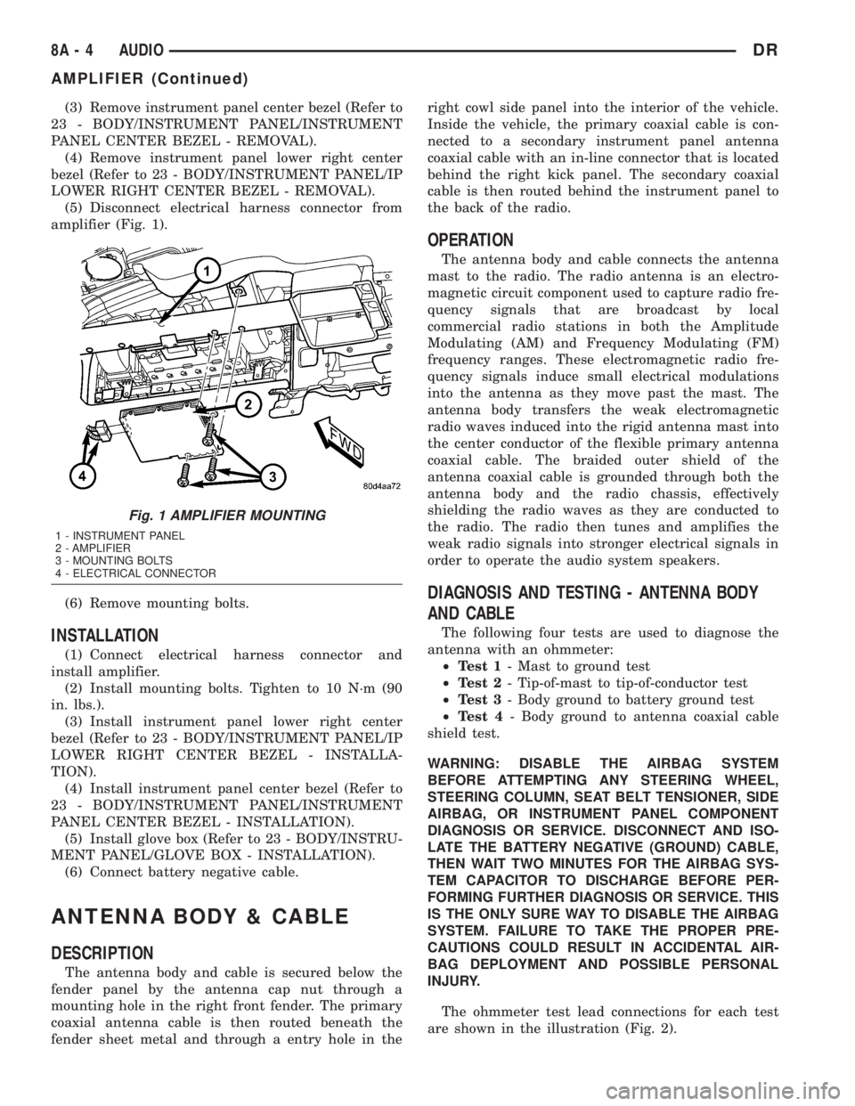
(5) Disconnect electrical harness connector from
amplifier (Fig. 1).
(6) Remove mounting bolts.
INSTALLATION
(1) Connect electrical harness connector and
install amplifier.
(2) Install mounting bolts. Tighten to 10 N´m (90
in. lbs.).
(3) Install instrument panel lower right center
bezel (Refer to 23 - BODY/INSTRUMENT PANEL/IP
LOWER RIGHT CENTER BEZEL - INSTALLA-
TION).
(4) Install instrument panel center bezel (Refer to
23 - BODY/INSTRUMENT PANEL/INSTRUMENT
PANEL CENTER BEZEL - INSTALLATION).
(5) Install glove box (Refer to 23 - BODY/INSTRU-
MENT PANEL/GLOVE BOX - INSTALLATION).
(6) Connect battery negative cable.
ANTENNA BODY & CABLE
DESCRIPTION
The antenna body and cable is secured below the
fender panel by the antenna cap nut through a
mounting hole in the right front fender. The primary
coaxial antenna cable is then routed beneath the
fender sheet metal and through a entry hole in theright cowl side panel into the interior of the vehicle.
Inside the vehicle, the primary coaxial cable is con-
nected to a secondary instrument panel antenna
coaxial cable with an in-line connector that is located
behind the right kick panel. The secondary coaxial
cable is then routed behind the instrument panel to
the back of the radio.
OPERATION
The antenna body and cable connects the antenna
mast to the radio. The radio antenna is an electro-
magnetic circuit component used to capture radio fre-
quency signals that are broadcast by local
commercial radio stations in both the Amplitude
Modulating (AM) and Frequency Modulating (FM)
frequency ranges. These electromagnetic radio fre-
quency signals induce small electrical modulations
into the antenna as they move past the mast. The
antenna body transfers the weak electromagnetic
radio waves induced into the rigid antenna mast into
the center conductor of the flexible primary antenna
coaxial cable. The braided outer shield of the
antenna coaxial cable is grounded through both the
antenna body and the radio chassis, effectively
shielding the radio waves as they are conducted to
the radio. The radio then tunes and amplifies the
weak radio signals into stronger electrical signals in
order to operate the audio system speakers.
DIAGNOSIS AND TESTING - ANTENNA BODY
AND CABLE
The following four tests are used to diagnose the
antenna with an ohmmeter:
²Test 1- Mast to ground test
²Test 2- Tip-of-mast to tip-of-conductor test
²Test 3- Body ground to battery ground test
²Test 4- Body ground to antenna coaxial cable
shield test.
WARNING: DISABLE THE AIRBAG SYSTEM
BEFORE ATTEMPTING ANY STEERING WHEEL,
STEERING COLUMN, SEAT BELT TENSIONER, SIDE
AIRBAG, OR INSTRUMENT PANEL COMPONENT
DIAGNOSIS OR SERVICE. DISCONNECT AND ISO-
LATE THE BATTERY NEGATIVE (GROUND) CABLE,
THEN WAIT TWO MINUTES FOR THE AIRBAG SYS-
TEM CAPACITOR TO DISCHARGE BEFORE PER-
FORMING FURTHER DIAGNOSIS OR SERVICE. THIS
IS THE ONLY SURE WAY TO DISABLE THE AIRBAG
SYSTEM. FAILURE TO TAKE THE PROPER PRE-
CAUTIONS COULD RESULT IN ACCIDENTAL AIR-
BAG DEPLOYMENT AND POSSIBLE PERSONAL
INJURY.
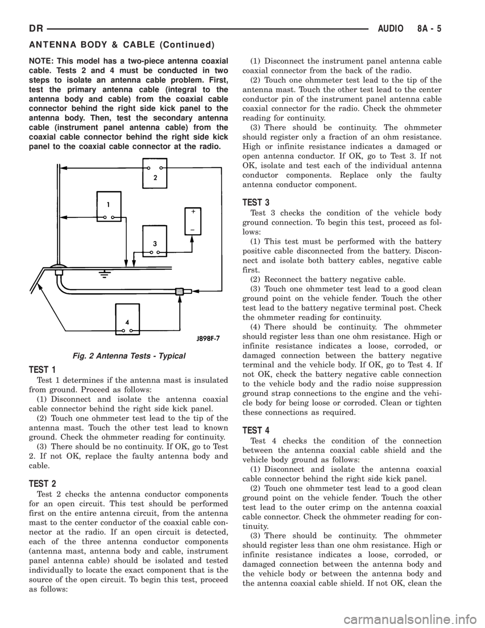
The ohmmeter test lead connections for each test
are shown in the illustration (Fig. 2).
Fig. 1 AMPLIFIER MOUNTING
1 - INSTRUMENT PANEL
2 - AMPLIFIER
3 - MOUNTING BOLTS
4 - ELECTRICAL CONNECTOR
8A - 4 AUDIODR
AMPLIFIER (Continued)
Page 368 of 2895
NOTE: This model has a two-piece antenna coaxial
cable. Tests 2 and 4 must be conducted in two
steps to isolate an antenna cable problem. First,
test the primary antenna cable (integral to the
antenna body and cable) from the coaxial cable
connector behind the right side kick panel to the
antenna body. Then, test the secondary antenna
cable (instrument panel antenna cable) from the
coaxial cable connector behind the right side kick
panel to the coaxial cable connector at the radio.
TEST 1
Test 1 determines if the antenna mast is insulated
from ground. Proceed as follows:
(1) Disconnect and isolate the antenna coaxial
cable connector behind the right side kick panel.
(2) Touch one ohmmeter test lead to the tip of the
antenna mast. Touch the other test lead to known
ground. Check the ohmmeter reading for continuity.
(3) There should be no continuity. If OK, go to Test
2. If not OK, replace the faulty antenna body and
cable.
TEST 2
Test 2 checks the antenna conductor components
for an open circuit. This test should be performed
first on the entire antenna circuit, from the antenna
mast to the center conductor of the coaxial cable con-
nector at the radio. If an open circuit is detected,
each of the three antenna conductor components
(antenna mast, antenna body and cable, instrument
panel antenna cable) should be isolated and tested
individually to locate the exact component that is the
source of the open circuit. To begin this test, proceed
as follows:(1) Disconnect the instrument panel antenna cable
coaxial connector from the back of the radio.
(2) Touch one ohmmeter test lead to the tip of the
antenna mast. Touch the other test lead to the center
conductor pin of the instrument panel antenna cable
coaxial connector for the radio. Check the ohmmeter
reading for continuity.
(3) There should be continuity. The ohmmeter
should register only a fraction of an ohm resistance.
High or infinite resistance indicates a damaged or
open antenna conductor. If OK, go to Test 3. If not
OK, isolate and test each of the individual antenna
conductor components. Replace only the faulty
antenna conductor component.
TEST 3
Test 3 checks the condition of the vehicle body
ground connection. To begin this test, proceed as fol-
lows:
(1) This test must be performed with the battery
positive cable disconnected from the battery. Discon-
nect and isolate both battery cables, negative cable
first.
(2) Reconnect the battery negative cable.
(3) Touch one ohmmeter test lead to a good clean
ground point on the vehicle fender. Touch the other
test lead to the battery negative terminal post. Check
the ohmmeter reading for continuity.
(4) There should be continuity. The ohmmeter
should register less than one ohm resistance. High or
infinite resistance indicates a loose, corroded, or
damaged connection between the battery negative
terminal and the vehicle body. If OK, go to Test 4. If
not OK, check the battery negative cable connection
to the vehicle body and the radio noise suppression
ground strap connections to the engine and the vehi-
cle body for being loose or corroded. Clean or tighten
these connections as required.
TEST 4
Test 4 checks the condition of the connection
between the antenna coaxial cable shield and the
vehicle body ground as follows:
(1) Disconnect and isolate the antenna coaxial
cable connector behind the right side kick panel.
(2) Touch one ohmmeter test lead to a good clean
ground point on the vehicle fender. Touch the other
test lead to the outer crimp on the antenna coaxial
cable connector. Check the ohmmeter reading for con-
tinuity.
(3) There should be continuity. The ohmmeter
should register less than one ohm resistance. High or
infinite resistance indicates a loose, corroded, or
damaged connection between the antenna body and
the vehicle body or between the antenna body and
the antenna coaxial cable shield. If not OK, clean the
Fig. 2 Antenna Tests - Typical
DRAUDIO 8A - 5
ANTENNA BODY & CABLE (Continued)