2003 DODGE RAM sensor
[x] Cancel search: sensorPage 1705 of 2895
INSTALLATION
(1) Connect necessary wiring into electrical con-
nectors. Connect 4±wire electrical connector to pump
module.
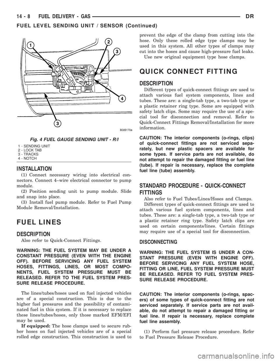
(2) Position sending unit to pump module. Slide
and snap into place.
(3) Install fuel pump module. Refer to Fuel Pump
Module Removal/Installation.
FUEL LINES
DESCRIPTION
Also refer to Quick-Connect Fittings.
WARNING: THE FUEL SYSTEM MAY BE UNDER A
CONSTANT PRESSURE (EVEN WITH THE ENGINE
OFF). BEFORE SERVICING ANY FUEL SYSTEM
HOSES, FITTINGS, LINES, OR MOST COMPO-
NENTS, FUEL SYSTEM PRESSURE MUST BE
RELEASED. REFER TO THE FUEL SYSTEM PRES-
SURE RELEASE PROCEDURE.
The lines/tubes/hoses used on fuel injected vehicles
are of a special construction. This is due to the
higher fuel pressures and the possibility of contami-
nated fuel in this system. If it is necessary to replace
these lines/tubes/hoses, only those marked EFM/EFI
may be used.
If equipped:The hose clamps used to secure rub-
ber hoses on fuel injected vehicles are of a special
rolled edge construction. This construction is used toprevent the edge of the clamp from cutting into the
hose. Only these rolled edge type clamps may be
used in this system. All other types of clamps may
cut into the hoses and cause high-pressure fuel leaks.
Use new original equipment type hose clamps.
QUICK CONNECT FITTING
DESCRIPTION
Different types of quick-connect fittings are used to
attach various fuel system components, lines and
tubes. These are: a single-tab type, a two-tab type or
a plastic retainer ring type. Some are equipped with
safety latch clips. Some may require the use of a spe-
cial tool for disconnection and removal. Refer to
Quick-Connect Fittings Removal/Installation for more
information.
CAUTION: The interior components (o-rings, clips)
of quick-connect fittings are not serviced sepa-
rately, but new plastic spacers are available for
some types. If service parts are not available, do
not attempt to repair the damaged fitting or fuel line
(tube). If repair is necessary, replace the complete
fuel line (tube) assembly.
STANDARD PROCEDURE - QUICK-CONNECT
FITTINGS
Also refer to Fuel Tubes/Lines/Hoses and Clamps.
Different types of quick-connect fittings are used to
attach various fuel system components, lines and
tubes. These are: a single-tab type, a two-tab type or
a plastic retainer ring type. Safety latch clips are
used on certain components/lines. Certain fittings
may require use of a special tool for disconnection.
DISCONNECTING
WARNING: THE FUEL SYSTEM IS UNDER A CON-
STANT PRESSURE (EVEN WITH ENGINE OFF).
BEFORE SERVICING ANY FUEL SYSTEM HOSE,
FITTING OR LINE, FUEL SYSTEM PRESSURE MUST
BE RELEASED. REFER TO FUEL SYSTEM PRES-
SURE RELEASE PROCEDURE.
CAUTION: The interior components (o-rings, spac-
ers) of some types of quick-connect fitting are not
serviced separately. If service parts are not avail-
able, do not attempt to repair a damaged fitting or
fuel line. If repair is necessary, replace complete
fuel line assembly.
(1) Perform fuel pressure release procedure. Refer
to Fuel Pressure Release Procedure.
Fig. 4 FUEL GAUGE SENDING UNIT - R/I
1 - SENDING UNIT
2 - LOCK TAB
3 - TRACKS
4 - NOTCH
14 - 8 FUEL DELIVERY - GASDR
FUEL LEVEL SENDING UNIT / SENSOR (Continued)
Page 1709 of 2895
FUEL PUMP
DESCRIPTION
The electric fuel pump is located inside of the fuel
pump module. A 12 volt, permanent magnet, electric
motor powers the fuel pump. The electric fuel pump
is not a separate, serviceable component.
OPERATION
Voltage to operate the electric pump is supplied
through the fuel pump relay.
Fuel is drawn in through a filter at the bottom of
the module and pushed through the electric motor
gearset to the pump outlet.
Check Valve Operation:The bottom section of
the fuel pump module contains a one-way check
valve to prevent fuel flow back into the tank and to
maintain fuel supply line pressure (engine warm)
when pump is not operational. It is also used to keep
the fuel supply line full of gasoline when pump is not
operational. After the vehicle has cooled down, fuel
pressure may drop to 0 psi (cold fluid contracts), but
liquid gasoline will remain in fuel supply line
between the check valve and fuel injectors.Fuel
pressure that has dropped to 0 psi on a cooled
down vehicle (engine off) is a normal condition.
The electric fuel pump is not a separate, service-
able component.
FUEL PUMP MODULE
DESCRIPTION
The fuel pump module assembly is located on the
top of the fuel tank (Fig. 1). The complete assembly
contains the following components:
²A combination fuel filter/fuel pressure regulator
²A separate fuel pick-up, or inlet filter
²An electric fuel pump
²A lockring to retain pump module to tank
²A soft gasket between tank flange and module
²A fuel gauge sending unit (fuel level sensor)
²Fuel line connection
The fuel gauge sending unit may be serviced sepa-
rately. If the electrical fuel pump, primary inlet filter,
fuel filter or fuel pressure regulator require service,
the fuel pump module must be replaced.
OPERATION
Refer to Fuel Pump, Inlet Filter, Fuel Filter / Fuel
Pressure Regulator and Fuel Gauge Sending Unit.
REMOVAL
WARNING: THE FUEL SYSTEM IS UNDER A CON-
STANT PRESSURE (EVEN WITH THE ENGINE OFF).BEFORE SERVICING THE FUEL PUMP MODULE, THE
FUEL SYSTEM PRESSURE MUST BE RELEASED.
(1) Drain and remove fuel tank. Refer to Fuel
Tank Removal/Installation.
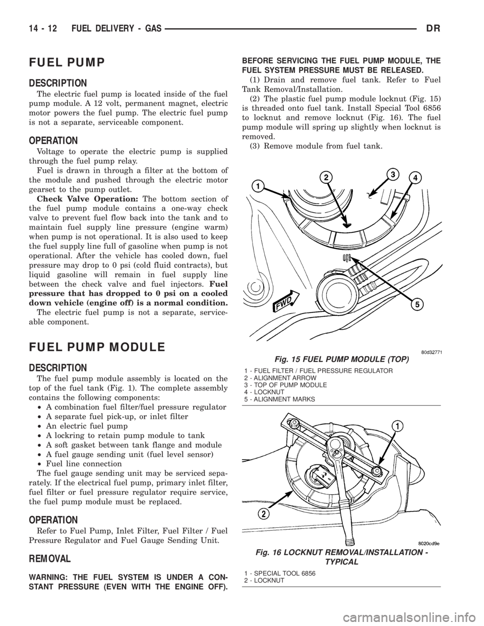
(2) The plastic fuel pump module locknut (Fig. 15)
is threaded onto fuel tank. Install Special Tool 6856
to locknut and remove locknut (Fig. 16). The fuel
pump module will spring up slightly when locknut is
removed.
(3) Remove module from fuel tank.
Fig. 15 FUEL PUMP MODULE (TOP)
1 - FUEL FILTER / FUEL PRESSURE REGULATOR
2 - ALIGNMENT ARROW
3 - TOP OF PUMP MODULE
4 - LOCKNUT
5 - ALIGNMENT MARKS
Fig. 16 LOCKNUT REMOVAL/INSTALLATION -
TYPICAL
1 - SPECIAL TOOL 6856
2 - LOCKNUT
14 - 12 FUEL DELIVERY - GASDR
Page 1710 of 2895
INSTALLATION
CAUTION: Whenever the fuel pump module is ser-
viced, the rubber gasket must be replaced.
(1) Using a new gasket, position fuel pump module
into opening in fuel tank.
(2) Position locknut over top of fuel pump module.
Install locknut finger tight.
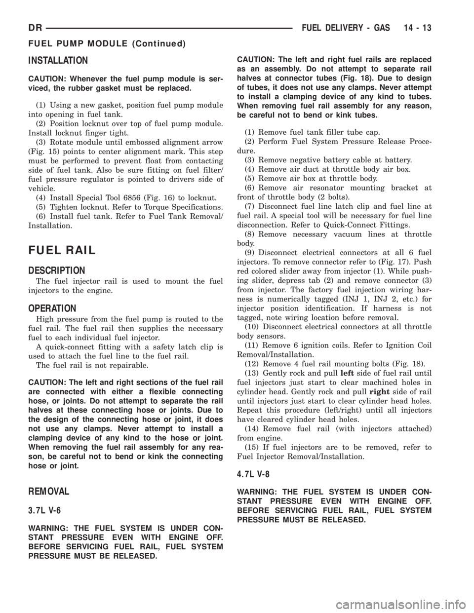
(3) Rotate module until embossed alignment arrow
(Fig. 15) points to center alignment mark. This step
must be performed to prevent float from contacting
side of fuel tank. Also be sure fitting on fuel filter/
fuel pressure regulator is pointed to drivers side of
vehicle.
(4) Install Special Tool 6856 (Fig. 16) to locknut.
(5) Tighten locknut. Refer to Torque Specifications.
(6) Install fuel tank. Refer to Fuel Tank Removal/
Installation.
FUEL RAIL
DESCRIPTION
The fuel injector rail is used to mount the fuel
injectors to the engine.
OPERATION
High pressure from the fuel pump is routed to the
fuel rail. The fuel rail then supplies the necessary
fuel to each individual fuel injector.
A quick-connect fitting with a safety latch clip is
used to attach the fuel line to the fuel rail.
The fuel rail is not repairable.
CAUTION: The left and right sections of the fuel rail
are connected with either a flexible connecting
hose, or joints. Do not attempt to separate the rail
halves at these connecting hose or joints. Due to
the design of the connecting hose or joint, it does
not use any clamps. Never attempt to install a
clamping device of any kind to the hose or joint.
When removing the fuel rail assembly for any rea-
son, be careful not to bend or kink the connecting
hose or joint.
REMOVAL
3.7L V-6
WARNING: THE FUEL SYSTEM IS UNDER CON-
STANT PRESSURE EVEN WITH ENGINE OFF.
BEFORE SERVICING FUEL RAIL, FUEL SYSTEM
PRESSURE MUST BE RELEASED.CAUTION: The left and right fuel rails are replaced
as an assembly. Do not attempt to separate rail
halves at connector tubes (Fig. 18). Due to design
of tubes, it does not use any clamps. Never attempt
to install a clamping device of any kind to tubes.
When removing fuel rail assembly for any reason,
be careful not to bend or kink tubes.
(1) Remove fuel tank filler tube cap.
(2) Perform Fuel System Pressure Release Proce-
dure.
(3) Remove negative battery cable at battery.
(4) Remove air duct at throttle body air box.
(5) Remove air box at throttle body.
(6) Remove air resonator mounting bracket at
front of throttle body (2 bolts).
(7) Disconnect fuel line latch clip and fuel line at
fuel rail. A special tool will be necessary for fuel line
disconnection. Refer to Quick-Connect Fittings.
(8) Remove necessary vacuum lines at throttle
body.
(9) Disconnect electrical connectors at all 6 fuel
injectors. To remove connector refer to (Fig. 17). Push
red colored slider away from injector (1). While push-
ing slider, depress tab (2) and remove connector (3)
from injector. The factory fuel injection wiring har-
ness is numerically tagged (INJ 1, INJ 2, etc.) for
injector position identification. If harness is not
tagged, note wiring location before removal.
(10) Disconnect electrical connectors at all throttle
body sensors.
(11) Remove 6 ignition coils. Refer to Ignition Coil
Removal/Installation.
(12) Remove 4 fuel rail mounting bolts (Fig. 18).
(13) Gently rock and pullleftside of fuel rail until
fuel injectors just start to clear machined holes in
cylinder head. Gently rock and pullrightside of rail
until injectors just start to clear cylinder head holes.
Repeat this procedure (left/right) until all injectors
have cleared cylinder head holes.
(14) Remove fuel rail (with injectors attached)
from engine.
(15) If fuel injectors are to be removed, refer to
Fuel Injector Removal/Installation.
4.7L V-8
WARNING: THE FUEL SYSTEM IS UNDER CON-
STANT PRESSURE EVEN WITH ENGINE OFF.
BEFORE SERVICING FUEL RAIL, FUEL SYSTEM
PRESSURE MUST BE RELEASED.
DRFUEL DELIVERY - GAS 14 - 13
FUEL PUMP MODULE (Continued)
Page 1711 of 2895
CAUTION: The left and right fuel rails are replaced
as an assembly. Do not attempt to separate rail
halves at connector tubes (Fig. 19). Due to design
of tubes, it does not use any clamps. Never attempt
to install a clamping device of any kind to tubes.
When removing fuel rail assembly for any reason,
be careful not to bend or kink tubes.
(1) Remove fuel tank filler tube cap.
(2) Perform Fuel System Pressure Release Proce-
dure.
(3) Remove negative battery cable at battery.
(4) Remove air duct at throttle body air box.
(5) Remove air box at throttle body.
(6) Remove air resonator mounting bracket at
front of throttle body (2 bolts).
(7) Disconnect fuel line latch clip and fuel line at
fuel rail. A special tool will be necessary for fuel line
disconnection. Refer to Quick-Connect Fittings.
(8) Remove necessary vacuum lines at throttle
body.
(9) Disconnect electrical connectors at all 8 fuel
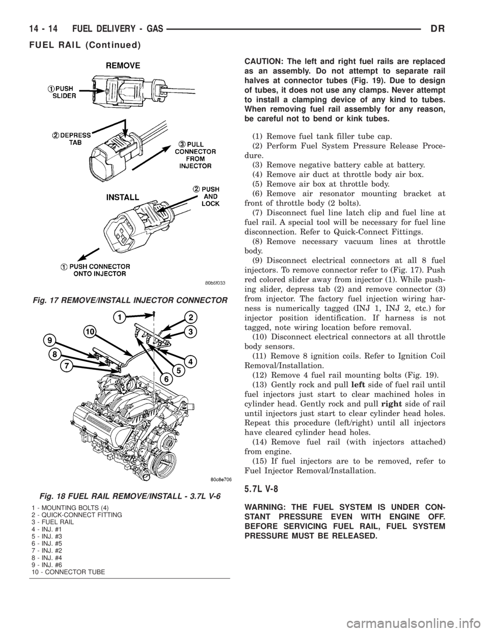
injectors. To remove connector refer to (Fig. 17). Push
red colored slider away from injector (1). While push-
ing slider, depress tab (2) and remove connector (3)
from injector. The factory fuel injection wiring har-
ness is numerically tagged (INJ 1, INJ 2, etc.) for
injector position identification. If harness is not
tagged, note wiring location before removal.
(10) Disconnect electrical connectors at all throttle
body sensors.
(11) Remove 8 ignition coils. Refer to Ignition Coil
Removal/Installation.
(12) Remove 4 fuel rail mounting bolts (Fig. 19).
(13) Gently rock and pullleftside of fuel rail until
fuel injectors just start to clear machined holes in
cylinder head. Gently rock and pullrightside of rail
until injectors just start to clear cylinder head holes.
Repeat this procedure (left/right) until all injectors
have cleared cylinder head holes.
(14) Remove fuel rail (with injectors attached)
from engine.
(15) If fuel injectors are to be removed, refer to
Fuel Injector Removal/Installation.
5.7L V-8
WARNING: THE FUEL SYSTEM IS UNDER CON-
STANT PRESSURE EVEN WITH ENGINE OFF.
BEFORE SERVICING FUEL RAIL, FUEL SYSTEM
PRESSURE MUST BE RELEASED.
Fig. 17 REMOVE/INSTALL INJECTOR CONNECTOR
Fig. 18 FUEL RAIL REMOVE/INSTALL - 3.7L V-6
1 - MOUNTING BOLTS (4)
2 - QUICK-CONNECT FITTING
3 - FUEL RAIL
4 - INJ. #1
5 - INJ. #3
6 - INJ. #5
7 - INJ. #2
8 - INJ. #4
9 - INJ. #6
10 - CONNECTOR TUBE
14 - 14 FUEL DELIVERY - GASDR
FUEL RAIL (Continued)
Page 1712 of 2895
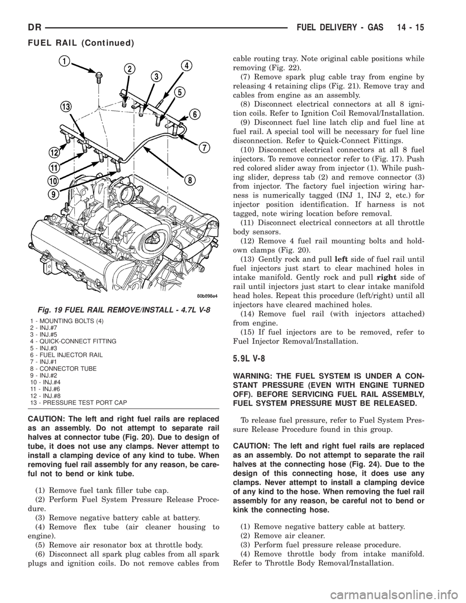
CAUTION: The left and right fuel rails are replaced
as an assembly. Do not attempt to separate rail
halves at connector tube (Fig. 20). Due to design of
tube, it does not use any clamps. Never attempt to
install a clamping device of any kind to tube. When
removing fuel rail assembly for any reason, be care-
ful not to bend or kink tube.
(1) Remove fuel tank filler tube cap.
(2) Perform Fuel System Pressure Release Proce-
dure.
(3) Remove negative battery cable at battery.
(4) Remove flex tube (air cleaner housing to
engine).
(5) Remove air resonator box at throttle body.
(6) Disconnect all spark plug cables from all spark
plugs and ignition coils. Do not remove cables fromcable routing tray. Note original cable positions while
removing (Fig. 22).
(7) Remove spark plug cable tray from engine by
releasing 4 retaining clips (Fig. 21). Remove tray and
cables from engine as an assembly.
(8) Disconnect electrical connectors at all 8 igni-
tion coils. Refer to Ignition Coil Removal/Installation.
(9) Disconnect fuel line latch clip and fuel line at
fuel rail. A special tool will be necessary for fuel line
disconnection. Refer to Quick-Connect Fittings.
(10) Disconnect electrical connectors at all 8 fuel
injectors. To remove connector refer to (Fig. 17). Push
red colored slider away from injector (1). While push-
ing slider, depress tab (2) and remove connector (3)
from injector. The factory fuel injection wiring har-
ness is numerically tagged (INJ 1, INJ 2, etc.) for
injector position identification. If harness is not
tagged, note wiring location before removal.
(11) Disconnect electrical connectors at all throttle
body sensors.
(12) Remove 4 fuel rail mounting bolts and hold-
own clamps (Fig. 20).
(13) Gently rock and pullleftside of fuel rail until
fuel injectors just start to clear machined holes in
intake manifold. Gently rock and pullrightside of
rail until injectors just start to clear intake manifold
head holes. Repeat this procedure (left/right) until all
injectors have cleared machined holes.
(14) Remove fuel rail (with injectors attached)
from engine.
(15) If fuel injectors are to be removed, refer to
Fuel Injector Removal/Installation.
5.9L V-8
WARNING: THE FUEL SYSTEM IS UNDER A CON-
STANT PRESSURE (EVEN WITH ENGINE TURNED
OFF). BEFORE SERVICING FUEL RAIL ASSEMBLY,
FUEL SYSTEM PRESSURE MUST BE RELEASED.
To release fuel pressure, refer to Fuel System Pres-
sure Release Procedure found in this group.
CAUTION: The left and right fuel rails are replaced
as an assembly. Do not attempt to separate the rail
halves at the connecting hose (Fig. 24). Due to the
design of this connecting hose, it does use any
clamps. Never attempt to install a clamping device
of any kind to the hose. When removing the fuel rail
assembly for any reason, be careful not to bend or
kink the connecting hose.
(1) Remove negative battery cable at battery.
(2) Remove air cleaner.
(3) Perform fuel pressure release procedure.
(4) Remove throttle body from intake manifold.
Refer to Throttle Body Removal/Installation.
Fig. 19 FUEL RAIL REMOVE/INSTALL - 4.7L V-8
1 - MOUNTING BOLTS (4)
2 - INJ.#7
3 - INJ.#5
4 - QUICK-CONNECT FITTING
5 - INJ.#3
6 - FUEL INJECTOR RAIL
7 - INJ.#1
8 - CONNECTOR TUBE
9 - INJ.#2
10 - INJ.#4
11 - INJ.#6
12 - INJ.#8
13 - PRESSURE TEST PORT CAP
DRFUEL DELIVERY - GAS 14 - 15
FUEL RAIL (Continued)
Page 1716 of 2895
(11) Connect necessary vacuum lines to throttle
body.
(12) Install air resonator mounting bracket near
front of throttle body (2 bolts).
(13) Connect fuel line latch clip and fuel line to
fuel rail. Refer to Quick-Connect Fittings.
(14) Install air box to throttle body.
(15) Install air duct to air box.
(16) Connect battery cable to battery.
(17) Start engine and check for leaks.
4.7L V-8
(1) If fuel injectors are to be installed, refer to Fuel
Injector Removal/Installation.
(2) Clean out fuel injector machined bores in
intake manifold.
(3) Apply a small amount of engine oil to each fuel
injector o-ring. This will help in fuel rail installation.
(4) Position fuel rail/fuel injector assembly to
machined injector openings in cylinder head.
(5) Guide each injector into cylinder head. Be care-
ful not to tear injector o-rings.
(6) Pushrightside of fuel rail down until fuel
injectors have bottomed on cylinder head shoulder.
Pushleftfuel rail down until injectors have bot-
tomed on cylinder head shoulder.
(7) Install 4 fuel rail mounting bolts and tighten.
Refer to torque specifications.
(8) Install 8 ignition coils. Refer to Ignition Coil
Removal/Installation.
(9) Connect electrical connectors to throttle body.
(10) Connect electrical connectors at all fuel injec-
tors. To install connector, refer to (Fig. 17). Push con-
nector onto injector (1) and then push and lock red
colored slider (2). Verify connector is locked to injec-
tor by lightly tugging on connector.
(11) Connect necessary vacuum lines to throttle
body.
(12) Install air resonator mounting bracket near
front of throttle body (2 bolts).
(13) Connect fuel line latch clip and fuel line to
fuel rail. Refer to Quick-Connect Fittings.
(14) Install air box to throttle body.
(15) Install air duct to air box.
(16) Connect battery cable to battery.
(17) Start engine and check for leaks.
5.7L V-8
(1) If fuel injectors are to be installed, refer to Fuel
Injector Removal/Installation.
(2) Clean out fuel injector machined bores in
intake manifold.
(3) Apply a small amount of engine oil to each fuel
injector o-ring. This will help in fuel rail installation.
(4) Position fuel rail/fuel injector assembly to
machined injector openings in intake manifold.(5) Guide each injector into intake manifold. Be
careful not to tear injector o-rings.
(6) Pushrightside of fuel rail down until fuel
injectors have bottomed on shoulders. Pushleftfuel
rail down until injectors have bottomed on shoulders.
(7) Install 4 fuel rail holdown clamps and 4 mount-
ing bolts. Refer to Torque Specifications.
(8) Position spark plug cable tray and cable assem-
bly to intake manifold. Snap 4 cable tray retaining
clips into intake manifold.
(9) Install all cables to spark plugs and ignition
coils.
(10) Connect electrical connector to throttle body.
(11) Install electrical connectors to all 8 ignition
coils. Refer to Ignition Coil Removal/Installation.
(12) Connect electrical connector to throttle body.
(13) Connect electrical connectors at all fuel injec-
tors. To install connector, refer to (Fig. 17). Push con-
nector onto injector (1) and then push and lock red
colored slider (2). Verify connector is locked to injec-
tor by lightly tugging on connector.
(14) Connect fuel line latch clip and fuel line to
fuel rail. Refer to Quick-Connect Fittings.
(15) Install air resonator to throttle body (2 bolts).
(16) Install flexible air duct to air box.
(17) Connect battery cable to battery.
(18) Start engine and check for leaks.
5.9L V-8
(1) If fuel injectors are to be installed, refer to Fuel
Injector Removal/Installation.
(2) Apply a small amount of engine oil to each fuel
injector o-ring. This will help in fuel rail installation.
(3) Clean out fuel injector machined bores in
intake manifold.
(4) Position fuel rail/fuel injector assembly to injec-
tor openings on intake manifold.
(5) Guide each injector into intake manifold. Be
careful not to tear injector o-ring.
(6) Push therightfuel rail down until fuel injec-
tors have bottomed on injector shoulder. Push the
leftfuel rail down until fuel injectors have bottomed
on injector shoulder.
(7) Install fuel rail mounting bolts. Refer to Torque
Specifications.
(8) Connect electrical connector to intake manifold
air temperature sensor.
(9) Connect electrical connectors at all fuel injec-
tors. To install connector, refer to (Fig. 17). Push con-
nector onto injector (1) and then push and lock red
colored slider (2). Verify connector is locked to injec-
tor by lightly tugging on connector.
(10) Install fuel tube (line) at side of fuel rail.
Refer to Quick-Connect Fittings for procedures.
(11) Install air cleaner resonator to throttle body.
(12) Connect battery cable to battery.
DRFUEL DELIVERY - GAS 14 - 19
FUEL RAIL (Continued)
Page 1721 of 2895
FUEL INJECTION - GAS
TABLE OF CONTENTS
page page
ACCELERATOR PEDAL
REMOVAL.............................24
INSTALLATION.........................24
ACCELERATOR PEDAL POSITION SENSOR
DESCRIPTION.........................25
OPERATION...........................25
REMOVAL.............................25
INSTALLATION.........................25
CRANKSHAFT POSITION SENSOR
DESCRIPTION.........................26
OPERATION...........................26
REMOVAL.............................29
INSTALLATION.........................30
FUEL INJECTOR
DESCRIPTION.........................32
OPERATION
OPERATION - FUEL INJECTOR..........32
OPERATION - PCM OUTPUT............32
REMOVAL.............................32
INSTALLATION.........................33
FUEL PUMP RELAY
DESCRIPTION.........................33
OPERATION...........................33
REMOVAL.............................33
INSTALLATION.........................33
IDLE AIR CONTROL MOTOR
DESCRIPTION.........................33
OPERATION...........................33
REMOVAL.............................34INSTALLATION.........................35
INTAKE AIR TEMPERATURE SENSOR
DESCRIPTION.........................36
OPERATION...........................36
REMOVAL.............................36
INSTALLATION.........................38
MAP SENSOR
DESCRIPTION.........................39
OPERATION...........................39
REMOVAL.............................40
INSTALLATION.........................42
OXYGEN SENSOR
DESCRIPTION.........................43
OPERATION...........................43
REMOVAL.............................44
INSTALLATION.........................45
THROTTLE BODY
DESCRIPTION.........................45
OPERATION...........................45
REMOVAL.............................45
INSTALLATION.........................47
THROTTLE CONTROL CABLE
REMOVAL.............................49
INSTALLATION.........................51
THROTTLE POSITION SENSOR
DESCRIPTION.........................52
OPERATION...........................52
REMOVAL.............................53
INSTALLATION.........................54
ACCELERATOR PEDAL
REMOVAL
The following procedure applies only to vehicles
without the Adjustable Pedal Package (code XAP).
The accelerator pedal is serviced as a complete
assembly including the bracket.
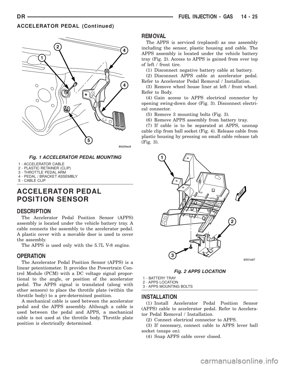
The accelerator cable is connected to the upper
part of the accelerator pedal arm by a plastic
retainer (clip) (Fig. 1). This plastic retainer snaps
into the top of the accelerator pedal arm.
(1) From inside the vehicle, hold up accelerator
pedal. Remove plastic cable retainer (clip) and throt-
tle cable core wire from upper end of accelerator
pedal arm (Fig. 1). Plastic cable retainer (clip) snaps
into pedal arm.(2) Remove 2 accelerator pedal mounting bracket
nuts. Remove accelerator pedal assembly.INSTALLATION
(1) Place accelerator pedal assembly over 2 studs.
(2) Install and tighten 2 mounting nuts. Refer to
Torque Specifications.
(3) Slide throttle cable into opening slot in top of
pedal arm.
(4) Push plastic cable retainer (clip) into accelera-
tor pedal arm opening until it snaps into place.
(5) Before starting engine, operate accelerator
pedal to check for any binding.
14 - 24 FUEL INJECTION - GASDR
Page 1722 of 2895
ACCELERATOR PEDAL
POSITION SENSOR
DESCRIPTION
The Accelerator Pedal Position Sensor (APPS)
assembly is located under the vehicle battery tray. A
cable connects the assembly to the accelerator pedal.
A plastic cover with a movable door is used to cover
the assembly.
The APPS is used only with the 5.7L V-8 engine.
OPERATION
The Accelerator Pedal Position Sensor (APPS) is a
linear potentiometer. It provides the Powertrain Con-
trol Module (PCM) with a DC voltage signal propor-
tional to the angle, or position of the accelerator
pedal. The APPS signal is translated (along with
other sensors) to place the throttle plate (within the
throttle body) to a pre-determined position.
A mechanical cable is used between the accelerator
pedal and the APPS assembly. Although a cable is
used between the pedal and APPS, a mechanical
cable is not used at the throttle body. Throttle plate
position is electrically determined.
REMOVAL
The APPS is serviced (replaced) as one assembly
including the sensor, plastic housing and cable. The
APPS assembly is located under the vehicle battery
tray (Fig. 2). Access to APPS is gained from over top
of left / front tire.
(1) Disconnect negative battery cable at battery.
(2) Disconnect APPS cable at accelerator pedal.
Refer to Accelerator Pedal Removal / Installation.
(3) Remove wheel house liner at left / front wheel.
Refer to Body.
(4) Gain access to APPS electrical connector by
opening swing-down door (Fig. 3). Disconnect electri-
cal connector.
(5) Remove 3 mounting bolts (Fig. 3).
(6) Remove APPS assembly from battery tray.
(7) If cable is to be separated at APPS, unsnap
cable clip from ball socket (Fig. 4). Release cable from
plastic housing by pressing on small cable release tab
(Fig. 3).
INSTALLATION
(1) Install Accelerator Pedal Position Sensor
(APPS) cable to accelerator pedal. Refer to Accelera-
tor Pedal Removal / Installation.
(2) Connect electrical connector to APPS.
(3) If necessary, connect cable to APPS lever ball
socket (snaps on).
(4) Snap APPS cable cover closed.
Fig. 1 ACCELERATOR PEDAL MOUNTING
1 - ACCELERATOR CABLE
2 - PLASTIC RETAINER (CLIP)
3 - THROTTLE PEDAL ARM
4 - PEDAL / BRACKET ASSEMBLY
5 - CABLE CLIP
Fig. 2 APPS LOCATION
1 - BATTERY TRAY
2 - APPS LOCATION
3 - APPS MOUNTING BOLTS
DRFUEL INJECTION - GAS 14 - 25
ACCELERATOR PEDAL (Continued)