2003 DODGE RAM belt
[x] Cancel search: beltPage 1601 of 2895
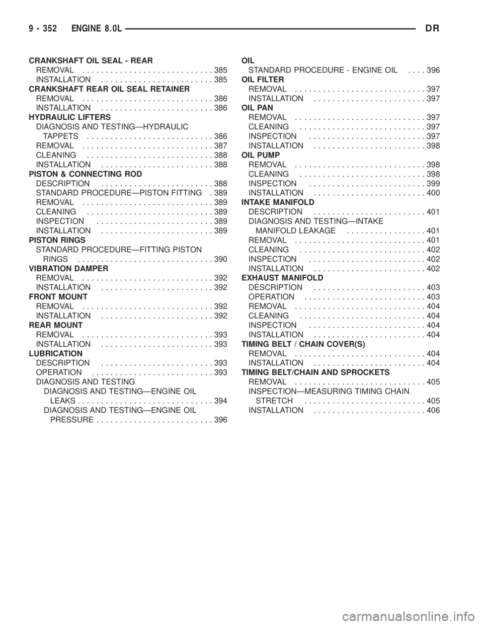
CRANKSHAFT OIL SEAL - REAR
REMOVAL............................385
INSTALLATION........................385
CRANKSHAFT REAR OIL SEAL RETAINER
REMOVAL............................386
INSTALLATION........................386
HYDRAULIC LIFTERS
DIAGNOSIS AND TESTINGÐHYDRAULIC
TAPPETS...........................386
REMOVAL............................387
CLEANING...........................388
INSTALLATION........................388
PISTON & CONNECTING ROD
DESCRIPTION........................388
STANDARD PROCEDUREÐPISTON FITTING . 389
REMOVAL............................389
CLEANING...........................389
INSPECTION.........................389
INSTALLATION........................389
PISTON RINGS
STANDARD PROCEDUREÐFITTING PISTON
RINGS.............................390
VIBRATION DAMPER
REMOVAL............................392
INSTALLATION........................392
FRONT MOUNT
REMOVAL............................392
INSTALLATION........................392
REAR MOUNT
REMOVAL............................393
INSTALLATION........................393
LUBRICATION
DESCRIPTION........................393
OPERATION..........................393
DIAGNOSIS AND TESTING
DIAGNOSIS AND TESTINGÐENGINE OIL
LEAKS.............................394
DIAGNOSIS AND TESTINGÐENGINE OIL
PRESSURE.........................396OIL
STANDARD PROCEDURE - ENGINE OIL....396
OIL FILTER
REMOVAL............................397
INSTALLATION........................397
OIL PAN
REMOVAL............................397
CLEANING...........................397
INSPECTION.........................397
INSTALLATION........................398
OIL PUMP
REMOVAL............................398
CLEANING...........................398
INSPECTION.........................399
INSTALLATION........................400
INTAKE MANIFOLD
DESCRIPTION........................401
DIAGNOSIS AND TESTINGÐINTAKE
MANIFOLD LEAKAGE.................401
REMOVAL............................401
CLEANING...........................402
INSPECTION.........................402
INSTALLATION........................402
EXHAUST MANIFOLD
DESCRIPTION........................403
OPERATION..........................403
REMOVAL............................404
CLEANING...........................404
INSPECTION.........................404
INSTALLATION........................404
TIMING BELT / CHAIN COVER(S)
REMOVAL............................404
INSTALLATION........................404
TIMING BELT/CHAIN AND SPROCKETS
REMOVAL............................405
INSPECTIONÐMEASURING TIMING CHAIN
STRETCH..........................405
INSTALLATION........................406
9 - 352 ENGINE 8.0LDR
Page 1603 of 2895
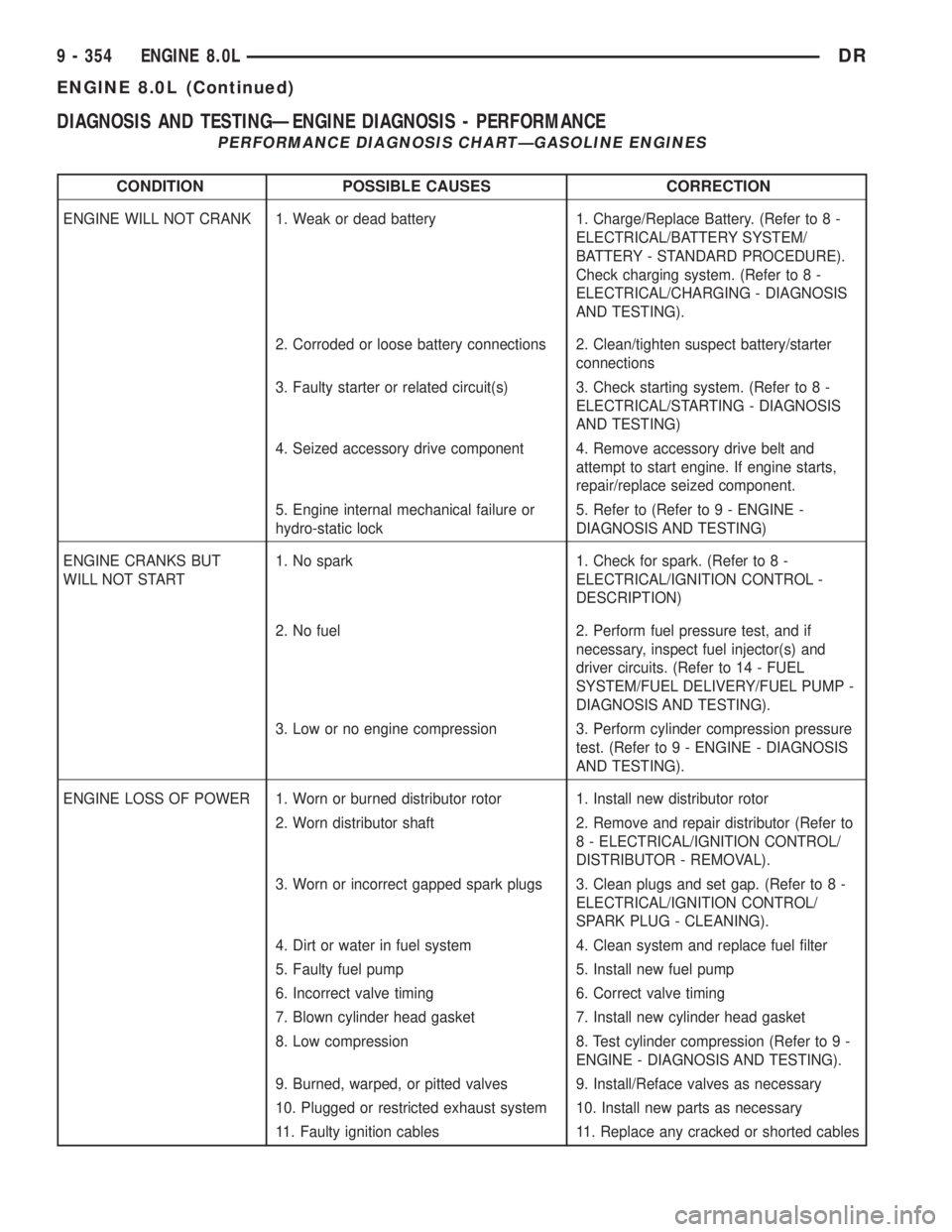
DIAGNOSIS AND TESTINGÐENGINE DIAGNOSIS - PERFORMANCE
PERFORMANCE DIAGNOSIS CHARTÐGASOLINE ENGINES
CONDITION POSSIBLE CAUSES CORRECTION
ENGINE WILL NOT CRANK 1. Weak or dead battery 1. Charge/Replace Battery. (Refer to 8 -
ELECTRICAL/BATTERY SYSTEM/
BATTERY - STANDARD PROCEDURE).
Check charging system. (Refer to 8 -
ELECTRICAL/CHARGING - DIAGNOSIS
AND TESTING).
2. Corroded or loose battery connections 2. Clean/tighten suspect battery/starter
connections
3. Faulty starter or related circuit(s) 3. Check starting system. (Refer to 8 -
ELECTRICAL/STARTING - DIAGNOSIS
AND TESTING)
4. Seized accessory drive component 4. Remove accessory drive belt and
attempt to start engine. If engine starts,
repair/replace seized component.
5. Engine internal mechanical failure or
hydro-static lock5. Refer to (Refer to 9 - ENGINE -
DIAGNOSIS AND TESTING)
ENGINE CRANKS BUT
WILL NOT START1. No spark 1. Check for spark. (Refer to 8 -
ELECTRICAL/IGNITION CONTROL -
DESCRIPTION)
2. No fuel 2. Perform fuel pressure test, and if
necessary, inspect fuel injector(s) and
driver circuits. (Refer to 14 - FUEL
SYSTEM/FUEL DELIVERY/FUEL PUMP -
DIAGNOSIS AND TESTING).
3. Low or no engine compression 3. Perform cylinder compression pressure
test. (Refer to 9 - ENGINE - DIAGNOSIS
AND TESTING).
ENGINE LOSS OF POWER 1. Worn or burned distributor rotor 1. Install new distributor rotor
2. Worn distributor shaft 2. Remove and repair distributor (Refer to
8 - ELECTRICAL/IGNITION CONTROL/
DISTRIBUTOR - REMOVAL).
3. Worn or incorrect gapped spark plugs 3. Clean plugs and set gap. (Refer to 8 -
ELECTRICAL/IGNITION CONTROL/
SPARK PLUG - CLEANING).
4. Dirt or water in fuel system 4. Clean system and replace fuel filter
5. Faulty fuel pump 5. Install new fuel pump
6. Incorrect valve timing 6. Correct valve timing
7. Blown cylinder head gasket 7. Install new cylinder head gasket
8. Low compression 8. Test cylinder compression (Refer to 9 -
ENGINE - DIAGNOSIS AND TESTING).
9. Burned, warped, or pitted valves 9. Install/Reface valves as necessary
10. Plugged or restricted exhaust system 10. Install new parts as necessary
11. Faulty ignition cables 11. Replace any cracked or shorted cables
9 - 354 ENGINE 8.0LDR
ENGINE 8.0L (Continued)
Page 1611 of 2895
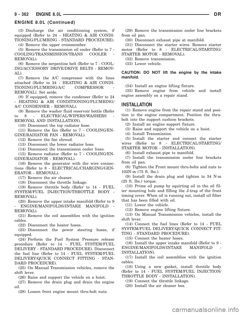
(3) Discharge the air conditioning system, if
equipped (Refer to 24 - HEATING & AIR CONDI-
TIONING/PLUMBING - STANDARD PROCEDURE).
(4) Remove the upper crossmember.
(5) Remove the transmission oil cooler (Refer to 7 -
COOLING/TRANSMISSION/TRANS COOLER -
REMOVAL).
(6) Remove the serpentine belt (Refer to 7 - COOL-
ING/ACCESSORY DRIVE/DRIVE BELTS - REMOV-
AL).
(7) Remove the A/C compressor with the lines
attached (Refer to 24 - HEATING & AIR CONDI-
TIONING/PLUMBING/A/C COMPRESSOR -
REMOVAL). Set aside.
(8) If equipped, remove the condenser (Refer to 24
- HEATING & AIR CONDITIONING/PLUMBING/
A/C CONDENSER - REMOVAL).
(9) Remove the washer fluid reservoir bottle (Refer
to 8 - ELECTRICAL/WIPERS/WASHERS -
REMOVAL AND INSTALLATION).
(10) Disconnect the top radiator hose.
(11) Remove the fan (Refer to 7 - COOLING/EN-
GINE/RADIATOR FAN - REMOVAL).
(12) Remove the fan shroud.
(13) Disconnect the lower radiator hose.
(14) Disconnect the transmission cooler lines.
(15) Remove radiator (Refer to 7 - COOLING/EN-
GINE/RADIATOR - REMOVAL).
(16) Remove the generator with the wire connec-
tions (Refer to 8 - ELECTRICAL/CHARGING/GEN-
ERATOR - REMOVAL).
(17) Remove the air cleaner.
(18) Disconnect the throttle linkage.
(19) Remove throttle body (Refer to 14 - FUEL
SYSTEM/FUEL INJECTION/THROTTLE BODY -
REMOVAL).
(20) Remove the upper intake manifold (Refer to 9
- ENGINE/MANIFOLDS/INTAKE MANIFOLD -
REMOVAL).
(21) Remove the coil assemblies with the ignition
cables.
(22) Disconnect the heater hoses.
(23) Disconnect the power steering hoses, if
equipped.
(24) Perform the Fuel System Pressure release
procedure (Refer to 14 - FUEL SYSTEM/FUEL
DELIVERY - STANDARD PROCEDURE). Disconnect
the fuel line (Refer to 14 - FUEL SYSTEM/FUEL
DELIVERY/QUICK CONNECT FITTING - STAN-
DARD PROCEDURE).
(25) On Manual Transmission vehicles, remove the
shift lever.
(26) Raise and support the vehicle on a hoist.
(27) Remove the drain plug and drain the engine
oil.
(28) Loosen front engine mount thru-bolt nuts.(29) Remove the transmission cooler line brackets
from oil pan.
(30) Disconnect exhaust pipe at manifold.
(31) Disconnect the starter wires. Remove starter
motor (Refer to 8 - ELECTRICAL/STARTING/
STARTER MOTOR - REMOVAL).
(32) Remove transmission.
(33) Lower vehicle.
CAUTION: DO NOT lift the engine by the intake
manifold.
(34) Install an engine lifting fixture.
(35) Remove engine from vehicle and install
engine assembly on a repair stand.
INSTALLATION
(1) Remove engine from the repair stand and posi-
tion in the engine compartment. Position the thru-
bolt into the support cushion brackets.
(2) Install an engine support fixture.
(3) Raise and support the vehicle on a hoist.
(4) Install Transmission.
(5) Install the starter and connect the starter
wires (Refer to 8 - ELECTRICAL/STARTING/
STARTER MOTOR - INSTALLATION).
(6) Install exhaust pipe to manifold.
(7) Install the transmission cooler line brackets
from oil pan.
(8) Tighten the Front mount thru-bolts and nuts to
102N´m (75 ft. lbs.).
(9) Install the drain plug and tighten to 34 N´m
(25 ft. lbs.) torque.
(10) Prime oil pump by squirting oil in the oil fil-
ter mounting hole and filling the J-trap of the front
timing cover. When oil is running out, install oil filter
that has been filled with oil.
(11) Lower the vehicle.
(12) Remove engine lifting fixture.
(13) On Manual Transmission vehicles, install the
shift lever.
(14) Connect the fuel lines (Refer to 14 - FUEL
SYSTEM/FUEL DELIVERY/QUICK CONNECT FIT-
TING - STANDARD PROCEDURE).
(15) Connect the heater hoses.
(16) Install the upper intake manifold (Refer to 9 -
ENGINE/MANIFOLDS/INTAKE MANIFOLD -
INSTALLATION).
(17) Install the coil assemblies with the ignition
cables.
(18) Using a new gasket, install throttle body
(Refer to 14 - FUEL SYSTEM/FUEL INJECTION/
THROTTLE BODY - INSTALLATION).
(19) Connect the throttle linkage.
(20) Install the air cleaner box.
9 - 362 ENGINE 8.0LDR
ENGINE 8.0L (Continued)
Page 1612 of 2895
(21) Install the generator and wire connections
(Refer to 8 - ELECTRICAL/CHARGING/GENERA-
TOR - INSTALLATION).
(22) Install the upper crossmember.
(23) Install radiator (Refer to 7 - COOLING/EN-
GINE/RADIATOR - INSTALLATION).
(24) Connect the lower radiator hose.
(25) Install the transmission oil cooler (Refer to 7 -
COOLING/TRANSMISSION/TRANS COOLER -
INSTALLATION).
(26) Connect the transmission cooler lines.
(27) Connect the power steering hoses, if equipped.
(28) Install the fan shroud.
(29) Install the fan (Refer to 7 - COOLING/EN-
GINE/RADIATOR FAN - INSTALLATION).
(30) Connect the top radiator hose.
(31) Install the washer fluid reservoir bottle (Refer
to 8 - ELECTRICAL/WIPERS/WASHERS - INSTAL-
LATION).
(32) If equipped, install the condenser (Refer to 24
- HEATING & AIR CONDITIONING/PLUMBING/
A/C CONDENSER - INSTALLATION).
(33) Install the A/C compressor with the lines
attached (Refer to 24 - HEATING & AIR CONDI-
TIONING/PLUMBING/A/C COMPRESSOR -
INSTALLATION).
(34) Install the serpentine belt (Refer to 7 - COOL-
ING/ACCESSORY DRIVE/DRIVE BELTS - INSTAL-
LATION).
(35) Evacuate (Refer to 24 - HEATING & AIR
CONDITIONING/PLUMBING - STANDARD PRO-
CEDURE) and charge the air conditioning system, if
equipped (Refer to 24 - HEATING & AIR CONDI-
TIONING/PLUMBING - STANDARD PROCEDURE).
(36) Add coolant to the cooling system (Refer to 7 -
COOLING - STANDARD PROCEDURE).
(37) Install the battery.
(38) Warm engine and adjust as required.
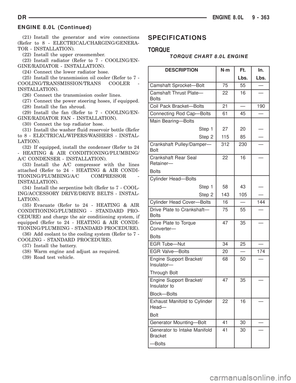
(39) Road test vehicle.SPECIFICATIONS
TORQUE
TORQUE CHART 8.0L ENGINE
DESCRIPTION N´m Ft. In.
Lbs. Lbs.
Camshaft SprocketÐBolt 75 55 Ð
Camshaft Thrust PlateÐ
Bolts22 16 Ð
Coil Pack BracketÐBolts 21 Ð 190
Connecting Rod CapÐBolts 61 45 Ð
Main BearingÐBolts
Step 1 27 20 Ð
Step 2 115 85 Ð
Crankshaft Pulley/DamperÐ
Bolt312 230 Ð
Crankshaft Rear Seal
RetainerÐ22 16 Ð
Bolts
Cylinder HeadÐBolts
Step 1 58 43 Ð
Step 2 143 105 Ð
Cylinder Head CoverÐBolts 16 Ð 144
Drive Plate to CrankshaftÐ
Bolts75 55 Ð
Drive Plate to Torque
ConverterÐ47 35 Ð
Bolts
EGR TubeÐNut 34 25 Ð
EGR ValveÐBolts 20 Ð 174
Engine Support Bracket/
InsulatorÐ68 50 Ð
Through Bolt
Engine Support Bracket/
Insulator to47 35 Ð
BlockÐBolts
Exhaust Manifold to Cylinder
HeadÐ22 16 Ð
Bolt
Generator MountingÐBolt 41 30 Ð
Generator to Intake Manifold
Bracket41 30 Ð
ÐBolts
DRENGINE 8.0L 9 - 363
ENGINE 8.0L (Continued)
Page 1622 of 2895
(4) Install push rods and rocker arm assemblies in
their original position (Refer to 9 - ENGINE/CYLIN-
DER HEAD/ROCKER ARM / ADJUSTER ASSY -
INSTALLATION).
(5) Install lower intake manifold (Refer to 9 -
ENGINE/MANIFOLDS/INTAKE MANIFOLD -
INSTALLATION).
(6) Install the upper intake manifold onto the
lower intake manifold (Refer to 9 - ENGINE/MANI-
FOLDS/INTAKE MANIFOLD - INSTALLATION).
(7) Install the exhaust manifolds and new gaskets
(Refer to 9 - ENGINE/MANIFOLDS/EXHAUST
MANIFOLD - INSTALLATION).
(8) Install exhaust pipe to the exhaust manifold.
Tighten the bolts to 34 n´m (25 ft. lbs.) torque.
(9) Using a new gasket, position the EGR tube to
the intake manifold and the exhaust manifold.
Tighten the EGR tube nut to 34 N´m (25 ft. lbs.)
torque. Tighten the bolts to 20 N´m (174 in. lbs.)
torque.
(10) Install the heat shields and the washers.
Make sure that heat shields tabs hook over the
exhaust gasket.Tighten the nuts to 15 N´m (132 in.
lbs.) torque.
(11) Adjust and Install the spark plugs (Refer to 8
- ELECTRICAL/IGNITION CONTROL/SPARK
PLUG - INSTALLATION).
(12) Install coil packs and bracket. Tighten the
bracket bolts to 21 N´m (190 in. lbs.) torque. Connect
the coil wires.
(13) Connect heat indicator sending unit wire.
(14) Connect the heater hoses and bypass hose.
(15) Connect the accelerator linkage and if so
equipped, the speed control and transmission kick-
down cables.
(16) Install the fuel line (Refer to 14 - FUEL SYS-
TEM/FUEL DELIVERY/QUICK CONNECT FIT-
TING - STANDARD PROCEDURE).
(17) Install the generator (Refer to 8 - ELECTRI-
CAL/CHARGING/GENERATOR - INSTALLATION)
and drive belt (Refer to 7 - COOLING/ACCESSORY
DRIVE/DRIVE BELTS - INSTALLATION).
(18) Install the intake manifold-to-generator
bracket support rod. Tighten the bolts to 41 N´m (30
ft. lbs.) torque.
(19) The cylinder head cover gasket can be used
again. Install the gasket onto the head rail.For the
left side the number tab is at the front of
engine with the number up. For the right side
the number tab is at the rear of engine with the
number up.
CAUTION: The cylinder head cover fasteners have a
special plating. DO NOT use alternative fasteners.(20) Install cylinder head cover (Refer to 9 -
ENGINE/CYLINDER HEAD/CYLINDER HEAD
COVER(S) - INSTALLATION).
(21) Install closed crankcase ventilation system.
(22) Connect the evaporation control system.
(23) Install the air cleaner.
(24) Fill cooling system (Refer to 7 - COOLING -
STANDARD PROCEDURE).
(25) Connect the negative cable to the battery.
(26) Check for leaks (fuel, oil, antifreeze, etc.).
CYLINDER HEAD COVER(S)
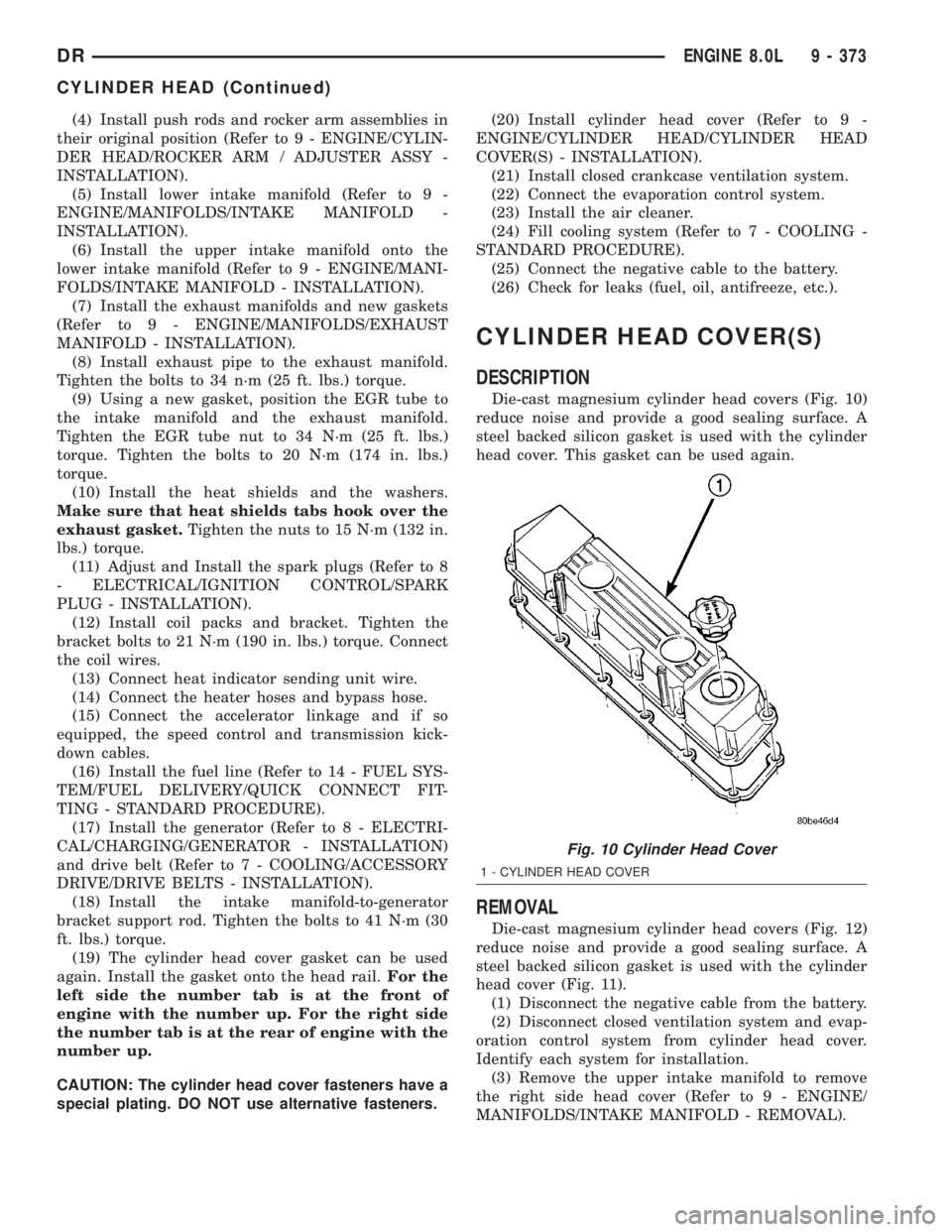
DESCRIPTION
Die-cast magnesium cylinder head covers (Fig. 10)
reduce noise and provide a good sealing surface. A
steel backed silicon gasket is used with the cylinder
head cover. This gasket can be used again.
REMOVAL
Die-cast magnesium cylinder head covers (Fig. 12)
reduce noise and provide a good sealing surface. A
steel backed silicon gasket is used with the cylinder
head cover (Fig. 11).
(1) Disconnect the negative cable from the battery.
(2) Disconnect closed ventilation system and evap-
oration control system from cylinder head cover.
Identify each system for installation.
(3) Remove the upper intake manifold to remove
the right side head cover (Refer to 9 - ENGINE/
MANIFOLDS/INTAKE MANIFOLD - REMOVAL).
Fig. 10 Cylinder Head Cover
1 - CYLINDER HEAD COVER
DRENGINE 8.0L 9 - 373
CYLINDER HEAD (Continued)
Page 1629 of 2895
(1) Install the push rods in the same order as
removed.
(2) Install rocker arm assemblies in the same
order as removed. Tighten the rocker arm bolts to 53
N´m (40 ft. lbs.) torque.
(3) Install cylinder head cover and gasket (Refer to
9 - ENGINE/CYLINDER HEAD/CYLINDER HEAD
COVER(S) - INSTALLATION).
(4) Connect spark plug wires.
ENGINE BLOCK
CLEANING
Clean cylinder block thoroughly and check all core
hole plugs for evidence of leaking.
INSPECTION
Examine block for cracks or fractures.
The cylinder walls should be checked for out-of-
round and taper with Cylinder Bore Indicator Tool,
Special tool 6879 or equivalent. The cylinder block
should be bored and honed with new pistons and
rings fitted if:
²The cylinder bores show more than 0.127 mm
(0.005 inch) out-of-round.
²The cylinder bores show a taper of more than
0.254 mm (0.010 inch).
²The cylinder walls are badly scuffed or scored.
Boring and honing operation should be closely coor-
dinated with the fitting of pistons and rings so spec-
ified clearances may be maintained.
CAMSHAFT & BEARINGS (IN
BLOCK)
REMOVAL
REMOVALÐCAMSHAFT BEARINGS
This procedure requires that the engine is removed
from the vehicle.
(1) With engine completely disassembled, drive out
rear cam bearing core hole plug.
NOTE: It is not advisable to attempt to replace cam-
shaft bearings unless special removal and installa-
tion tools are available, such as recommended tool
8544 Camshaft Bushing Remover Installer.
(2) Using recommended tool 8544 Camshaft Bush-
ing Remover Installer, Drive out bearing shells.
REMOVALÐCAMSHAFT
(1) Remove rocker arms and push rods (Refer to 9
- ENGINE/CYLINDER HEAD/ROCKER ARM /
ADJUSTER ASSY - REMOVAL). Identify each part
so it can be installed in its original location.
NOTE: The 4 corner tappets can not be removed
without removing the cylinder heads and gaskets.
However, they can be lifted and retained for cam-
shaft removal.
(2) Remove the Bolts retaining the yoke retaining
spider. Remove the yoke retaining spider, tappet
aligning yokes and tappets.
(3) Remove upper and lower intake manifolds
(Refer to 9 - ENGINE/MANIFOLDS/INTAKE MANI-
FOLD - REMOVAL).
(4) Remove timing chain cover (Refer to 9 -
ENGINE/VALVE TIMING/TIMING BELT / CHAIN
COVER(S) - REMOVAL) and timing chain and
sprockets (Refer to 9 - ENGINE/VALVE TIMING/
TIMING BELT/CHAIN AND SPROCKETS -
REMOVAL).
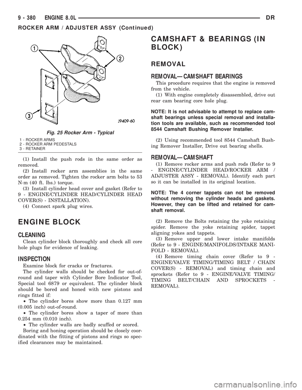
Fig. 25 Rocker Arm - Typical
1 - ROCKER ARMS
2 - ROCKER ARM PEDESTALS
3 - RETAINER
9 - 380 ENGINE 8.0LDR
ROCKER ARM / ADJUSTER ASSY (Continued)
Page 1630 of 2895
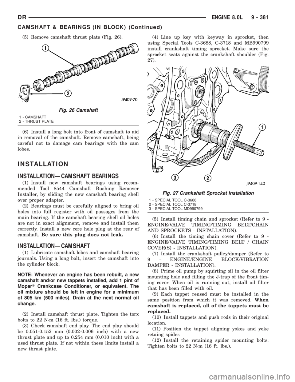
(5) Remove camshaft thrust plate (Fig. 26).
(6) Install a long bolt into front of camshaft to aid
in removal of the camshaft. Remove camshaft, being
careful not to damage cam bearings with the cam
lobes.
INSTALLATION
INSTALLATIONÐCAMSHAFT BEARINGS
(1) Install new camshaft bearings using recom-
mended Tool 8544 Camshaft Bushing Remover
Installer, by sliding the new camshaft bearing shell
over proper adapter.
(2) Bearings must be carefully aligned to bring oil
holes into full register with oil passages from the
main bearing. If the camshaft bearing shell oil holes
are not in exact alignment, remove and install them
correctly. Install a new core hole plug at the rear of
camshaft.Be sure this plug does not leak.
INSTALLATIONÐCAMSHAFT
(1) Lubricate camshaft lobes and camshaft bearing
journals. Using a long bolt, insert the camshaft into
the cylinder block.
NOTE: Whenever an engine has been rebuilt, a new
camshaft and/or new tappets installed, add 1 pint of
MoparTCrankcase Conditioner, or equivalent. The
oil mixture should be left in engine for a minimum
of 805 km (500 miles). Drain at the next normal oil
change.
(2) Install camshaft thrust plate. Tighten the torx
bolts to 22 N´m (16 ft. lbs.) torque.
(3) Check camshaft end play. The end play should
be 0.051-0.152 mm (0.002-0.006 inch) with a new
thrust plate and up to 0.254 mm (0.010 inch) with a
used thrust plate. If not within these limits install a
new thrust plate.(4) Line up key with keyway in sprocket, then
using Special Tools C-3688, C-3718 and MB990799
install crankshaft timing sprocket. Make sure the
sprocket seats against the crankshaft shoulder (Fig.
27).
(5) Install timing chain and sprocket (Refer to 9 -
ENGINE/VALVE TIMING/TIMING BELT/CHAIN
AND SPROCKETS - INSTALLATION).
(6) Install the timing chain cover (Refer to 9 -
ENGINE/VALVE TIMING/TIMING BELT / CHAIN
COVER(S) - INSTALLATION).
(7) Install the crankshaft pulley/damper (Refer to
9 - ENGINE/ENGINE BLOCK/VIBRATION
DAMPER - INSTALLATION).
(8) Prime oil pump by squirting oil in the oil filter
mounting hole and filling the J-trap of the front tim-
ing cover. When oil is running out, install oil filter
that has been filled with oil.
(9) Each tappet reused must be installed in the
same position from which it was removed.When
camshaft is replaced, all of the tappets must be
replaced.
(10) Install tappets and push rods in their original
location.
(11) Position the tappet aligning yokes and yoke
retaing spider.
(12) Install the retaining spider mounting bolts.
Tighten bolts to 22 N´m (16 ft. lbs.).
Fig. 26 Camshaft
1 - CAMSHAFT
2 - THRUST PLATE
Fig. 27 Crankshaft Sprocket Installation
1 - SPECIAL TOOL C-3688
2 - SPECIAL TOOL C-3718
3 - SPECIAL TOOL MD990799
DRENGINE 8.0L 9 - 381
CAMSHAFT & BEARINGS (IN BLOCK) (Continued)
Page 1633 of 2895
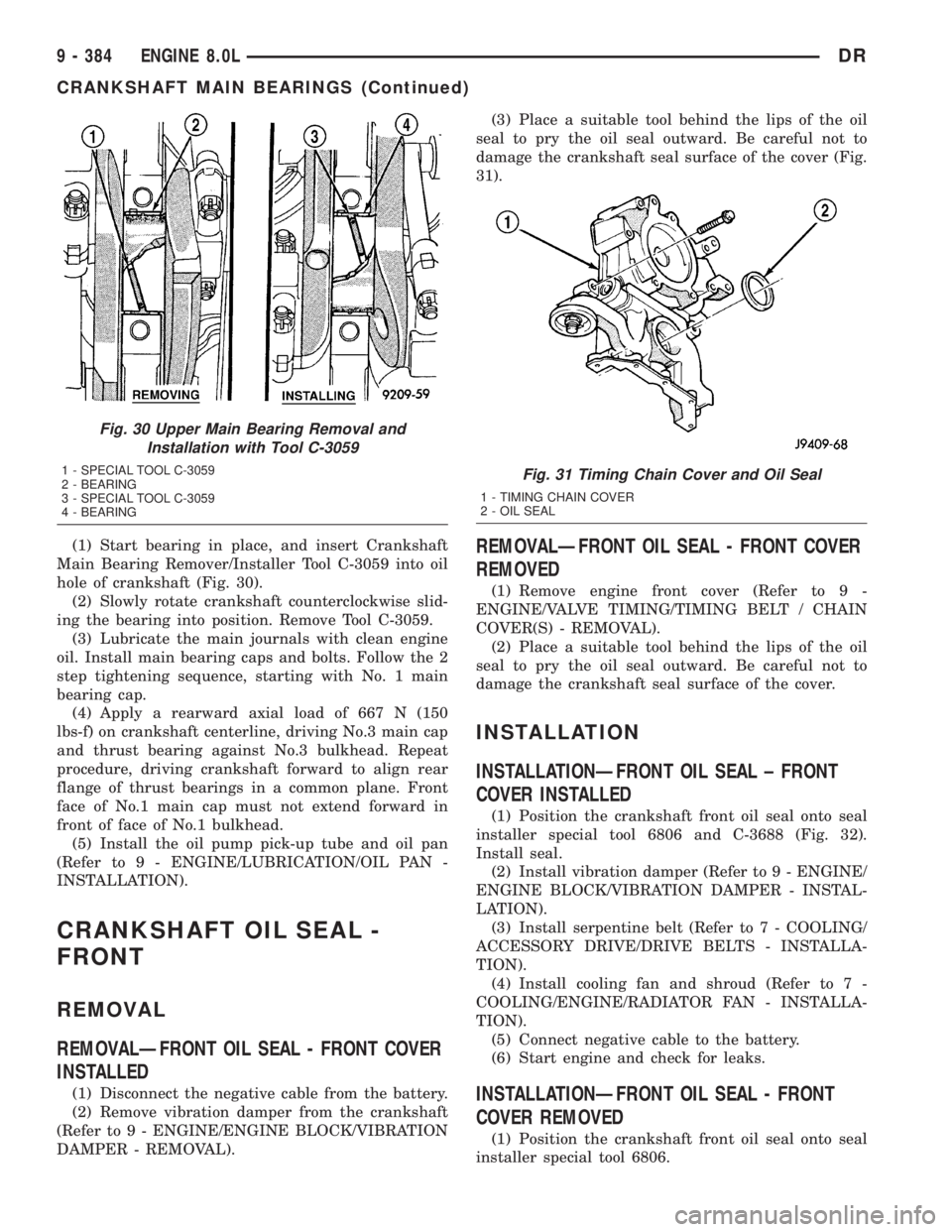
(1) Start bearing in place, and insert Crankshaft
Main Bearing Remover/Installer Tool C-3059 into oil
hole of crankshaft (Fig. 30).
(2) Slowly rotate crankshaft counterclockwise slid-
ing the bearing into position. Remove Tool C-3059.
(3) Lubricate the main journals with clean engine
oil. Install main bearing caps and bolts. Follow the 2
step tightening sequence, starting with No. 1 main
bearing cap.
(4) Apply a rearward axial load of 667 N (150
lbs-f) on crankshaft centerline, driving No.3 main cap
and thrust bearing against No.3 bulkhead. Repeat
procedure, driving crankshaft forward to align rear
flange of thrust bearings in a common plane. Front
face of No.1 main cap must not extend forward in
front of face of No.1 bulkhead.
(5) Install the oil pump pick-up tube and oil pan
(Refer to 9 - ENGINE/LUBRICATION/OIL PAN -
INSTALLATION).
CRANKSHAFT OIL SEAL -
FRONT
REMOVAL
REMOVALÐFRONT OIL SEAL - FRONT COVER
INSTALLED
(1) Disconnect the negative cable from the battery.
(2) Remove vibration damper from the crankshaft
(Refer to 9 - ENGINE/ENGINE BLOCK/VIBRATION
DAMPER - REMOVAL).(3) Place a suitable tool behind the lips of the oil
seal to pry the oil seal outward. Be careful not to
damage the crankshaft seal surface of the cover (Fig.
31).
REMOVALÐFRONT OIL SEAL - FRONT COVER
REMOVED
(1) Remove engine front cover (Refer to 9 -
ENGINE/VALVE TIMING/TIMING BELT / CHAIN
COVER(S) - REMOVAL).
(2) Place a suitable tool behind the lips of the oil
seal to pry the oil seal outward. Be careful not to
damage the crankshaft seal surface of the cover.
INSTALLATION
INSTALLATIONÐFRONT OIL SEAL ± FRONT
COVER INSTALLED
(1) Position the crankshaft front oil seal onto seal
installer special tool 6806 and C-3688 (Fig. 32).
Install seal.
(2) Install vibration damper (Refer to 9 - ENGINE/
ENGINE BLOCK/VIBRATION DAMPER - INSTAL-
LATION).
(3) Install serpentine belt (Refer to 7 - COOLING/
ACCESSORY DRIVE/DRIVE BELTS - INSTALLA-
TION).
(4) Install cooling fan and shroud (Refer to 7 -
COOLING/ENGINE/RADIATOR FAN - INSTALLA-
TION).
(5) Connect negative cable to the battery.
(6) Start engine and check for leaks.
INSTALLATIONÐFRONT OIL SEAL - FRONT
COVER REMOVED
(1) Position the crankshaft front oil seal onto seal
installer special tool 6806.
Fig. 30 Upper Main Bearing Removal and
Installation with Tool C-3059
1 - SPECIAL TOOL C-3059
2 - BEARING
3 - SPECIAL TOOL C-3059
4 - BEARINGFig. 31 Timing Chain Cover and Oil Seal
1 - TIMING CHAIN COVER
2 - OIL SEAL
9 - 384 ENGINE 8.0LDR
CRANKSHAFT MAIN BEARINGS (Continued)