2003 DODGE RAM belt
[x] Cancel search: beltPage 1527 of 2895
(5) Assemble exhaust pipe to manifold and secure
with bolts, nuts and retainers. Tighten the bolts and
nuts to 34 N´m (25 ft. lbs.) torque.
(6) Lower the vehicle.
(7) Connect the negative cable to the battery.
TIMING BELT / CHAIN
COVER(S)
REMOVAL
(1) Disconnect the negative cable from the battery.
(2) Remove water pump (Refer to 7 - COOLING/
ENGINE/WATER PUMP - REMOVAL).
(3) Remove power steering pump (Refer to 19 -
STEERING/PUMP - REMOVAL).
(4) Remove vibration damper (Refer to 9 -
ENGINE/ENGINE BLOCK/VIBRATION DAMPER -
REMOVAL).
(5) Loosen oil pan bolts and remove the front bolt
at each side.
(6) Remove the cover bolts.
(7) Remove chain case cover and gasket using
extreme caution to avoid damaging oil pan gasket.
INSTALLATION
(1) Be sure mating surfaces of chain case cover
and cylinder block are clean and free from burrs.
(2) The water pump mounting surface must be
cleaned.
(3) Using a new cover gasket, carefully install
chain case cover to avoid damaging oil pan gasket.
Use a small amount of MopartSilicone Rubber Adhe-
sive Sealant, or equivalent, at the joint between tim-
ing chain cover gasket and the oil pan gasket. Finger
tighten the timing chain cover bolts at this time.NOTE: Special Tool 6635 must be used to align the
front cover and seal with the crankshaft.
(4) Position the special tool 6635 onto the crank-
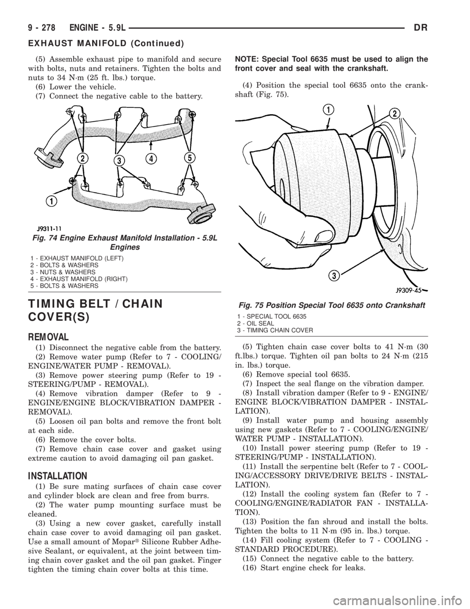
shaft (Fig. 75).
(5) Tighten chain case cover bolts to 41 N´m (30
ft.lbs.) torque. Tighten oil pan bolts to 24 N´m (215
in. lbs.) torque.
(6) Remove special tool 6635.
(7)
Inspect the seal flange on the vibration damper.
(8) Install vibration damper (Refer to 9 - ENGINE/
ENGINE BLOCK/VIBRATION DAMPER - INSTAL-
LATION).
(9) Install water pump and housing assembly
using new gaskets (Refer to 7 - COOLING/ENGINE/
WATER PUMP - INSTALLATION).
(10) Install power steering pump (Refer to 19 -
STEERING/PUMP - INSTALLATION).
(11) Install the serpentine belt (Refer to 7 - COOL-
ING/ACCESSORY DRIVE/DRIVE BELTS - INSTAL-
LATION).
(12) Install the cooling system fan (Refer to 7 -
COOLING/ENGINE/RADIATOR FAN - INSTALLA-
TION).
(13) Position the fan shroud and install the bolts.
Tighten the bolts to 11 N´m (95 in. lbs.) torque.
(14) Fill cooling system (Refer to 7 - COOLING -
STANDARD PROCEDURE).
(15) Connect the negative cable to the battery.
(16) Start engine check for leaks.
Fig. 74 Engine Exhaust Manifold Installation - 5.9L
Engines
1 - EXHAUST MANIFOLD (LEFT)
2 - BOLTS & WASHERS
3 - NUTS & WASHERS
4 - EXHAUST MANIFOLD (RIGHT)
5 - BOLTS & WASHERS
Fig. 75 Position Special Tool 6635 onto Crankshaft
1 - SPECIAL TOOL 6635
2 - OIL SEAL
3 - TIMING CHAIN COVER
9 - 278 ENGINE - 5.9LDR
EXHAUST MANIFOLD (Continued)
Page 1528 of 2895
TIMING BELT/CHAIN AND
SPROCKETS
REMOVAL
(1) Disconnect battery negative cable.
(2) Remove Timing Chain Cover (Refer to 9 -
ENGINE/VALVE TIMING/TIMING BELT / CHAIN
COVER(S) - REMOVAL).
(3) Re-install the vibration damper bolt finger
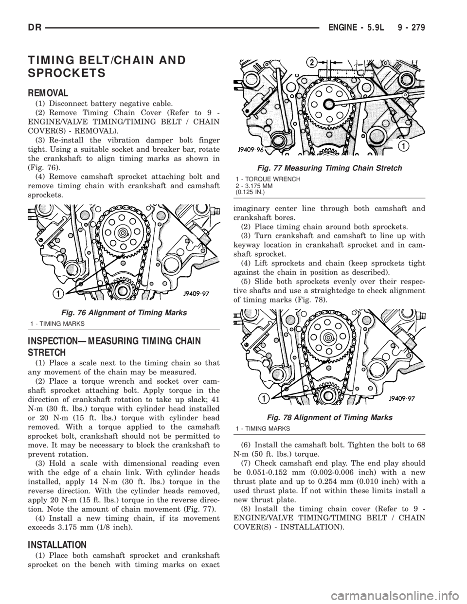
tight. Using a suitable socket and breaker bar, rotate
the crankshaft to align timing marks as shown in
(Fig. 76).
(4) Remove camshaft sprocket attaching bolt and
remove timing chain with crankshaft and camshaft
sprockets.
INSPECTIONÐMEASURING TIMING CHAIN
STRETCH
(1) Place a scale next to the timing chain so that
any movement of the chain may be measured.
(2) Place a torque wrench and socket over cam-
shaft sprocket attaching bolt. Apply torque in the
direction of crankshaft rotation to take up slack; 41
N´m (30 ft. lbs.) torque with cylinder head installed
or 20 N´m (15 ft. lbs.) torque with cylinder head
removed. With a torque applied to the camshaft
sprocket bolt, crankshaft should not be permitted to
move. It may be necessary to block the crankshaft to
prevent rotation.
(3) Hold a scale with dimensional reading even
with the edge of a chain link. With cylinder heads
installed, apply 14 N´m (30 ft. lbs.) torque in the
reverse direction. With the cylinder heads removed,
apply 20 N´m (15 ft. lbs.) torque in the reverse direc-
tion. Note the amount of chain movement (Fig. 77).
(4) Install a new timing chain, if its movement
exceeds 3.175 mm (1/8 inch).
INSTALLATION
(1) Place both camshaft sprocket and crankshaft
sprocket on the bench with timing marks on exactimaginary center line through both camshaft and
crankshaft bores.
(2) Place timing chain around both sprockets.
(3) Turn crankshaft and camshaft to line up with
keyway location in crankshaft sprocket and in cam-
shaft sprocket.
(4) Lift sprockets and chain (keep sprockets tight
against the chain in position as described).
(5) Slide both sprockets evenly over their respec-
tive shafts and use a straightedge to check alignment
of timing marks (Fig. 78).
(6) Install the camshaft bolt. Tighten the bolt to 68
N´m (50 ft. lbs.) torque.
(7) Check camshaft end play. The end play should
be 0.051-0.152 mm (0.002-0.006 inch) with a new
thrust plate and up to 0.254 mm (0.010 inch) with a
used thrust plate. If not within these limits install a
new thrust plate.
(8) Install the timing chain cover (Refer to 9 -
ENGINE/VALVE TIMING/TIMING BELT / CHAIN
COVER(S) - INSTALLATION).
Fig. 76 Alignment of Timing Marks
1 - TIMING MARKS
Fig. 77 Measuring Timing Chain Stretch
1 - TORQUE WRENCH
2 - 3.175 MM
(0.125 IN.)
Fig. 78 Alignment of Timing Marks
1 - TIMING MARKS
DRENGINE - 5.9L 9 - 279
Page 1533 of 2895
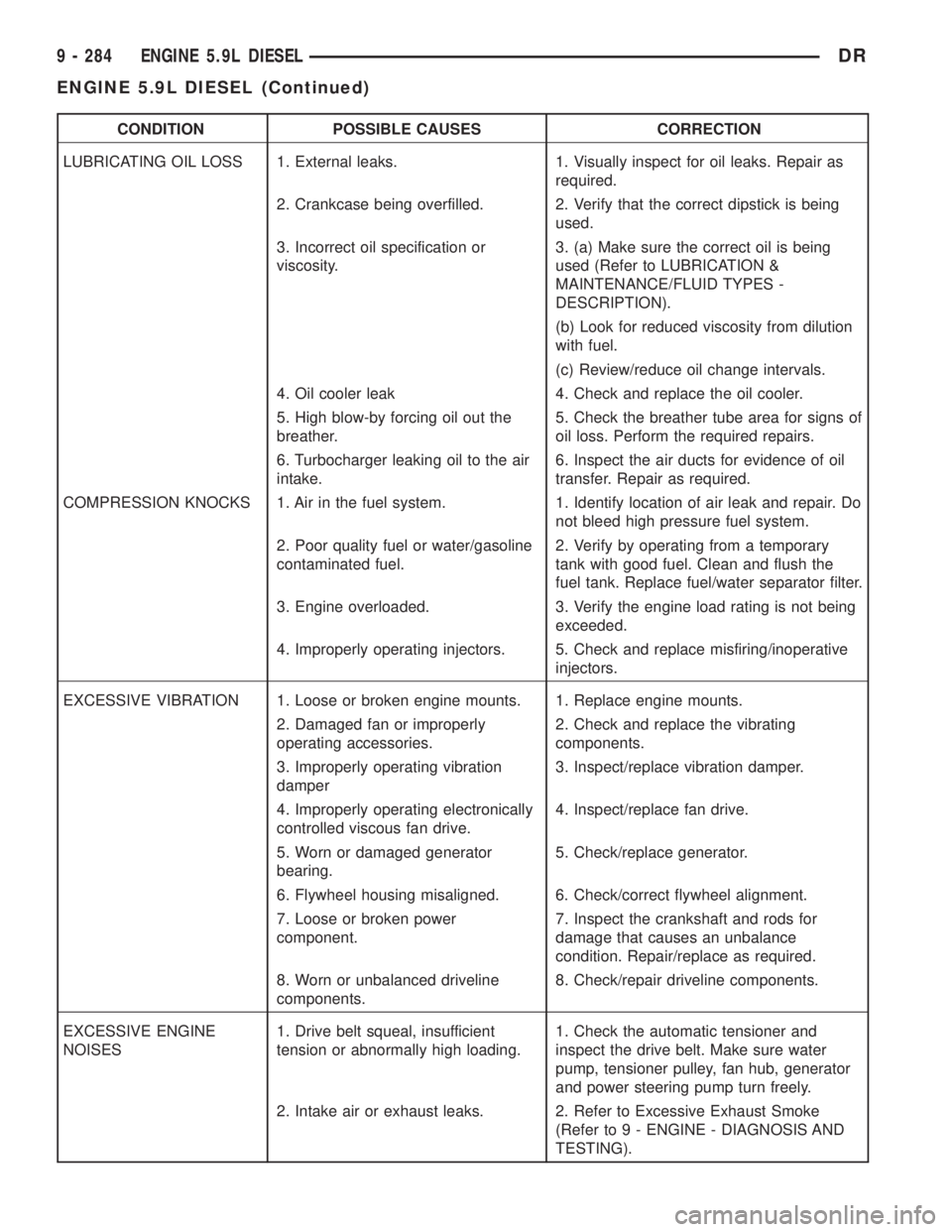
CONDITION POSSIBLE CAUSES CORRECTION
LUBRICATING OIL LOSS 1. External leaks. 1. Visually inspect for oil leaks. Repair as
required.
2. Crankcase being overfilled. 2. Verify that the correct dipstick is being
used.
3. Incorrect oil specification or
viscosity.3. (a) Make sure the correct oil is being
used (Refer to LUBRICATION &
MAINTENANCE/FLUID TYPES -
DESCRIPTION).
(b) Look for reduced viscosity from dilution
with fuel.
(c) Review/reduce oil change intervals.
4. Oil cooler leak 4. Check and replace the oil cooler.
5. High blow-by forcing oil out the
breather.5. Check the breather tube area for signs of
oil loss. Perform the required repairs.
6. Turbocharger leaking oil to the air
intake.6. Inspect the air ducts for evidence of oil
transfer. Repair as required.
COMPRESSION KNOCKS 1. Air in the fuel system. 1. Identify location of air leak and repair. Do
not bleed high pressure fuel system.
2. Poor quality fuel or water/gasoline
contaminated fuel.2. Verify by operating from a temporary
tank with good fuel. Clean and flush the
fuel tank. Replace fuel/water separator filter.
3. Engine overloaded. 3. Verify the engine load rating is not being
exceeded.
4. Improperly operating injectors. 5. Check and replace misfiring/inoperative
injectors.
EXCESSIVE VIBRATION 1. Loose or broken engine mounts. 1. Replace engine mounts.
2. Damaged fan or improperly
operating accessories.2. Check and replace the vibrating
components.
3. Improperly operating vibration
damper3. Inspect/replace vibration damper.
4. Improperly operating electronically
controlled viscous fan drive.4. Inspect/replace fan drive.
5. Worn or damaged generator
bearing.5. Check/replace generator.
6. Flywheel housing misaligned. 6. Check/correct flywheel alignment.
7. Loose or broken power
component.7. Inspect the crankshaft and rods for
damage that causes an unbalance
condition. Repair/replace as required.
8. Worn or unbalanced driveline
components.8. Check/repair driveline components.
EXCESSIVE ENGINE
NOISES1. Drive belt squeal, insufficient
tension or abnormally high loading.1. Check the automatic tensioner and
inspect the drive belt. Make sure water
pump, tensioner pulley, fan hub, generator
and power steering pump turn freely.
2. Intake air or exhaust leaks. 2. Refer to Excessive Exhaust Smoke
(Refer to 9 - ENGINE - DIAGNOSIS AND
TESTING).
9 - 284 ENGINE 5.9L DIESELDR
ENGINE 5.9L DIESEL (Continued)
Page 1547 of 2895
Filter Removal
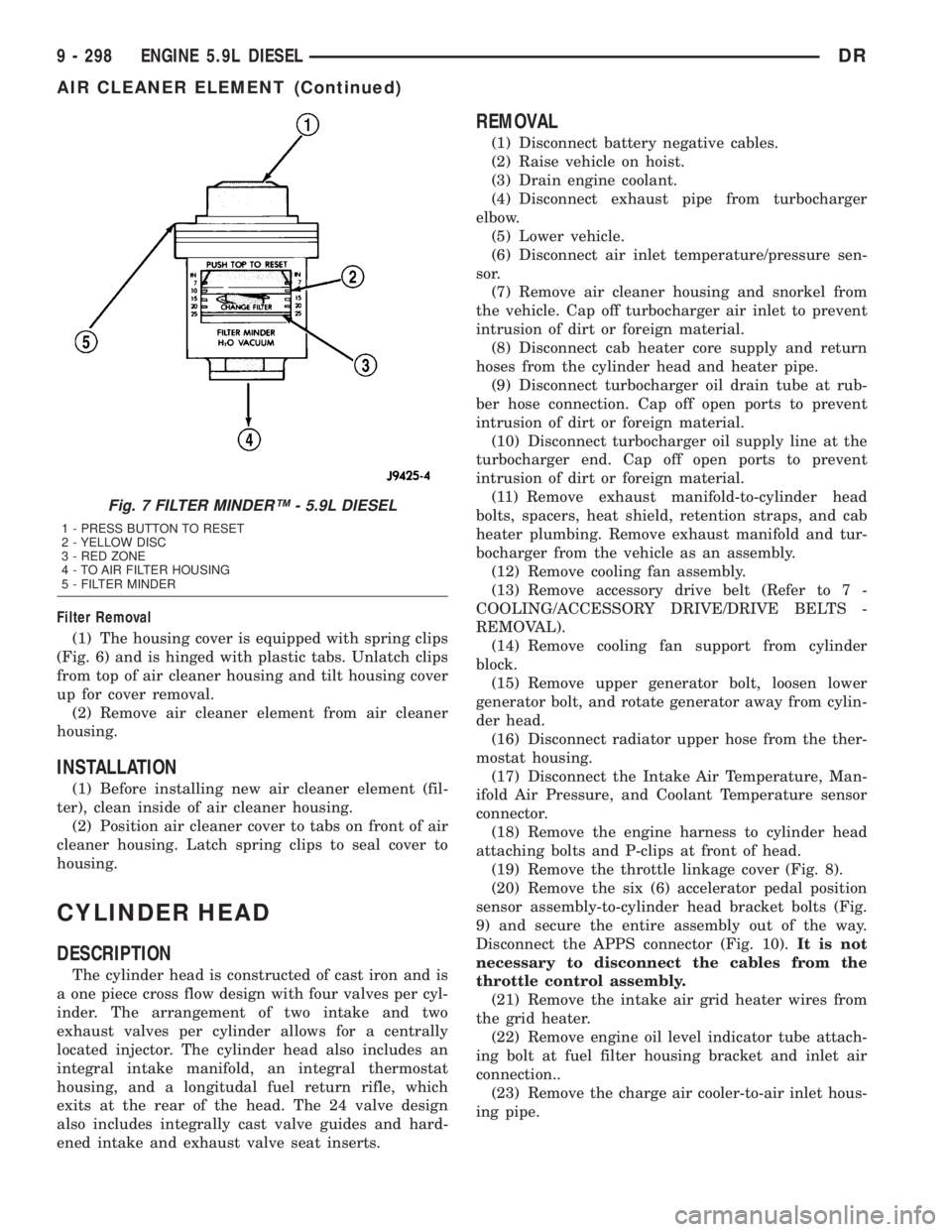
(1) The housing cover is equipped with spring clips
(Fig. 6) and is hinged with plastic tabs. Unlatch clips
from top of air cleaner housing and tilt housing cover
up for cover removal.
(2) Remove air cleaner element from air cleaner
housing.
INSTALLATION
(1) Before installing new air cleaner element (fil-
ter), clean inside of air cleaner housing.
(2) Position air cleaner cover to tabs on front of air
cleaner housing. Latch spring clips to seal cover to
housing.
CYLINDER HEAD
DESCRIPTION
The cylinder head is constructed of cast iron and is
a one piece cross flow design with four valves per cyl-
inder. The arrangement of two intake and two
exhaust valves per cylinder allows for a centrally
located injector. The cylinder head also includes an
integral intake manifold, an integral thermostat
housing, and a longitudal fuel return rifle, which
exits at the rear of the head. The 24 valve design
also includes integrally cast valve guides and hard-
ened intake and exhaust valve seat inserts.
REMOVAL
(1) Disconnect battery negative cables.
(2) Raise vehicle on hoist.
(3) Drain engine coolant.
(4) Disconnect exhaust pipe from turbocharger
elbow.
(5) Lower vehicle.
(6) Disconnect air inlet temperature/pressure sen-
sor.
(7) Remove air cleaner housing and snorkel from
the vehicle. Cap off turbocharger air inlet to prevent
intrusion of dirt or foreign material.
(8) Disconnect cab heater core supply and return
hoses from the cylinder head and heater pipe.
(9) Disconnect turbocharger oil drain tube at rub-
ber hose connection. Cap off open ports to prevent
intrusion of dirt or foreign material.
(10) Disconnect turbocharger oil supply line at the
turbocharger end. Cap off open ports to prevent
intrusion of dirt or foreign material.
(11) Remove exhaust manifold-to-cylinder head
bolts, spacers, heat shield, retention straps, and cab
heater plumbing. Remove exhaust manifold and tur-
bocharger from the vehicle as an assembly.
(12) Remove cooling fan assembly.
(13) Remove accessory drive belt (Refer to 7 -
COOLING/ACCESSORY DRIVE/DRIVE BELTS -
REMOVAL).
(14) Remove cooling fan support from cylinder
block.
(15) Remove upper generator bolt, loosen lower
generator bolt, and rotate generator away from cylin-
der head.
(16) Disconnect radiator upper hose from the ther-
mostat housing.
(17) Disconnect the Intake Air Temperature, Man-
ifold Air Pressure, and Coolant Temperature sensor
connector.
(18) Remove the engine harness to cylinder head
attaching bolts and P-clips at front of head.
(19) Remove the throttle linkage cover (Fig. 8).
(20) Remove the six (6) accelerator pedal position
sensor assembly-to-cylinder head bracket bolts (Fig.
9) and secure the entire assembly out of the way.
Disconnect the APPS connector (Fig. 10).It is not
necessary to disconnect the cables from the
throttle control assembly.
(21) Remove the intake air grid heater wires from
the grid heater.
(22) Remove engine oil level indicator tube attach-
ing bolt at fuel filter housing bracket and inlet air
connection..
(23) Remove the charge air cooler-to-air inlet hous-
ing pipe.
Fig. 7 FILTER MINDERŸ - 5.9L DIESEL
1 - PRESS BUTTON TO RESET
2 - YELLOW DISC
3 - RED ZONE
4 - TO AIR FILTER HOUSING
5 - FILTER MINDER
9 - 298 ENGINE 5.9L DIESELDR
AIR CLEANER ELEMENT (Continued)
Page 1553 of 2895
(40) Install wire harness P-clip to top of bracket.
(41) Install fan support and torque to 32 N´m (24
ft. lbs.).
(42) Install cooling fan/drive and torque to 33 N´m
(24 ft. lbs.).
(43) Install accessory drive belt (Refer to 7 -
COOLING/ACCESSORY DRIVE/DRIVE BELTS -
INSTALLATION).
(44) Install exhaust manifold/turbocharger assem-
bly, using new gaskets. Start all bolts/spacers by
hand. Torque bolts to 43 N´m (32 ft. lbs.).
(45) Install exhaust manifold heat shield. Torque
to 24 N´m (18 ft. lbs.).
(46) Install exhaust bolt retention straps across
cylinders5&6.
(47) Connect turbocharger oil drain tube. Torque to
8 N´m (71 in. lbs.).
(48) Perform the turbocharger pre-lube procedure.
Refer to Group 11, Exhaust System and Turbo-
charger for the correct procedure.
(49) Connect the turbocharger oil supply line.
Torque to 24 N´m (18 ft. lbs.).
(50) Install air cleaner housing and duct.
(51) Connect air inlet temperature/pressure sensor.
(52) Raise vehicle on hoist.
(53) Install exhaust pipe to turbocharger elbow.
Torque bolts to 8 N´m (72 in. lbs.).
(54) Lower vehicle.
(55) Fill engine coolant (Refer to 7 - COOLING -
STANDARD PROCEDURE).
(56) Start engine and check for leaks.
CYLINDER HEAD COVER(S)
REMOVAL
REMOVALÐCYLINDER HEAD COVER
(1) Disconnect both battery negative cables.
(2) Remove oil fill cap.
(3) Remove the breather cover.
(4) Disconnect the breather hose and breather
drain tube from the breather housing.
(5) Remove cylinder head cover bolts.
(6) Remove the cylinder head cover.
REMOVALÐROCKER HOUSING
(1) Remove cylinder head cover as outlined in this
section.
(2) Disconnect rocker housing injector harness con-
nectors.
(3) Remove injector harness nuts from injectors.
(4) Remove rocker housing bolts.
(5) Remove rocker housing and gasket.
CLEANING
Using a suitable solvent, Clean and dry gasket
mating surfaces on cylinder head and rocker housing.
Wipe gasket dry and inspect for re-use.
INSPECTION
The cylinder head cover gasket, rocker hous-
ing gasket, are reusable.However, should cracks,
nicks, or tears be present in the rubber/silicone con-
struction, the defective components should be
replaced. Also replace gasket if it is no longer flexi-
ble. Inspect o-rings on cylinder head cover bolts.
INSTALLATION
INSTALLATIONÐCYLINDER HEAD COVER
(1) Inspect cylinder head cover gasket for cuts and
proper installation in groove. Replace if damaged.
(2) Position cylinder cover on top of rocker hous-
ing.
(3) Install bolts.
(4) Starting with the center bolt, torque to 24 N´m
(18 ft. lbs.).
(5) Install breather hose to breather.
(6) Install breather drain hose to breather.
(7) Install breather cover and wire harness clip.
Torque to 24 N´m (18 ft. lbs.).
INSTALLATIONÐROCKER HOUSING
(1) Inspect rocker housing gasket for cuts, nicks,
or tears. Replace if damaged or if gasket has come
out of groove.
(2) Inspect rocker housing gasket for proper instal-
lation in groove. Gasket bead must be centered in
groove. A gasket bead that is tilted to the side will
cause an oil leak.
(3) Install ToolXXXXguide pins (or equivalent)
into the cylinder head at rocker housing bolt loca-
tions #1 and #5.
(4) Install the rocker hoiusing over the guide pins.
Carefully gyide the rocker housing evenly down onto
the cylinder head.
(5) With guide pins in place, install remaining
rocker housing bolts and tighten finger tight.
(6) Remove guide pins and install remaining
rocker housing bolts finger tight.
(7) Install rocker housing and bolts. Torque bolts,
working from center out, to 24 Nm (18ft. lbs.).
(8) Install injector harness nuts to injector sole-
noid. Torque to 1.5 Nm (13 in. lbs.).
(9) Connect rocker housing injector harness con-
nections.
9 - 304 ENGINE 5.9L DIESELDR
CYLINDER HEAD (Continued)
Page 1558 of 2895
mark in the 12 o'clock position.At this engine posi-
tion, cylinders #1 and #6 can be serviced.
(8) Remove the accessory drive belt (Refer to 7 -
COOLING/ACCESSORY DRIVE/DRIVE BELTS -
REMOVAL).
(9) With the damper TDC mark in the 12 o'clock
position, add a paint mark anywhere on the gear
housing cover next to the crankshaft damper. Place
another mark on the vibration damper in alignment
with the mark you just made on the cover.
(10) Divide the crankshaft damper into three
equally sized segments as follows:
(a) Using a tape measure, measure the circum-
ference of the crankshaft damper and divide the
measurement by three (3).
(b) Measure that distance in a counter-clockwise
direction from the first balancer mark and place
another mark on the balancer.
(c) From the second damper mark, again mea-
sure in a counter-clockwise direction and place a
mark on the damper at the same distance you
measured when placing the second damper mark.
The damper should now be marked in three
equally spaced locations and the damper TDC
mark should be in the 12 o'clock position.
(d) Remove injectors, fuel lines, and high pres-
sure connectors for every cylinder that requires
repair.
(11) Compress the valve springs at cyls. #1 and #6
as follows:
(a) Remove bolts and injector hold-down clamp.
(b) Using miller special tool #9010, remove injec-
tor.
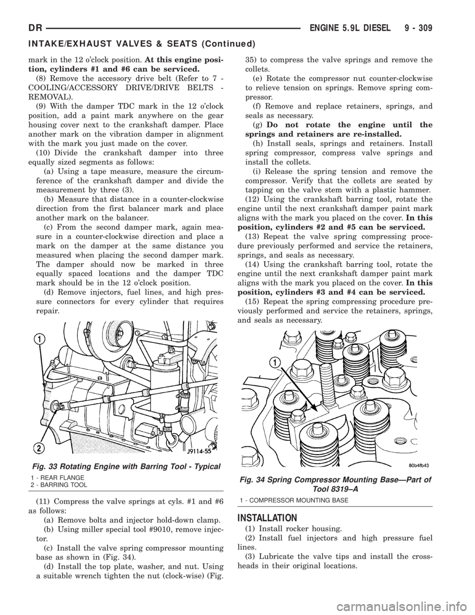
(c) Install the valve spring compressor mounting
base as shown in (Fig. 34).
(d) Install the top plate, washer, and nut. Using
a suitable wrench tighten the nut (clock-wise) (Fig.35) to compress the valve springs and remove the
collets.
(e) Rotate the compressor nut counter-clockwise
to relieve tension on springs. Remove spring com-
pressor.
(f) Remove and replace retainers, springs, and
seals as necessary.
(g)Do not rotate the engine until the
springs and retainers are re-installed.
(h) Install seals, springs and retainers. Install
spring compressor, compress valve springs and
install the collets.
(i) Release the spring tension and remove the
compressor. Verify that the collets are seated by
tapping on the valve stem with a plastic hammer.
(12) Using the crankshaft barring tool, rotate the
engine until the next crankshaft damper paint mark
aligns with the mark you placed on the cover.In this
position, cylinders #2 and #5 can be serviced.
(13) Repeat the valve spring compressing proce-
dure previously performed and service the retainers,
springs, and seals as necessary.
(14) Using the crankshaft barring tool, rotate the
engine until the next crankshaft damper paint mark
aligns with the mark you placed on the cover.In this
position, cylinders #3 and #4 can be serviced.
(15) Repeat the spring compressing procedure pre-
viously performed and service the retainers, springs,
and seals as necessary.
INSTALLATION
(1) Install rocker housing.
(2) Install fuel injectors and high pressure fuel
lines.
(3) Lubricate the valve tips and install the cross-
heads in their original locations.
Fig. 33 Rotating Engine with Barring Tool - Typical
1 - REAR FLANGE
2 - BARRING TOOLFig. 34 Spring Compressor Mounting BaseÐPart of
Tool 8319±A
1 - COMPRESSOR MOUNTING BASE
DRENGINE 5.9L DIESEL 9 - 309
INTAKE/EXHAUST VALVES & SEATS (Continued)
Page 1566 of 2895
CAMSHAFT & BEARINGS (IN
BLOCK)
REMOVAL
REMOVALÐCAMSHAFT BEARINGS
NOTE: Measure the diameter of each bore. If the
camshaft bore for the first or rear cam bushing is
worn beyond the limit, install a new service bush-
ing. Inspect the rest of the camshaft bores for dam-
age or excessive wear.If the bores without a
bushing are worn beyond the limit, the engine must
be removed for machining and installation of ser-
vice bushings. If badly worn, replace the cylinder
block.
(1) Remove the camshaft (Refer to 9 - ENGINE/
ENGINE BLOCK/CAMSHAFT & BEARINGS (IN
BLOCK) - REMOVAL).
(2) Remove the bushing from the No.1 bore and
No.7 using a universal cam bushing tool.
(3) Mark the cylinder block so you can align the oil
hole in the cylinder block with the oil hole in the
bushing.
REMOVAL - CAMSHAFT
(1) Disconnect both battery negative cables.
(2) Recover A/C refrigerant (if A/C equipped) (Refer
to 24 - HEATING & AIR CONDITIONING/PLUMB-
ING - STANDARD PROCEDURE).
(3) Raise vehicle on hoist.
(4) Drain engine coolant into container suitable for
re-use (Refer to 7 - COOLING - STANDARD PROCE-
DURE).
(5) Lower vehicle.
(6) Remove radiator upper hose.
(7) Remove viscous fan/drive assembly and fan
shroud (Refer to 7 - COOLING/ENGINE/RADIATOR
FAN - REMOVAL).
(8) Disconnect the coolant recovery bottle hose
from the radiator filler neck.
(9) Disconnect lower radiator hose from radiator
outlet.
(10)Automatic Transmission models:Discon-
nect transmission oil cooler lines from front of radia-
tor using Special Tool 6931 (unless equipped with
finger-release disconnect).
(11) Remove radiator mounting screws and lift
radiator out of engine compartment.
(12) Remove upper radiator support panel.
(13) If A/C equipped, disconnect A/C condenser
refrigerant lines.
(14) Disconnect charge air cooler piping from the
cooler inlet and outlet.(15) Remove the two charge air cooler mounting
bolts.
(16) Remove charge air cooler (and A/C condenser
if equipped) from vehicle.
(17) Remove accessory drive belt (Refer to 7 -
COOLING/ACCESSORY DRIVE/DRIVE BELTS -
REMOVAL).
(18) Remove accessory drive belt tensioner.
(19) Remove the fan support/hub assembly.
(20) Remove crankshaft damper and speed indica-
tor ring (Refer to 9 - ENGINE/ENGINE BLOCK/VI-
BRATION DAMPER - REMOVAL).
(21) Remove the gear cover-to-housing bolts and
gently pry the cover away from the housing, taking
care not to mar the sealing surfaces. Remove dust
seal with cover.
(22) Using Special Tool 7471±B Crankshaft Bar-
ring Tool, rotate the crankshaft to align the timing
marks on the crankshaft and the camshaft gears.
(23) Remove the cylinder head cover (Refer to 9 -
ENGINE/CYLINDER HEAD/CYLINDER HEAD
COVER(S) - REMOVAL).
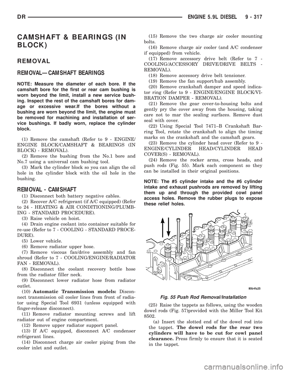
(24) Remove the rocker arms, cross heads, and
push rods (Fig. 55). Mark each component so they
can be installed in their original positions.
NOTE: The #5 cylinder intake and the #6 cylinder
intake and exhaust pushrods are removed by lifting
them up and through the provided cowl panel
access holes. Remove the rubber plugs to expose
these relief holes.
(25) Raise the tappets as follows, using the wooden
dowel rods (Fig. 57)provided with the Miller Tool Kit
8502.
(a) Insert the slotted end of the dowel rod into
the tappet.The dowel rods for the rear two
cylinders will have to be cut for cowl panel
clearance.Press firmly to ensure that it is seated
in the tappet.
Fig. 55 Push Rod Removal/Installation
DRENGINE 5.9L DIESEL 9 - 317
Page 1570 of 2895
(14) Install the fan support/hub assembly and
tighten bolts to 33 N´m (24 ft. lbs.) torque.
(15) Install the power steering pump.
(16) Install accessory drive belt tensioner. Torque
bolt to 43 Nm (43 ft. lbs.).
(17) Install the accessory drive belt (Refer to 7 -
COOLING/ACCESSORY DRIVE/DRIVE BELTS -
INSTALLATION).
(18) Install the charge air cooler (with a/c con-
denser and auxiliary transmission oil cooler, if
equipped) and tighten the mounting bolts to 2 N´m
(17 in. lbs.) torque.
(19) Connect charge air cooler inlet and outlet
pipes. Tighten clamps to 11 N´m (95 in. lbs.) torque.
(20) Install the radiator upper support panel.
(21) Close radiator petcock and lower the radiator
into the engine compartment. Tighten the mounting
bolts to 11 N´m (95 in. lbs.) torque.
(22) Raise vehicle on hoist.
(23)
Connect radiator lower hose and install clamp.
(24) Connect transmission auxiliary oil cooler lines
(if equipped).
(25) Lower vehicle.
(26) Install the fan shroud and tighten the mount-
ing screws to 6 N´m (50 in. lbs.) torque.
(27) Install the electronically controlled viscous
fan/drive assembly. Connect harness connector.(Refer
to 7 - COOLING/ENGINE/RADIATOR FAN -
INSTALLATION).
(28) Install the coolant recovery and windshield
washer fluid reservoirs to the fan shroud.
(29) Connect the coolant recovery hose to the radi-
ator filler neck.
(30) Add engine coolant (Refer to 7 - COOLING -
STANDARD PROCEDURE).
(31) Charge A/C system with refrigerant (if A/C
equipped) (Refer to 24 - HEATING & AIR CONDI-
TIONING/PLUMBING - STANDARD PROCEDURE).
(32) Connect the battery negative cables.
(33) Start engine and check for engine oil and cool-
ant leaks.
CONNECTING ROD BEARINGS
STANDARD PROCEDURE - CONNECTING ROD
BEARING AND CRANKSHAFT JOURNAL
CLEARANCE
(1) Measure the connecting rod bore with bearings
removedand the bolts tightened to 100 N´m (73 ft.
lbs.) torque..
(2) Measure the connecting rod bore with the bear-
ingsinstalledand the bolts tightened to 100 N´m
(73 ft. lbs.) torque.
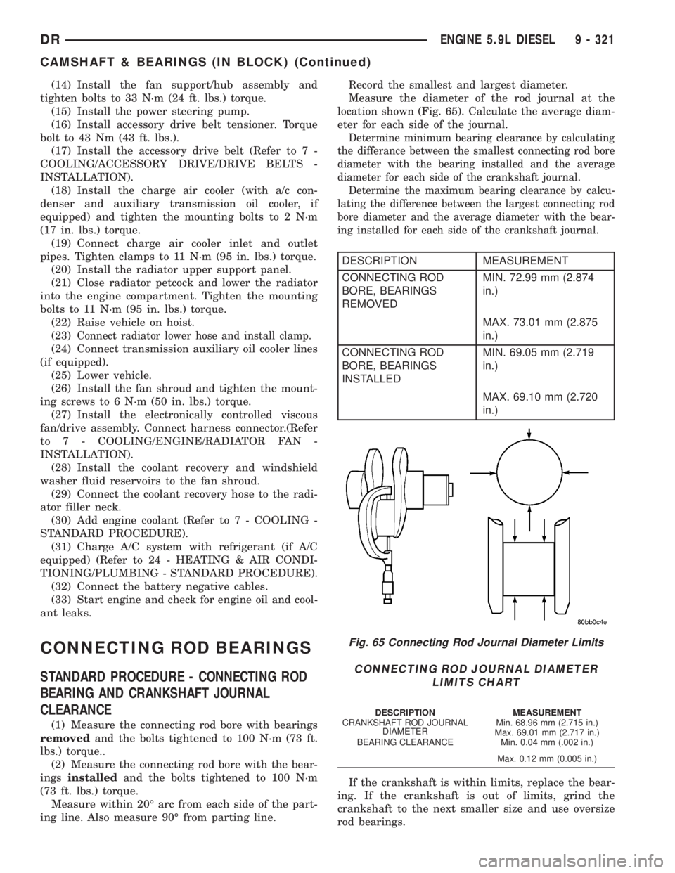
Measure within 20É arc from each side of the part-
ing line. Also measure 90É from parting line.Record the smallest and largest diameter.
Measure the diameter of the rod journal at the
location shown (Fig. 65). Calculate the average diam-
eter for each side of the journal.
Determine minimum bearing clearance by calculating
the differance between the smallest connecting rod bore
diameter with the bearing installed and the average
diameter for each side of the crankshaft journal.
Determine the maximum bearing clearance by calcu-
lating the difference between the largest connecting rod
bore diameter and the average diameter with the bear-
ing installed for each side of the crankshaft journal.
DESCRIPTION MEASUREMENT
CONNECTING ROD
BORE, BEARINGS
REMOVEDMIN. 72.99 mm (2.874
in.)
MAX. 73.01 mm (2.875
in.)
CONNECTING ROD
BORE, BEARINGS
INSTALLEDMIN. 69.05 mm (2.719
in.)
MAX. 69.10 mm (2.720
in.)
If the crankshaft is within limits, replace the bear-
ing. If the crankshaft is out of limits, grind the
crankshaft to the next smaller size and use oversize
rod bearings.
Fig. 65 Connecting Rod Journal Diameter Limits
CONNECTING ROD JOURNAL DIAMETER
LIMITS CHART
DESCRIPTION MEASUREMENT
CRANKSHAFT ROD JOURNAL
DIAMETERMin. 68.96 mm (2.715 in.)
Max. 69.01 mm (2.717 in.)
BEARING CLEARANCE Min. 0.04 mm (.002 in.)
Max. 0.12 mm (0.005 in.)
DRENGINE 5.9L DIESEL 9 - 321
CAMSHAFT & BEARINGS (IN BLOCK) (Continued)