2003 DODGE RAM steering
[x] Cancel search: steeringPage 2565 of 2895
TIRE CHAINS
Tire snow chains may be used oncertainmodels.
Refer to the Owner's Manual for more information.
DESCRIPTION - RADIAL ± PLY TIRES
Radial-ply tires improve handling, tread life and
ride quality, and decrease rolling resistance.
Radial-ply tires must always be used in sets of
four. Under no circumstances should they be used on
the front only. They may be mixed with temporary
spare tires when necessary. A maximum speed of 50
MPH is recommended while a temporary spare is in
use.
Radial-ply tires have the same load-carrying capac-
ity as other types of tires of the same size. They also
use the same recommended inflation pressures.
The use of oversized tires, either in the front or
rear of the vehicle, can cause vehicle drive train fail-
ure. This could also cause inaccurate wheel speed
signals when the vehicle is equipped with Anti-Lock
Brakes.
The use of tires from different manufactures on the
same vehicle is NOT recommended. The proper tire
pressure should be maintained on all four tires.
DESCRIPTION - TIRE PRESSURE FOR HIGH
SPEEDS
Where speed limits allow the vehicle to be driven at
high speeds, correct tire inflation pressure is very
important. For speeds up to and including 120 km/h (75
mph), tires must be inflated to the pressures shown on
the tire placard. For continuous speeds in excess of 120
km/h (75 mph), tires must be inflated to the maximum
pressure specified on the tire sidewall.
Vehicles loaded to the maximum capacity should not
be driven at continuous speeds above 75 mph (120
km/h).
For emergency vehicles that are driven at speeds
over 90 mph (144 km/h), special high speed tires
must be used. Consult tire manufacturer for correct
inflation pressure recommendations.
DESCRIPTION - REPLACEMENT TIRES
The original equipment tires provide a proper bal-
ance of many characteristics such as:
²Ride
²Noise
²Handling
²Durability
²Tread life
²Traction
²Rolling resistance
²Speed capability
It is recommended that tires equivalent to the orig-
inal equipment tires be used when replacement is
needed.
Failure to use equivalent replacement tires may
adversely affect the safety and handling of the vehicle.
The use of oversize tires may cause interference
with vehicle components. Under extremes of suspen-
sion and steering travel, interference with vehicle
components may cause tire damage.
WARNING: FAILURE TO EQUIP THE VEHICLE WITH
TIRES HAVING ADEQUATE SPEED CAPABILITY
CAN RESULT IN SUDDEN TIRE FAILURE.
DESCRIPTION - TIRE INFLATION PRESSURES
Under inflation will cause rapid shoulder wear, tire
flexing, and possible tire failure (Fig. 12).
Over inflation will cause rapid center wear and
loss of the tire's ability to cushion shocks (Fig. 13).
Improper inflation can cause:
²Uneven wear patterns
²Reduced tread life
²Reduced fuel economy
²Unsatisfactory ride
²Vehicle drift
For proper tire pressure specification refer to the Tire
Inflation Pressure Chart provided with the vehicles
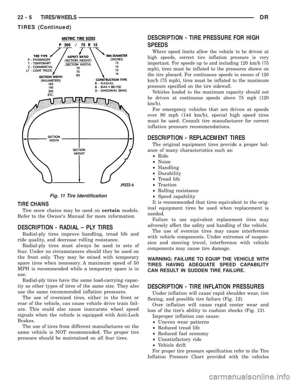
Fig. 11 Tire Identification
22 - 6 TIRES/WHEELSDR
TIRES (Continued)
Page 2580 of 2895
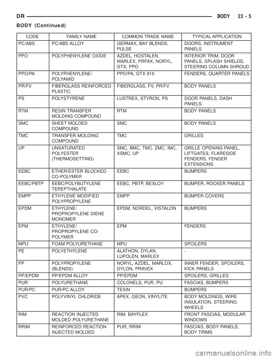
CODE FAMILY NAME COMMON TRADE NAME TYPICAL APPLICATION
PC/ABS PC/ABS ALLOY GERMAX, BAY BLENDS,
PULSEDOORS, INSTRUMENT
PANELS
PPO POLYPHENYLENE OXIDE AZDEL, HOSTALEN,
MARLEX, PRFAX, NORYL,
GTX, PPOINTERIOR TRIM, DOOR
PANELS, SPLASH SHIELDS,
STEERING COLUMN SHROUD
PPO/PA POLYPHENYLENE/
POLYAMIDPPO/PA, GTX 910 FENDERS, QUARTER PANELS
PR/FV FIBERGLASS REINFORCED
PLASTICFIBERGLASS, FV, PR/FV BODY PANELS
PS POLYSTYRENE LUSTREX, STYRON, PS DOOR PANELS, DASH
PANELS
RTM RESIN TRANSFER
MOLDING COMPOUNDRTM BODY PANELS
SMC SHEET MOLDED
COMPOUNDSMC BODY PANELS
TMC TRANSFER MOLDING
COMPOUNDTMC GRILLES
UP UNSATURATED
POLYESTER
(THERMOSETTING)SMC, BMC, TMC, ZMC, IMC,
XSMC, UPGRILLE OPENING PANEL,
LIFTGATES, FLARESIDE
FENDERS, FENDER
EXTENSIONS
EEBC ETHER/ESTER BLOCKED
CO-POLYMEREEBC BUMPERS
EEBC/PBTP EEBC/POLYBUTYLENE
TEREPTHALATEEEBC, PBTP, BEXLOY BUMPER, ROCKER PANELS
EMPP ETHYLENE MODIFIED
POLYPROPYLENEEMPP BUMPER COVERS
EPDM ETHYLENE/
PROPROPYLENE DIENE
MONOMEREPDM, NORDEL, VISTALON BUMPERS
EPM ETHYLENE/
PROPROPYLENE CO-
POLYMEREPM FENDERS
MPU FOAM POLYURETHANE MPU SPOILERS
PE POLYETHYLENE ALATHON, DYLAN,
LUPOLEN, MARLEX-
PP POLYPROPYLENE
(BLENDS)NORYL, AZDEL, MARLOX,
DYLON, PRAVEXINNER FENDER, SPOILERS,
KICK PANELS
PP/EPDM PP/EPDM ALLOY PP/EPDM SPOILERS, GRILLES
PUR POLYURETHANE COLONELS, PUR, PU FASCIAS, BUMPERS
PUR/PC PUR/PC ALLOY TEXIN BUMPERS
PVC POLYVINYL CHLORIDE APEX, GEON, VINYLITE BODY MOLDINGS, WIRE
INSULATION, STEERING
WHEELS
RIM REACTION INJECTED
MOLDED POLYURETHANERIM, BAYFLEX FRONT FASCIAS, MODULAR
WINDOWS
RRIM REINFORCED REACTION
INJECTED MOLDEDPUR, RRIM FASCIAS, BODY PANELS,
BODY TRIMS
DRBODY 23 - 5
BODY (Continued)
Page 2625 of 2895
INSTRUMENT PANEL
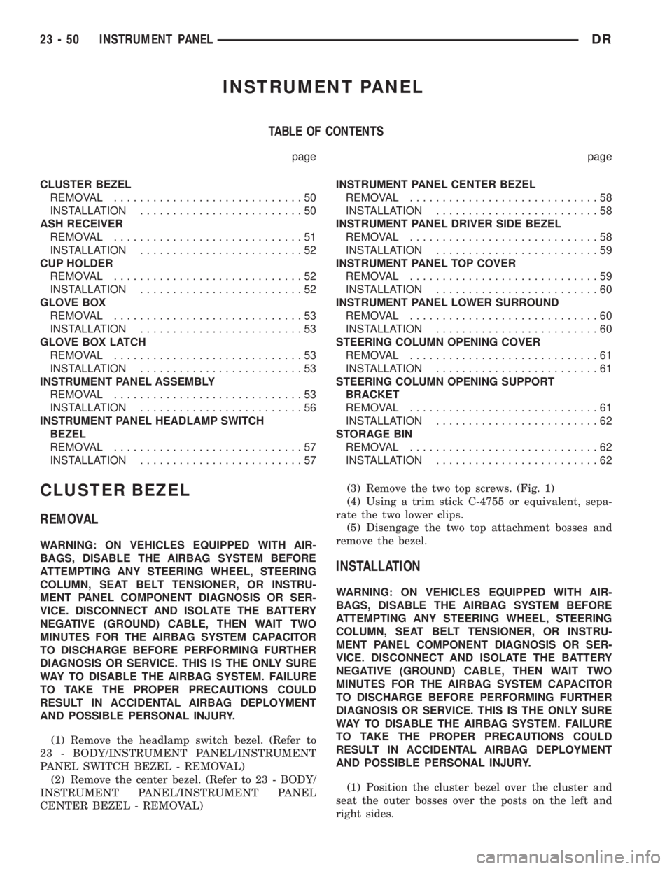
TABLE OF CONTENTS
page page
CLUSTER BEZEL
REMOVAL.............................50
INSTALLATION.........................50
ASH RECEIVER
REMOVAL.............................51
INSTALLATION.........................52
CUP HOLDER
REMOVAL.............................52
INSTALLATION.........................52
GLOVE BOX
REMOVAL.............................53
INSTALLATION.........................53
GLOVE BOX LATCH
REMOVAL.............................53
INSTALLATION.........................53
INSTRUMENT PANEL ASSEMBLY
REMOVAL.............................53
INSTALLATION.........................56
INSTRUMENT PANEL HEADLAMP SWITCH
BEZEL
REMOVAL.............................57
INSTALLATION.........................57INSTRUMENT PANEL CENTER BEZEL
REMOVAL.............................58
INSTALLATION.........................58
INSTRUMENT PANEL DRIVER SIDE BEZEL
REMOVAL.............................58
INSTALLATION.........................59
INSTRUMENT PANEL TOP COVER
REMOVAL.............................59
INSTALLATION.........................60
INSTRUMENT PANEL LOWER SURROUND
REMOVAL.............................60
INSTALLATION.........................60
STEERING COLUMN OPENING COVER
REMOVAL.............................61
INSTALLATION.........................61
STEERING COLUMN OPENING SUPPORT
BRACKET
REMOVAL.............................61
INSTALLATION.........................62
STORAGE BIN
REMOVAL.............................62
INSTALLATION.........................62
CLUSTER BEZEL
REMOVAL
WARNING: ON VEHICLES EQUIPPED WITH AIR-
BAGS, DISABLE THE AIRBAG SYSTEM BEFORE
ATTEMPTING ANY STEERING WHEEL, STEERING
COLUMN, SEAT BELT TENSIONER, OR INSTRU-
MENT PANEL COMPONENT DIAGNOSIS OR SER-
VICE. DISCONNECT AND ISOLATE THE BATTERY
NEGATIVE (GROUND) CABLE, THEN WAIT TWO
MINUTES FOR THE AIRBAG SYSTEM CAPACITOR
TO DISCHARGE BEFORE PERFORMING FURTHER
DIAGNOSIS OR SERVICE. THIS IS THE ONLY SURE
WAY TO DISABLE THE AIRBAG SYSTEM. FAILURE
TO TAKE THE PROPER PRECAUTIONS COULD
RESULT IN ACCIDENTAL AIRBAG DEPLOYMENT
AND POSSIBLE PERSONAL INJURY.
(1) Remove the headlamp switch bezel. (Refer to
23 - BODY/INSTRUMENT PANEL/INSTRUMENT
PANEL SWITCH BEZEL - REMOVAL)
(2) Remove the center bezel. (Refer to 23 - BODY/
INSTRUMENT PANEL/INSTRUMENT PANEL
CENTER BEZEL - REMOVAL)(3) Remove the two top screws. (Fig. 1)
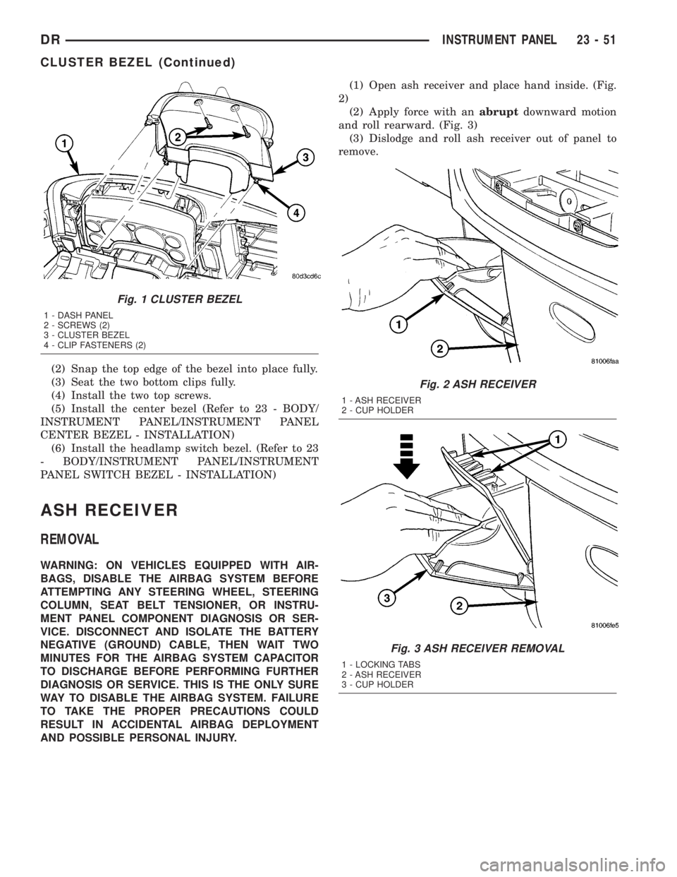
(4) Using a trim stick C-4755 or equivalent, sepa-
rate the two lower clips.
(5) Disengage the two top attachment bosses and
remove the bezel.
INSTALLATION
WARNING: ON VEHICLES EQUIPPED WITH AIR-
BAGS, DISABLE THE AIRBAG SYSTEM BEFORE
ATTEMPTING ANY STEERING WHEEL, STEERING
COLUMN, SEAT BELT TENSIONER, OR INSTRU-
MENT PANEL COMPONENT DIAGNOSIS OR SER-
VICE. DISCONNECT AND ISOLATE THE BATTERY
NEGATIVE (GROUND) CABLE, THEN WAIT TWO
MINUTES FOR THE AIRBAG SYSTEM CAPACITOR
TO DISCHARGE BEFORE PERFORMING FURTHER
DIAGNOSIS OR SERVICE. THIS IS THE ONLY SURE
WAY TO DISABLE THE AIRBAG SYSTEM. FAILURE
TO TAKE THE PROPER PRECAUTIONS COULD
RESULT IN ACCIDENTAL AIRBAG DEPLOYMENT
AND POSSIBLE PERSONAL INJURY.
(1) Position the cluster bezel over the cluster and
seat the outer bosses over the posts on the left and
right sides.
23 - 50 INSTRUMENT PANELDR
Page 2626 of 2895
(2) Snap the top edge of the bezel into place fully.
(3) Seat the two bottom clips fully.
(4) Install the two top screws.
(5) Install the center bezel (Refer to 23 - BODY/
INSTRUMENT PANEL/INSTRUMENT PANEL
CENTER BEZEL - INSTALLATION)
(6) Install the headlamp switch bezel. (Refer to 23
- BODY/INSTRUMENT PANEL/INSTRUMENT
PANEL SWITCH BEZEL - INSTALLATION)
ASH RECEIVER
REMOVAL
WARNING: ON VEHICLES EQUIPPED WITH AIR-
BAGS, DISABLE THE AIRBAG SYSTEM BEFORE
ATTEMPTING ANY STEERING WHEEL, STEERING
COLUMN, SEAT BELT TENSIONER, OR INSTRU-
MENT PANEL COMPONENT DIAGNOSIS OR SER-
VICE. DISCONNECT AND ISOLATE THE BATTERY
NEGATIVE (GROUND) CABLE, THEN WAIT TWO
MINUTES FOR THE AIRBAG SYSTEM CAPACITOR
TO DISCHARGE BEFORE PERFORMING FURTHER
DIAGNOSIS OR SERVICE. THIS IS THE ONLY SURE
WAY TO DISABLE THE AIRBAG SYSTEM. FAILURE
TO TAKE THE PROPER PRECAUTIONS COULD
RESULT IN ACCIDENTAL AIRBAG DEPLOYMENT
AND POSSIBLE PERSONAL INJURY.(1) Open ash receiver and place hand inside. (Fig.
2)
(2) Apply force with anabruptdownward motion
and roll rearward. (Fig. 3)
(3) Dislodge and roll ash receiver out of panel to
remove.
Fig. 1 CLUSTER BEZEL
1 - DASH PANEL
2 - SCREWS (2)
3 - CLUSTER BEZEL
4 - CLIP FASTENERS (2)
Fig. 2 ASH RECEIVER
1 - ASH RECEIVER
2 - CUP HOLDER
Fig. 3 ASH RECEIVER REMOVAL
1 - LOCKING TABS
2 - ASH RECEIVER
3 - CUP HOLDER
DRINSTRUMENT PANEL 23 - 51
CLUSTER BEZEL (Continued)
Page 2627 of 2895
INSTALLATION
WARNING: ON VEHICLES EQUIPPED WITH AIR-
BAGS, DISABLE THE AIRBAG SYSTEM BEFORE
ATTEMPTING ANY STEERING WHEEL, STEERING
COLUMN, SEAT BELT TENSIONER, OR INSTRU-
MENT PANEL COMPONENT DIAGNOSIS OR SER-
VICE. DISCONNECT AND ISOLATE THE BATTERY
NEGATIVE (GROUND) CABLE, THEN WAIT TWO
MINUTES FOR THE AIRBAG SYSTEM CAPACITOR
TO DISCHARGE BEFORE PERFORMING FURTHER
DIAGNOSIS OR SERVICE. THIS IS THE ONLY SURE
WAY TO DISABLE THE AIRBAG SYSTEM. FAILURE
TO TAKE THE PROPER PRECAUTIONS COULD
RESULT IN ACCIDENTAL AIRBAG DEPLOYMENT
AND POSSIBLE PERSONAL INJURY.
(1) Seat the bottom of the receiver into position.
(2) Pivot the receiver forward and seat the retain-
ing clips fully.
CUP HOLDER
REMOVAL
WARNING: ON VEHICLES EQUIPPED WITH AIR-
BAGS, DISABLE THE AIRBAG SYSTEM BEFORE
ATTEMPTING ANY STEERING WHEEL, STEERING
COLUMN, SEAT BELT TENSIONER, OR INSTRU-
MENT PANEL COMPONENT DIAGNOSIS OR SER-
VICE. DISCONNECT AND ISOLATE THE BATTERY
NEGATIVE (GROUND) CABLE, THEN WAIT TWO
MINUTES FOR THE AIRBAG SYSTEM CAPACITOR
TO DISCHARGE BEFORE PERFORMING FURTHER
DIAGNOSIS OR SERVICE. THIS IS THE ONLY SURE
WAY TO DISABLE THE AIRBAG SYSTEM. FAILURE
TO TAKE THE PROPER PRECAUTIONS COULD
RESULT IN ACCIDENTAL AIRBAG DEPLOYMENT
AND POSSIBLE PERSONAL INJURY.
(1) Remove the center bezel.(Refer to 23 - BODY/
INSTRUMENT PANEL/INSTRUMENT PANEL
CENTER BEZEL - REMOVAL)
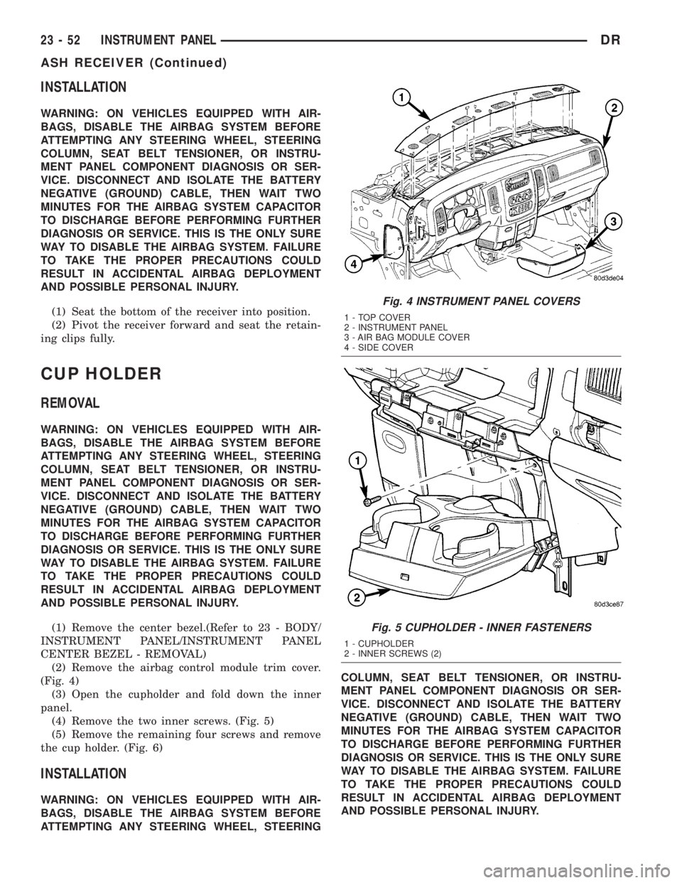
(2) Remove the airbag control module trim cover.
(Fig. 4)
(3) Open the cupholder and fold down the inner
panel.
(4) Remove the two inner screws. (Fig. 5)
(5) Remove the remaining four screws and remove
the cup holder. (Fig. 6)
INSTALLATION
WARNING: ON VEHICLES EQUIPPED WITH AIR-
BAGS, DISABLE THE AIRBAG SYSTEM BEFORE
ATTEMPTING ANY STEERING WHEEL, STEERINGCOLUMN, SEAT BELT TENSIONER, OR INSTRU-
MENT PANEL COMPONENT DIAGNOSIS OR SER-
VICE. DISCONNECT AND ISOLATE THE BATTERY
NEGATIVE (GROUND) CABLE, THEN WAIT TWO
MINUTES FOR THE AIRBAG SYSTEM CAPACITOR
TO DISCHARGE BEFORE PERFORMING FURTHER
DIAGNOSIS OR SERVICE. THIS IS THE ONLY SURE
WAY TO DISABLE THE AIRBAG SYSTEM. FAILURE
TO TAKE THE PROPER PRECAUTIONS COULD
RESULT IN ACCIDENTAL AIRBAG DEPLOYMENT
AND POSSIBLE PERSONAL INJURY.
Fig. 4 INSTRUMENT PANEL COVERS
1 - TOP COVER
2 - INSTRUMENT PANEL
3 - AIR BAG MODULE COVER
4 - SIDE COVER
Fig. 5 CUPHOLDER - INNER FASTENERS
1 - CUPHOLDER
2 - INNER SCREWS (2)
23 - 52 INSTRUMENT PANELDR
ASH RECEIVER (Continued)
Page 2628 of 2895
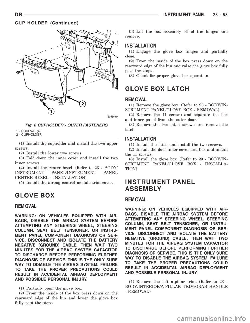
(1) Install the cupholder and install the two upper
screws.
(2) Install the lower two screws
(3) Fold down the inner cover and install the two
inner screws.
(4) Install the center bezel. (Refer to 23 - BODY/
INSTRUMENT PANEL/INSTRUMENT PANEL
CENTER BEZEL - INSTALLATION)
(5) Install the airbag control module trim cover.
GLOVE BOX
REMOVAL
WARNING: ON VEHICLES EQUIPPED WITH AIR-
BAGS, DISABLE THE AIRBAG SYSTEM BEFORE
ATTEMPTING ANY STEERING WHEEL, STEERING
COLUMN, SEAT BELT TENSIONER, OR INSTRU-
MENT PANEL COMPONENT DIAGNOSIS OR SER-
VICE. DISCONNECT AND ISOLATE THE BATTERY
NEGATIVE (GROUND) CABLE, THEN WAIT TWO
MINUTES FOR THE AIRBAG SYSTEM CAPACITOR
TO DISCHARGE BEFORE PERFORMING FURTHER
DIAGNOSIS OR SERVICE. THIS IS THE ONLY SURE
WAY TO DISABLE THE AIRBAG SYSTEM. FAILURE
TO TAKE THE PROPER PRECAUTIONS COULD
RESULT IN ACCIDENTAL AIRBAG DEPLOYMENT
AND POSSIBLE PERSONAL INJURY.
(1) Partially open the glove box.
(2) From the inside of the box press down on the
rearward edge of the bin and lower the glove box
fully past the stops.(3) Lift the box assembly off of the hinges and
remove.
INSTALLATION
(1) Engage the glove box hinges and partially
close.
(2) From the inside of the box press down on the
rearward edge of the bin and raise the glove box fully
past the stops.
(3) Check for proper glove box operation.
GLOVE BOX LATCH
REMOVAL
(1) Remove the glove box. (Refer to 23 - BODY/IN-
STRUMENT PANEL/GLOVE BOX - REMOVAL)
(2) Remove the 11 screws and separate the box
and inner panel from the outer door.
(3) Remove the two latch screws and remove the
latch.
INSTALLATION
(1) Install the latch and install the two screws.
(2) Install the door inner cover and box and install
the 11 screws.
(3) Install the glove box. (Refer to 23 - BODY/IN-
STRUMENT PANEL/GLOVE BOX - INSTALLA-
TION)
INSTRUMENT PANEL
ASSEMBLY
REMOVAL
WARNING: ON VEHICLES EQUIPPED WITH AIR-
BAGS, DISABLE THE AIRBAG SYSTEM BEFORE
ATTEMPTING ANY STEERING WHEEL, STEERING
COLUMN, SEAT BELT TENSIONER, OR INSTRU-
MENT PANEL COMPONENT DIAGNOSIS OR SER-
VICE. DISCONNECT AND ISOLATE THE BATTERY
NEGATIVE (GROUND) CABLE, THEN WAIT TWO
MINUTES FOR THE AIRBAG SYSTEM CAPACITOR
TO DISCHARGE BEFORE PERFORMING FURTHER
DIAGNOSIS OR SERVICE. THIS IS THE ONLY SURE
WAY TO DISABLE THE AIRBAG SYSTEM. FAILURE
TO TAKE THE PROPER PRECAUTIONS COULD
RESULT IN ACCIDENTAL AIRBAG DEPLOYMENT
AND POSSIBLE PERSONAL INJURY.
(1) Remove the left a-pillar trim. (Refer to 23 -
BODY/INTERIOR/A-PILLAR TRIM/GRAB HANDLE
- REMOVAL)
Fig. 6 CUPHOLDER - OUTER FASTENERS
1 - SCREWS (4)
2 - CUPHOLDER
DRINSTRUMENT PANEL 23 - 53
CUP HOLDER (Continued)
Page 2629 of 2895
(2) Remove the top cover. (Refer to 23 - BODY/IN-
STRUMENT PANEL/INSTRUMENT PANEL TOP
COVER - REMOVAL)
(3) Disconnect the headliner harness electrical con-
nector at the a-pillar.
(4) Using a trim stick C-4755 or equivalent, from
the notch on the bottom, remove the left side cover.
(Fig. 20)
(5) Remove the steering column. (Refer to 19 -
STEERING/COLUMN - REMOVAL)
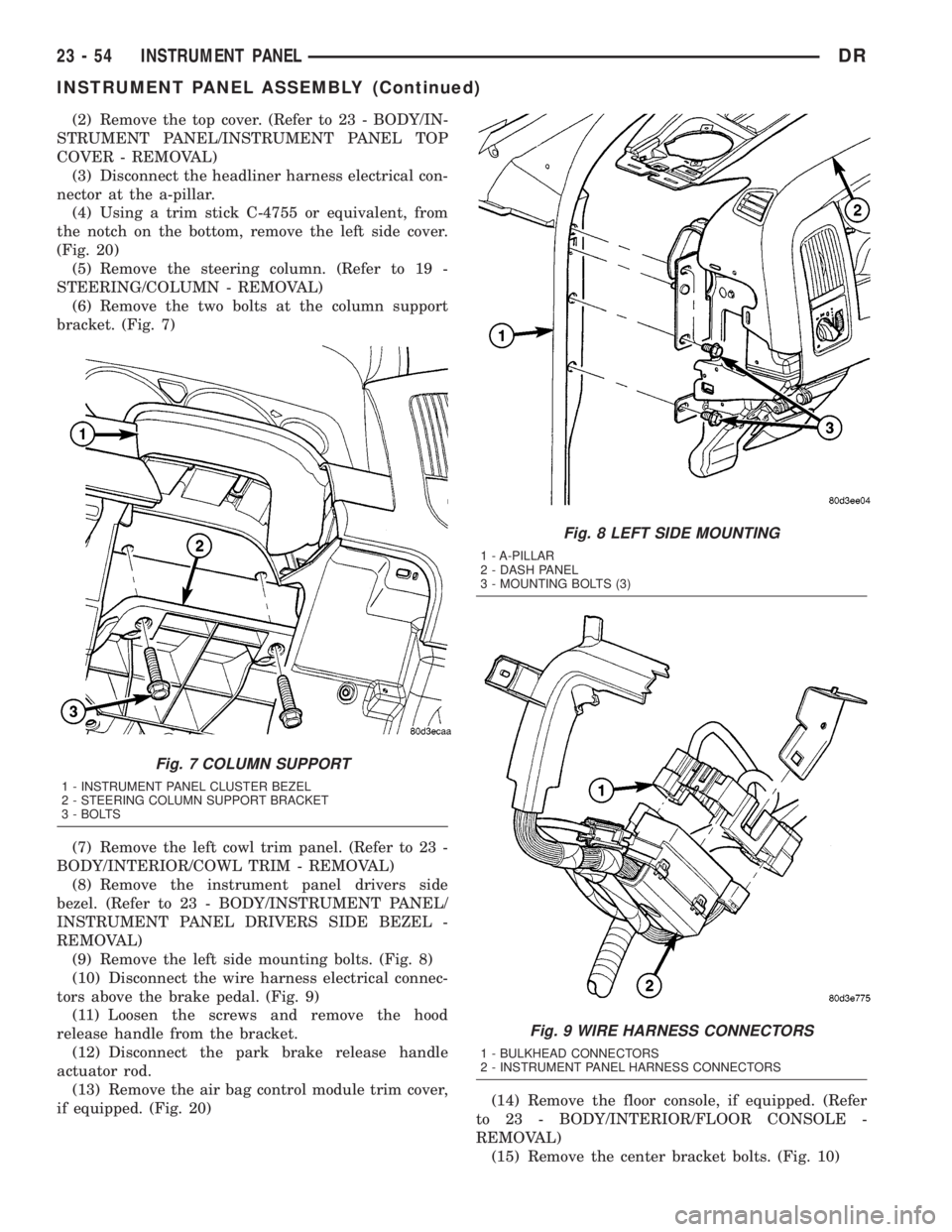
(6) Remove the two bolts at the column support
bracket. (Fig. 7)
(7) Remove the left cowl trim panel. (Refer to 23 -
BODY/INTERIOR/COWL TRIM - REMOVAL)
(8) Remove the instrument panel drivers side
bezel. (Refer to 23 - BODY/INSTRUMENT PANEL/
INSTRUMENT PANEL DRIVERS SIDE BEZEL -
REMOVAL)
(9) Remove the left side mounting bolts. (Fig. 8)
(10) Disconnect the wire harness electrical connec-
tors above the brake pedal. (Fig. 9)
(11) Loosen the screws and remove the hood
release handle from the bracket.
(12) Disconnect the park brake release handle
actuator rod.
(13) Remove the air bag control module trim cover,
if equipped. (Fig. 20)(14) Remove the floor console, if equipped. (Refer
to 23 - BODY/INTERIOR/FLOOR CONSOLE -
REMOVAL)
(15) Remove the center bracket bolts. (Fig. 10)
Fig. 7 COLUMN SUPPORT
1 - INSTRUMENT PANEL CLUSTER BEZEL
2 - STEERING COLUMN SUPPORT BRACKET
3 - BOLTS
Fig. 8 LEFT SIDE MOUNTING
1 - A-PILLAR
2 - DASH PANEL
3 - MOUNTING BOLTS (3)
Fig. 9 WIRE HARNESS CONNECTORS
1 - BULKHEAD CONNECTORS
2 - INSTRUMENT PANEL HARNESS CONNECTORS
23 - 54 INSTRUMENT PANELDR
INSTRUMENT PANEL ASSEMBLY (Continued)
Page 2631 of 2895
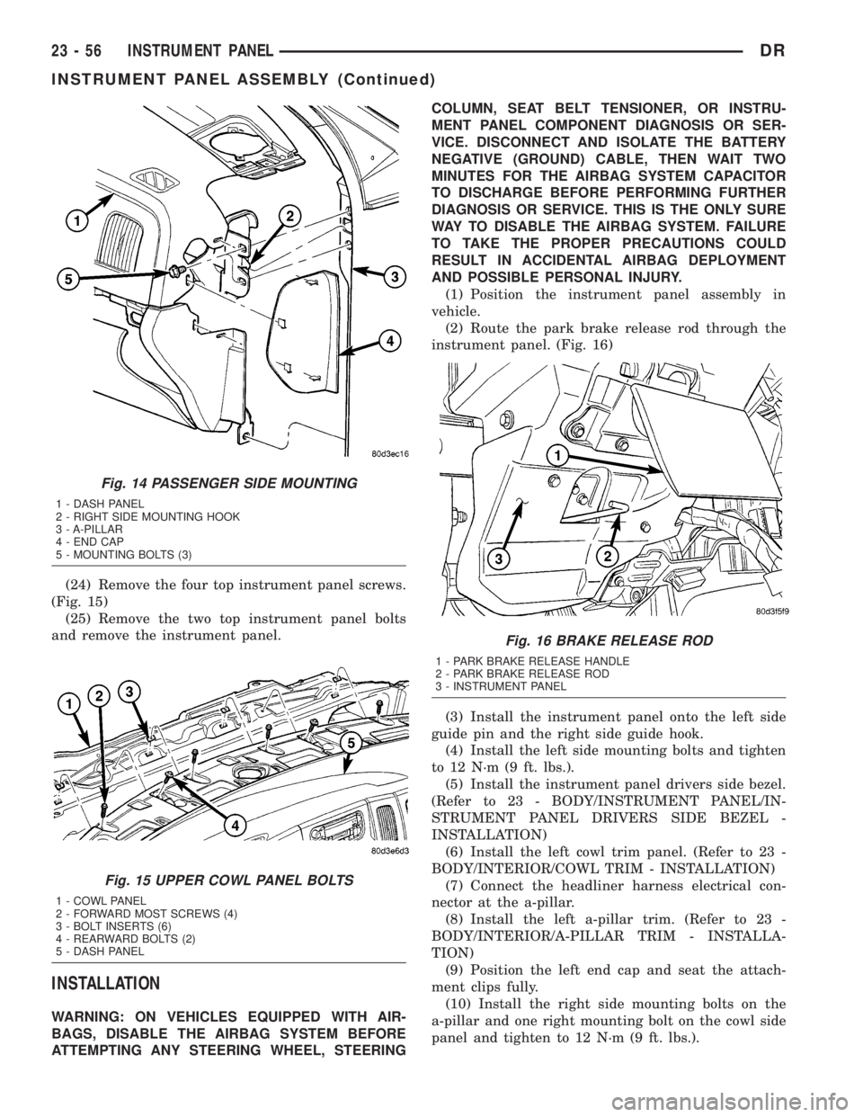
(24) Remove the four top instrument panel screws.
(Fig. 15)
(25) Remove the two top instrument panel bolts
and remove the instrument panel.
INSTALLATION
WARNING: ON VEHICLES EQUIPPED WITH AIR-
BAGS, DISABLE THE AIRBAG SYSTEM BEFORE
ATTEMPTING ANY STEERING WHEEL, STEERINGCOLUMN, SEAT BELT TENSIONER, OR INSTRU-
MENT PANEL COMPONENT DIAGNOSIS OR SER-
VICE. DISCONNECT AND ISOLATE THE BATTERY
NEGATIVE (GROUND) CABLE, THEN WAIT TWO
MINUTES FOR THE AIRBAG SYSTEM CAPACITOR
TO DISCHARGE BEFORE PERFORMING FURTHER
DIAGNOSIS OR SERVICE. THIS IS THE ONLY SURE
WAY TO DISABLE THE AIRBAG SYSTEM. FAILURE
TO TAKE THE PROPER PRECAUTIONS COULD
RESULT IN ACCIDENTAL AIRBAG DEPLOYMENT
AND POSSIBLE PERSONAL INJURY.
(1) Position the instrument panel assembly in
vehicle.
(2) Route the park brake release rod through the
instrument panel. (Fig. 16)
(3) Install the instrument panel onto the left side
guide pin and the right side guide hook.
(4) Install the left side mounting bolts and tighten
to 12 N´m (9 ft. lbs.).
(5) Install the instrument panel drivers side bezel.
(Refer to 23 - BODY/INSTRUMENT PANEL/IN-
STRUMENT PANEL DRIVERS SIDE BEZEL -
INSTALLATION)
(6) Install the left cowl trim panel. (Refer to 23 -
BODY/INTERIOR/COWL TRIM - INSTALLATION)
(7) Connect the headliner harness electrical con-
nector at the a-pillar.
(8) Install the left a-pillar trim. (Refer to 23 -
BODY/INTERIOR/A-PILLAR TRIM - INSTALLA-
TION)
(9) Position the left end cap and seat the attach-
ment clips fully.
(10) Install the right side mounting bolts on the
a-pillar and one right mounting bolt on the cowl side
panel and tighten to 12 N´m (9 ft. lbs.).
Fig. 14 PASSENGER SIDE MOUNTING
1 - DASH PANEL
2 - RIGHT SIDE MOUNTING HOOK
3 - A-PILLAR
4 - END CAP
5 - MOUNTING BOLTS (3)
Fig. 15 UPPER COWL PANEL BOLTS
1 - COWL PANEL
2 - FORWARD MOST SCREWS (4)
3 - BOLT INSERTS (6)
4 - REARWARD BOLTS (2)
5 - DASH PANEL
Fig. 16 BRAKE RELEASE ROD
1 - PARK BRAKE RELEASE HANDLE
2 - PARK BRAKE RELEASE ROD
3 - INSTRUMENT PANEL
23 - 56 INSTRUMENT PANELDR
INSTRUMENT PANEL ASSEMBLY (Continued)