2003 DODGE RAM steering
[x] Cancel search: steeringPage 1837 of 2895
REMOVAL - PRESSURE HOSE
(1) Drain and siphon the power steering system.
(2) Raise and support the vehicle.
(3) Disconnect the pressure hose at the pump.
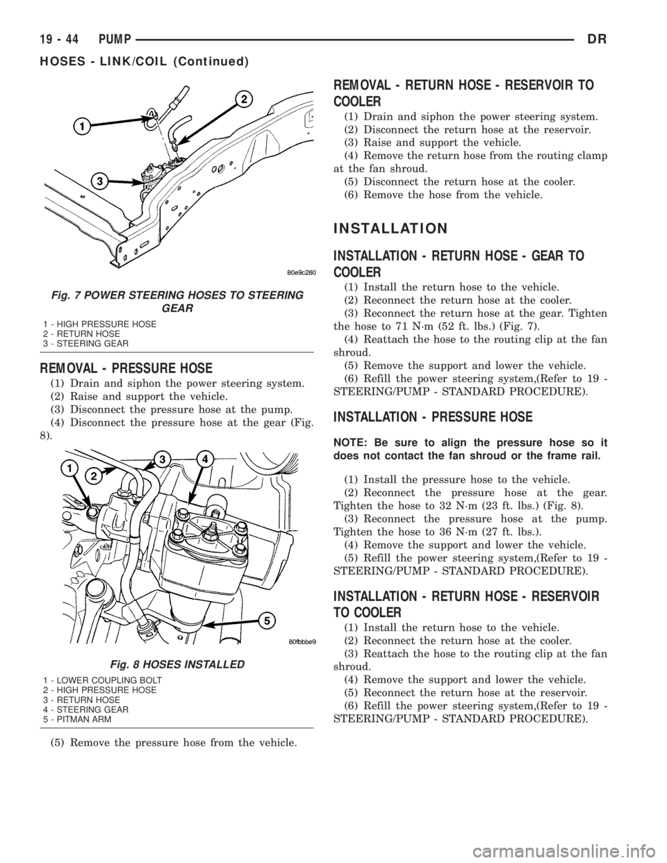
(4) Disconnect the pressure hose at the gear (Fig.
8).
(5) Remove the pressure hose from the vehicle.
REMOVAL - RETURN HOSE - RESERVOIR TO
COOLER
(1) Drain and siphon the power steering system.
(2) Disconnect the return hose at the reservoir.
(3) Raise and support the vehicle.
(4) Remove the return hose from the routing clamp
at the fan shroud.
(5) Disconnect the return hose at the cooler.
(6) Remove the hose from the vehicle.
INSTALLATION
INSTALLATION - RETURN HOSE - GEAR TO
COOLER
(1) Install the return hose to the vehicle.
(2) Reconnect the return hose at the cooler.
(3) Reconnect the return hose at the gear. Tighten
the hose to 71 N´m (52 ft. lbs.) (Fig. 7).
(4) Reattach the hose to the routing clip at the fan
shroud.
(5) Remove the support and lower the vehicle.
(6) Refill the power steering system,(Refer to 19 -
STEERING/PUMP - STANDARD PROCEDURE).
INSTALLATION - PRESSURE HOSE
NOTE: Be sure to align the pressure hose so it
does not contact the fan shroud or the frame rail.
(1) Install the pressure hose to the vehicle.
(2) Reconnect the pressure hose at the gear.
Tighten the hose to 32 N´m (23 ft. lbs.) (Fig. 8).
(3) Reconnect the pressure hose at the pump.
Tighten the hose to 36 N´m (27 ft. lbs.).
(4) Remove the support and lower the vehicle.
(5) Refill the power steering system,(Refer to 19 -
STEERING/PUMP - STANDARD PROCEDURE).
INSTALLATION - RETURN HOSE - RESERVOIR
TO COOLER
(1) Install the return hose to the vehicle.
(2) Reconnect the return hose at the cooler.
(3) Reattach the hose to the routing clip at the fan
shroud.
(4) Remove the support and lower the vehicle.
(5) Reconnect the return hose at the reservoir.
(6) Refill the power steering system,(Refer to 19 -
STEERING/PUMP - STANDARD PROCEDURE).
Fig. 7 POWER STEERING HOSES TO STEERING
GEAR
1 - HIGH PRESSURE HOSE
2 - RETURN HOSE
3 - STEERING GEAR
Fig. 8 HOSES INSTALLED
1 - LOWER COUPLING BOLT
2 - HIGH PRESSURE HOSE
3 - RETURN HOSE
4 - STEERING GEAR
5 - PITMAN ARM
19 - 44 PUMPDR
HOSES - LINK/COIL (Continued)
Page 1838 of 2895
POWER STEERING PRESSURE
SWITCH
DESCRIPTION
A pressure sensing switch is used in the power
steering system. It is mounted on the high-pressure
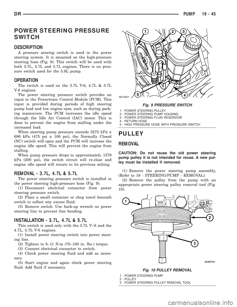
steering hose (Fig. 9). This switch will be used with
both 3.7L, 4.7L and 5.7L engines. There is no pres-
sure switch used for the 5.9L pump.
OPERATION
The switch is used on the 3.7L V-6, 4.7L & 5.7L
V-8 engines.
The power steering pressure switch provides an
input to the Powertrain Control Module (PCM). This
input is provided during periods of high steering
pump load and low engine rpm; such as during park-
ing maneuvers. The PCM increases the idle speed
through the Idle Air Control (IAC) motor. This is
done to prevent the engine from stalling under the
increased load.
When steering pump pressure exceeds 3275 kPa
690 kPa (475 psi 100 psi), the Normally Closed
(NC) switch will open and the PCM will increase the
engine idle speed. This will prevent the engine from
stalling.
When pump pressure drops to approximately 1379
kPa (200 psi), the switch circuit will re-close and
engine idle speed will return to its previous setting.
REMOVAL - 3.7L, 4.7L & 5.7L
The power steering pressure switch is installed in
the power steering high-pressure hose (Fig. 9).
(1) Disconnect electrical connector from power
steering pressure switch.
(2) Place a small container or shop towel beneath
switch to collect any excess fluid.
(3) Remove switch. Use back-up wrench on power
steering line to prevent line bending.
INSTALLATION - 3.7L, 4.7L & 5.7L
This switch is used only with the 3.7L V±6 and the
4.7L, 5.7L V-8 engines.
(1) Install power steering switch into power steer-
ing line.
(2) Tighten to 8±11 N´m (70±100 in. lbs.) torque.
(3) Connect electrical connector to switch.
(4) Check power steering fluid and add as neces-
sary.
(5) Start engine and again check power steering
fluid. Add fluid if necessary.
PULLEY
REMOVAL
CAUTION: Do not reuse the old power steering
pump pulley it is not intended for reuse. A new pul-
ley must be installed if removed.
(1) Remove the power steering pump assembly,
(Refer to 19 - STEERING/PUMP - REMOVAL).
(2) Remove the pulley from the pump with an
appropriate power steering pulley removal tool (Fig.
10).
Fig. 9 PRESSURE SWITCH
1 - POWER STEERING PULLEY
2 - POWER STEERING PUMP HOUSING
3 - POWER STEERING FLUID RESERVOIR
4 - RETURN HOSE
5 - HIGH PRESSURE HOSE WITH PRESSURE SWITCH
Fig. 10 PULLEY REMOVAL
1 - POWER STEERING PUMP
2 - PULLEY
3 - POWER STEERING PULLEY REMOVAL TOOL
DRPUMP 19 - 45
Page 1839 of 2895
INSTALLATION
CAUTION: Do not reuse the old power steering
pump pulley it is not intended for reuse. A new pul-
ley must be installed if removed.
(1) Replace the pulley if it's bent, cracked, or loose.
(2) Install the pulley on the pump with an appro-
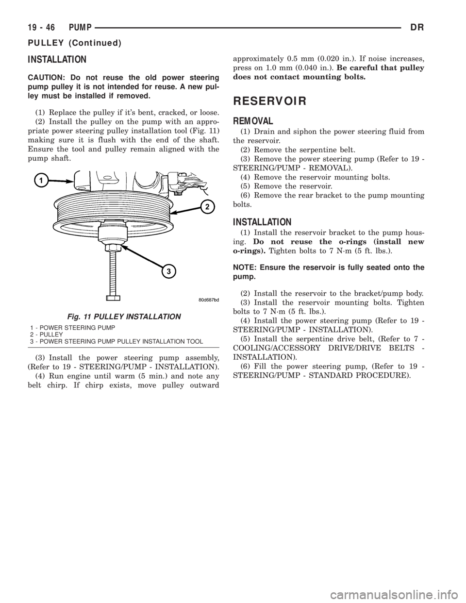
priate power steering pulley installation tool (Fig. 11)
making sure it is flush with the end of the shaft.
Ensure the tool and pulley remain aligned with the
pump shaft.
(3) Install the power steering pump assembly,
(Refer to 19 - STEERING/PUMP - INSTALLATION).
(4) Run engine until warm (5 min.) and note any
belt chirp. If chirp exists, move pulley outwardapproximately 0.5 mm (0.020 in.). If noise increases,
press on 1.0 mm (0.040 in.).Be careful that pulley
does not contact mounting bolts.
RESERVOIR
REMOVAL
(1) Drain and siphon the power steering fluid from
the reservoir.
(2) Remove the serpentine belt.
(3) Remove the power steering pump (Refer to 19 -
STEERING/PUMP - REMOVAL).
(4) Remove the reservoir mounting bolts.
(5) Remove the reservoir.
(6) Remove the rear bracket to the pump mounting
bolts.
INSTALLATION
(1) Install the reservoir bracket to the pump hous-
ing.Do not reuse the o-rings (install new
o-rings).Tighten bolts to 7 N´m (5 ft. lbs.).
NOTE: Ensure the reservoir is fully seated onto the
pump.
(2) Install the reservoir to the bracket/pump body.
(3) Install the reservoir mounting bolts. Tighten
bolts to 7 N´m (5 ft. lbs.).
(4) Install the power steering pump (Refer to 19 -
STEERING/PUMP - INSTALLATION).
(5) Install the serpentine drive belt, (Refer to 7 -
COOLING/ACCESSORY DRIVE/DRIVE BELTS -
INSTALLATION).
(6) Fill the power steering pump, (Refer to 19 -
STEERING/PUMP - STANDARD PROCEDURE).
Fig. 11 PULLEY INSTALLATION
1 - POWER STEERING PUMP
2 - PULLEY
3 - POWER STEERING PUMP PULLEY INSTALLATION TOOL
19 - 46 PUMPDR
PULLEY (Continued)
Page 2033 of 2895
(4) Tighten adjusting screw to 8 N´m (72 in. lbs.)
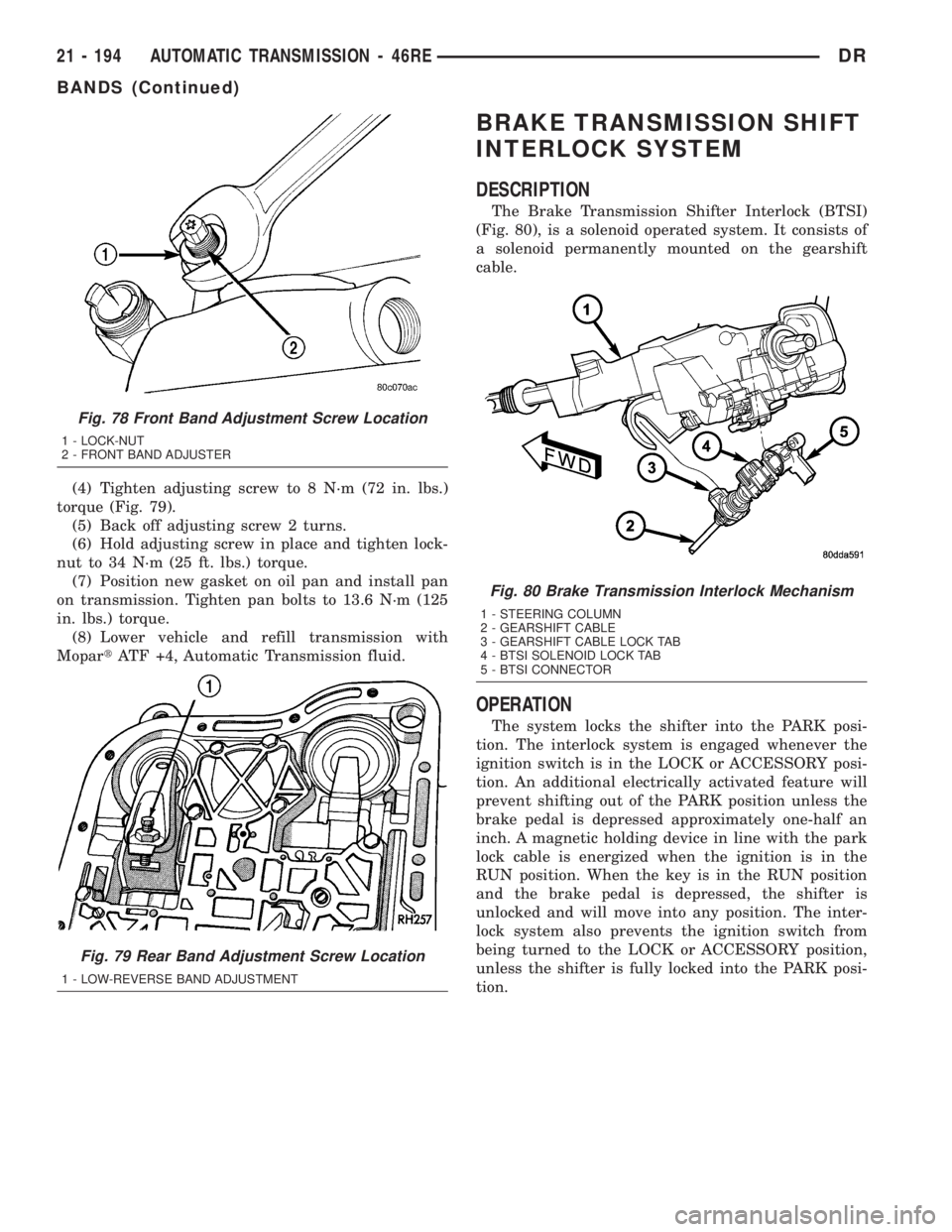
torque (Fig. 79).
(5) Back off adjusting screw 2 turns.
(6) Hold adjusting screw in place and tighten lock-
nut to 34 N´m (25 ft. lbs.) torque.
(7) Position new gasket on oil pan and install pan
on transmission. Tighten pan bolts to 13.6 N´m (125
in. lbs.) torque.
(8) Lower vehicle and refill transmission with
MopartATF +4, Automatic Transmission fluid.
BRAKE TRANSMISSION SHIFT
INTERLOCK SYSTEM
DESCRIPTION
The Brake Transmission Shifter Interlock (BTSI)
(Fig. 80), is a solenoid operated system. It consists of
a solenoid permanently mounted on the gearshift
cable.
OPERATION
The system locks the shifter into the PARK posi-
tion. The interlock system is engaged whenever the
ignition switch is in the LOCK or ACCESSORY posi-
tion. An additional electrically activated feature will
prevent shifting out of the PARK position unless the
brake pedal is depressed approximately one-half an
inch. A magnetic holding device in line with the park
lock cable is energized when the ignition is in the
RUN position. When the key is in the RUN position
and the brake pedal is depressed, the shifter is
unlocked and will move into any position. The inter-
lock system also prevents the ignition switch from
being turned to the LOCK or ACCESSORY position,
unless the shifter is fully locked into the PARK posi-
tion.
Fig. 78 Front Band Adjustment Screw Location
1 - LOCK-NUT
2 - FRONT BAND ADJUSTER
Fig. 79 Rear Band Adjustment Screw Location
1 - LOW-REVERSE BAND ADJUSTMENT
Fig. 80 Brake Transmission Interlock Mechanism
1 - STEERING COLUMN
2 - GEARSHIFT CABLE
3 - GEARSHIFT CABLE LOCK TAB
4 - BTSI SOLENOID LOCK TAB
5 - BTSI CONNECTOR
21 - 194 AUTOMATIC TRANSMISSION - 46REDR
BANDS (Continued)
Page 2034 of 2895
DIAGNOSIS AND TESTING - BRAKE
TRANSMISSION SHIFT INTERLOCK
(1) Verify that the key can only be removed in the
PARK position
(2) When the shift lever is in PARK And the shift
handle pushbutton is in the ªOUTº position, the igni-
tion key cylinder should rotate freely from OFF to
LOCK. When the shifter is in any other gear or neu-
tral position, the ignition key cylinder should not
rotate to the LOCK position.
(3) Shifting out of PARK should not be possible
when the ignition key cylinder is in the OFF posi-
tion.
(4) Shifting out of PARK should not be possible
while applying normal pushbutton force and ignition
key cylinder is in the RUN or START positions
unless the foot brake pedal is depressed approxi-
mately 1/2 inch (12mm).
(5) Shifting out of PARK should not be possible
when the ignition key cylinder is in the ACCESSORY
or LOCK positions.
(6) Shifting between any gears, NEUTRAL or into
PARK may be done without depressing foot brake
pedal with ignition switch in RUN or START posi-
tions.
ADJUSTMENTS - BRAKE TRANSMISSION
SHIFT INTERLOCK
Correct cable adjustment is important to proper
interlock operation. The gearshift cable must be cor-
rectly adjusted in order to shift out of PARK.
ADJUSTMENT PROCEDURE
(1) Remove the steering column trim as necessary
for access to the brake transmission shift interlock.
(2) Shift the transmission into the PARK position.
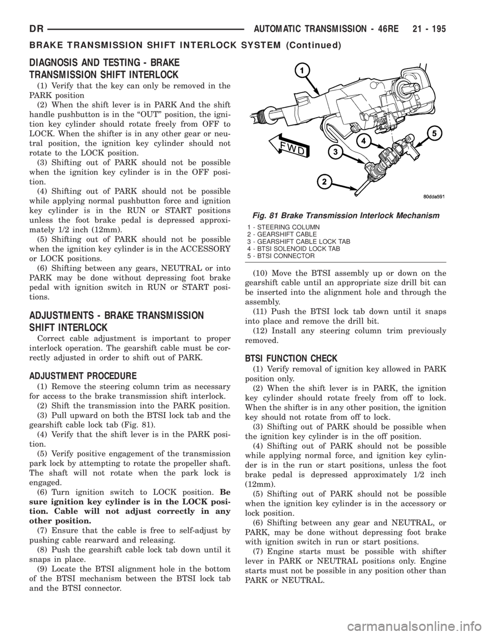
(3) Pull upward on both the BTSI lock tab and the
gearshift cable lock tab (Fig. 81).
(4) Verify that the shift lever is in the PARK posi-
tion.
(5) Verify positive engagement of the transmission
park lock by attempting to rotate the propeller shaft.
The shaft will not rotate when the park lock is
engaged.
(6) Turn ignition switch to LOCK position.Be
sure ignition key cylinder is in the LOCK posi-
tion. Cable will not adjust correctly in any
other position.
(7) Ensure that the cable is free to self-adjust by
pushing cable rearward and releasing.
(8) Push the gearshift cable lock tab down until it
snaps in place.
(9) Locate the BTSI alignment hole in the bottom
of the BTSI mechanism between the BTSI lock tab
and the BTSI connector.(10) Move the BTSI assembly up or down on the
gearshift cable until an appropriate size drill bit can
be inserted into the alignment hole and through the
assembly.
(11) Push the BTSI lock tab down until it snaps
into place and remove the drill bit.
(12) Install any steering column trim previously
removed.
BTSI FUNCTION CHECK
(1) Verify removal of ignition key allowed in PARK
position only.
(2) When the shift lever is in PARK, the ignition
key cylinder should rotate freely from off to lock.
When the shifter is in any other position, the ignition
key should not rotate from off to lock.
(3) Shifting out of PARK should be possible when
the ignition key cylinder is in the off position.
(4) Shifting out of PARK should not be possible
while applying normal force, and ignition key cylin-
der is in the run or start positions, unless the foot
brake pedal is depressed approximately 1/2 inch
(12mm).
(5) Shifting out of PARK should not be possible
when the ignition key cylinder is in the accessory or
lock position.
(6) Shifting between any gear and NEUTRAL, or
PARK, may be done without depressing foot brake
with ignition switch in run or start positions.
(7) Engine starts must be possible with shifter
lever in PARK or NEUTRAL positions only. Engine
starts must not be possible in any position other than
PARK or NEUTRAL.
Fig. 81 Brake Transmission Interlock Mechanism
1 - STEERING COLUMN
2 - GEARSHIFT CABLE
3 - GEARSHIFT CABLE LOCK TAB
4 - BTSI SOLENOID LOCK TAB
5 - BTSI CONNECTOR
DRAUTOMATIC TRANSMISSION - 46RE 21 - 195
BRAKE TRANSMISSION SHIFT INTERLOCK SYSTEM (Continued)
Page 2049 of 2895
(4) Lower the vehicle.
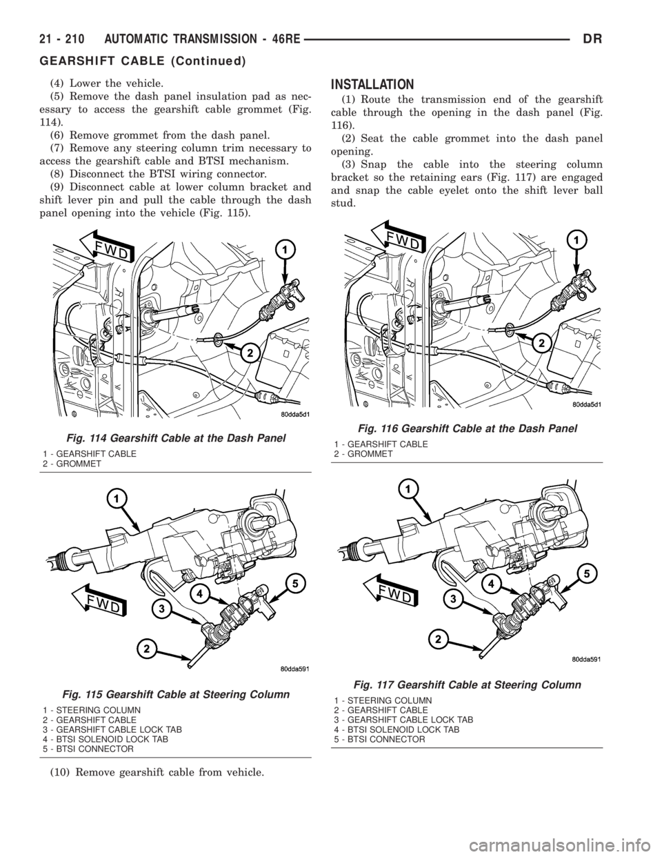
(5) Remove the dash panel insulation pad as nec-
essary to access the gearshift cable grommet (Fig.
114).
(6) Remove grommet from the dash panel.
(7) Remove any steering column trim necessary to
access the gearshift cable and BTSI mechanism.
(8) Disconnect the BTSI wiring connector.
(9) Disconnect cable at lower column bracket and
shift lever pin and pull the cable through the dash
panel opening into the vehicle (Fig. 115).
(10) Remove gearshift cable from vehicle.INSTALLATION
(1) Route the transmission end of the gearshift
cable through the opening in the dash panel (Fig.
116).
(2) Seat the cable grommet into the dash panel
opening.
(3) Snap the cable into the steering column
bracket so the retaining ears (Fig. 117) are engaged
and snap the cable eyelet onto the shift lever ball
stud.
Fig. 114 Gearshift Cable at the Dash Panel
1 - GEARSHIFT CABLE
2 - GROMMET
Fig. 115 Gearshift Cable at Steering Column
1 - STEERING COLUMN
2 - GEARSHIFT CABLE
3 - GEARSHIFT CABLE LOCK TAB
4 - BTSI SOLENOID LOCK TAB
5 - BTSI CONNECTOR
Fig. 116 Gearshift Cable at the Dash Panel
1 - GEARSHIFT CABLE
2 - GROMMET
Fig. 117 Gearshift Cable at Steering Column
1 - STEERING COLUMN
2 - GEARSHIFT CABLE
3 - GEARSHIFT CABLE LOCK TAB
4 - BTSI SOLENOID LOCK TAB
5 - BTSI CONNECTOR
21 - 210 AUTOMATIC TRANSMISSION - 46REDR
GEARSHIFT CABLE (Continued)
Page 2050 of 2895
(4) Raise the vehicle.
(5) Place the transmission manual shift lever in
the ªPARKº detent (rearmost) position and rotate
prop shaft to ensure transmission is in PARK.
(6) Route the gearshift cable through the transmis-
sion mounting bracket and secure the cable by snap-
ping the cable retaining ears into the transmission
bracket and snapping the cable eyelet on the manual
shift lever ball stud.
(7) Lower vehicle.
(8) Lock the shift cable adjustment by pressing the
cable adjuster lock tab downward until it snaps into
place.
(9) Check for proper operation of the transmission
range sensor.
(10) Adjust the gearshift cable and BTSI mecha-
nism as necessary.
ADJUSTMENTS
GEARSHIFT CABLE
Check adjustment by starting the engine in PARK
and NEUTRAL. Adjustment is CORRECT if the
engine starts only in these positions. Adjustment is
INCORRECT if the engine starts in one but not both
positions. If the engine starts in any position other
than PARK or NEUTRAL, or if the engine will not
start at all, the transmission range sensor may be
faulty.
Gearshift Adjustment Procedure
(1) Shift transmission into PARK.
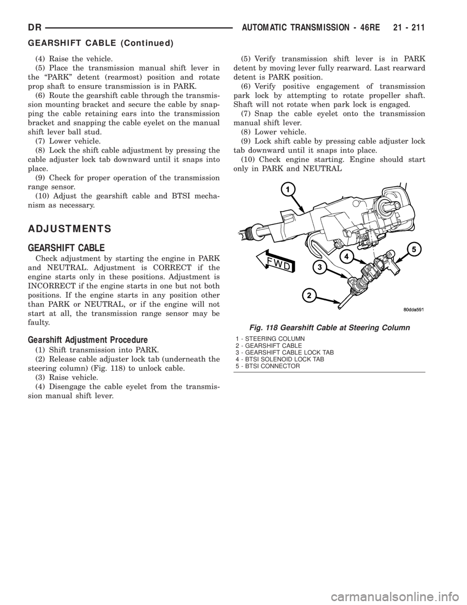
(2) Release cable adjuster lock tab (underneath the
steering column) (Fig. 118) to unlock cable.
(3) Raise vehicle.
(4) Disengage the cable eyelet from the transmis-
sion manual shift lever.(5) Verify transmission shift lever is in PARK
detent by moving lever fully rearward. Last rearward
detent is PARK position.
(6) Verify positive engagement of transmission
park lock by attempting to rotate propeller shaft.
Shaft will not rotate when park lock is engaged.
(7) Snap the cable eyelet onto the transmission
manual shift lever.
(8) Lower vehicle.
(9) Lock shift cable by pressing cable adjuster lock
tab downward until it snaps into place.
(10) Check engine starting. Engine should start
only in PARK and NEUTRAL
Fig. 118 Gearshift Cable at Steering Column
1 - STEERING COLUMN
2 - GEARSHIFT CABLE
3 - GEARSHIFT CABLE LOCK TAB
4 - BTSI SOLENOID LOCK TAB
5 - BTSI CONNECTOR
DRAUTOMATIC TRANSMISSION - 46RE 21 - 211
GEARSHIFT CABLE (Continued)
Page 2214 of 2895
REAR BAND
The transmission oil pan must be removed for
access to the rear band adjusting screw.
(1) Raise vehicle.
(2) Remove transmission oil pan and drain fluid.
(3) Loosen band adjusting screw locknut 5-6 turns.
Be sure adjusting screw turns freely in lever.
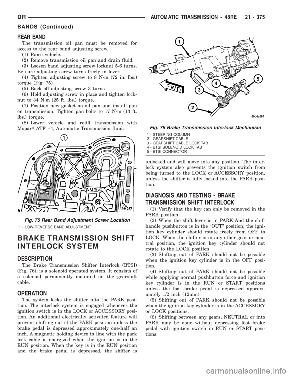
(4) Tighten adjusting screw to 8 N´m (72 in. lbs.)
torque (Fig. 75).
(5) Back off adjusting screw 3 turns.
(6) Hold adjusting screw in place and tighten lock-
nut to 34 N´m (25 ft. lbs.) torque.
(7) Position new gasket on oil pan and install pan
on transmission. Tighten pan bolts to 17 N´m (13 ft.
lbs.) torque.
(8) Lower vehicle and refill transmission with
MopartATF +4, Automatic Transmission fluid.
BRAKE TRANSMISSION SHIFT
INTERLOCK SYSTEM
DESCRIPTION
The Brake Transmission Shifter Interlock (BTSI)
(Fig. 76), is a solenoid operated system. It consists of
a solenoid permanently mounted on the gearshift
cable.
OPERATION
The system locks the shifter into the PARK posi-
tion. The interlock system is engaged whenever the
ignition switch is in the LOCK or ACCESSORY posi-
tion. An additional electrically activated feature will
prevent shifting out of the PARK position unless the
brake pedal is depressed approximately one-half an
inch. A magnetic holding device in line with the park
lock cable is energized when the ignition is in the
RUN position. When the key is in the RUN position
and the brake pedal is depressed, the shifter isunlocked and will move into any position. The inter-
lock system also prevents the ignition switch from
being turned to the LOCK or ACCESSORY position,
unless the shifter is fully locked into the PARK posi-
tion.
DIAGNOSIS AND TESTING - BRAKE
TRANSMISSION SHIFT INTERLOCK
(1) Verify that the key can only be removed in the
PARK position
(2) When the shift lever is in PARK And the shift
handle pushbutton is in the ªOUTº position, the igni-
tion key cylinder should rotate freely from OFF to
LOCK. When the shifter is in any other gear or neu-
tral position, the ignition key cylinder should not
rotate to the LOCK position.
(3) Shifting out of PARK should not be possible
when the ignition key cylinder is in the OFF posi-
tion.
(4) Shifting out of PARK should not be possible
while applying normal pushbutton force and ignition
key cylinder is in the RUN or START positions
unless the foot brake pedal is depressed approxi-
mately 1/2 inch (12mm).
(5) Shifting out of PARK should not be possible
when the ignition key cylinder is in the ACCESSORY
or LOCK positions.
(6) Shifting between any gears, NEUTRAL or into
PARK may be done without depressing foot brake
pedal with ignition switch in RUN or START posi-
tions.
Fig. 75 Rear Band Adjustment Screw Location
1 - LOW-REVERSE BAND ADJUSTMENT
Fig. 76 Brake Transmission Interlock Mechanism
1 - STEERING COLUMN
2 - GEARSHIFT CABLE
3 - GEARSHIFT CABLE LOCK TAB
4 - BTSI SOLENOID LOCK TAB
5 - BTSI CONNECTOR
DRAUTOMATIC TRANSMISSION - 48RE 21 - 375
BANDS (Continued)