2003 DODGE RAM steering
[x] Cancel search: steeringPage 1805 of 2895
KEY CYLINDER
REMOVAL
The ignition key must be in the key cylinder for
cylinder removal.
(1) Disconnect negative cable from battery.
(2) Remove upper and lower covers (shrouds) from
steering column.
(3) Place shifter in PARK position.
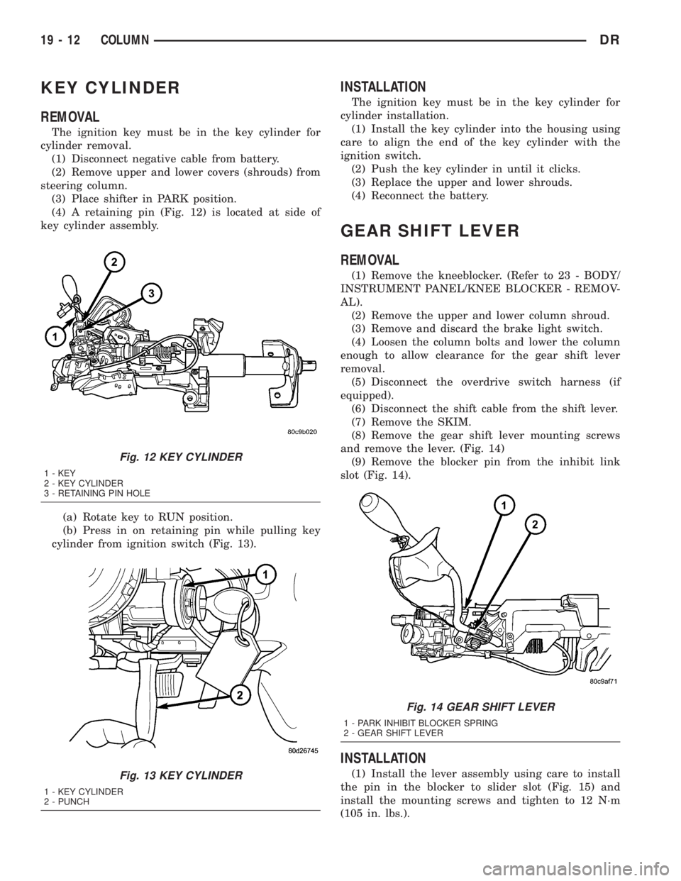
(4) A retaining pin (Fig. 12) is located at side of
key cylinder assembly.
(a) Rotate key to RUN position.
(b) Press in on retaining pin while pulling key
cylinder from ignition switch (Fig. 13).
INSTALLATION
The ignition key must be in the key cylinder for
cylinder installation.
(1) Install the key cylinder into the housing using
care to align the end of the key cylinder with the
ignition switch.
(2) Push the key cylinder in until it clicks.
(3) Replace the upper and lower shrouds.
(4) Reconnect the battery.
GEAR SHIFT LEVER
REMOVAL
(1) Remove the kneeblocker. (Refer to 23 - BODY/
INSTRUMENT PANEL/KNEE BLOCKER - REMOV-
AL).
(2) Remove the upper and lower column shroud.
(3) Remove and discard the brake light switch.
(4) Loosen the column bolts and lower the column
enough to allow clearance for the gear shift lever
removal.
(5) Disconnect the overdrive switch harness (if
equipped).
(6) Disconnect the shift cable from the shift lever.
(7) Remove the SKIM.
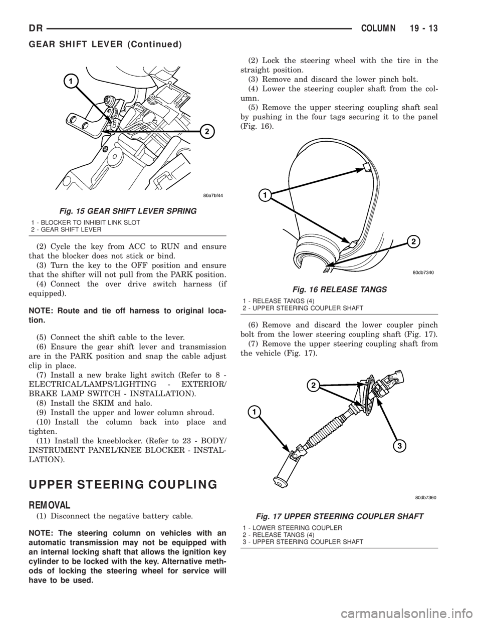
(8) Remove the gear shift lever mounting screws
and remove the lever. (Fig. 14)
(9) Remove the blocker pin from the inhibit link
slot (Fig. 14).
INSTALLATION
(1) Install the lever assembly using care to install
the pin in the blocker to slider slot (Fig. 15) and
install the mounting screws and tighten to 12 N´m
(105 in. lbs.).
Fig. 12 KEY CYLINDER
1 - KEY
2 - KEY CYLINDER
3 - RETAINING PIN HOLE
Fig. 13 KEY CYLINDER
1 - KEY CYLINDER
2 - PUNCH
Fig. 14 GEAR SHIFT LEVER
1 - PARK INHIBIT BLOCKER SPRING
2 - GEAR SHIFT LEVER
19 - 12 COLUMNDR
Page 1806 of 2895
(2) Cycle the key from ACC to RUN and ensure
that the blocker does not stick or bind.
(3) Turn the key to the OFF position and ensure
that the shifter will not pull from the PARK position.
(4) Connect the over drive switch harness (if
equipped).
NOTE: Route and tie off harness to original loca-
tion.
(5) Connect the shift cable to the lever.
(6) Ensure the gear shift lever and transmission
are in the PARK position and snap the cable adjust
clip in place.
(7) Install a new brake light switch (Refer to 8 -
ELECTRICAL/LAMPS/LIGHTING - EXTERIOR/
BRAKE LAMP SWITCH - INSTALLATION).
(8) Install the SKIM and halo.
(9) Install the upper and lower column shroud.
(10) Install the column back into place and
tighten.
(11) Install the kneeblocker. (Refer to 23 - BODY/
INSTRUMENT PANEL/KNEE BLOCKER - INSTAL-
LATION).
UPPER STEERING COUPLING
REMOVAL
(1) Disconnect the negative battery cable.
NOTE: The steering column on vehicles with an
automatic transmission may not be equipped with
an internal locking shaft that allows the ignition key
cylinder to be locked with the key. Alternative meth-
ods of locking the steering wheel for service will
have to be used.(2) Lock the steering wheel with the tire in the
straight position.
(3) Remove and discard the lower pinch bolt.
(4) Lower the steering coupler shaft from the col-
umn.
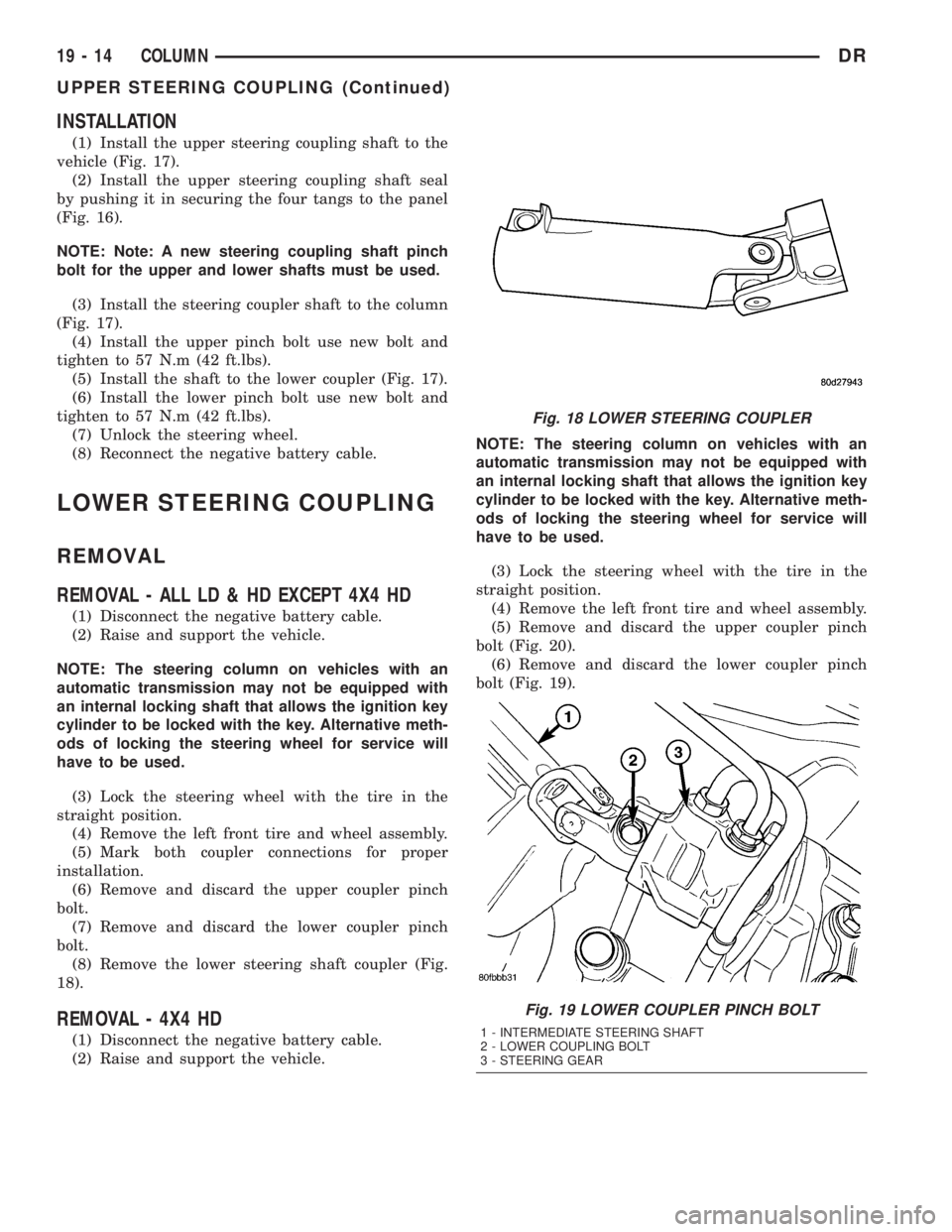
(5) Remove the upper steering coupling shaft seal
by pushing in the four tags securing it to the panel
(Fig. 16).
(6) Remove and discard the lower coupler pinch
bolt from the lower steering coupling shaft (Fig. 17).
(7) Remove the upper steering coupling shaft from
the vehicle (Fig. 17).
Fig. 15 GEAR SHIFT LEVER SPRING
1 - BLOCKER TO INHIBIT LINK SLOT
2 - GEAR SHIFT LEVER
Fig. 16 RELEASE TANGS
1 - RELEASE TANGS (4)
2 - UPPER STEERING COUPLER SHAFT
Fig. 17 UPPER STEERING COUPLER SHAFT
1 - LOWER STEERING COUPLER
2 - RELEASE TANGS (4)
3 - UPPER STEERING COUPLER SHAFT
DRCOLUMN 19 - 13
GEAR SHIFT LEVER (Continued)
Page 1807 of 2895
INSTALLATION
(1) Install the upper steering coupling shaft to the
vehicle (Fig. 17).
(2) Install the upper steering coupling shaft seal
by pushing it in securing the four tangs to the panel
(Fig. 16).
NOTE: Note: A new steering coupling shaft pinch
bolt for the upper and lower shafts must be used.
(3) Install the steering coupler shaft to the column
(Fig. 17).
(4) Install the upper pinch bolt use new bolt and
tighten to 57 N.m (42 ft.lbs).
(5) Install the shaft to the lower coupler (Fig. 17).
(6) Install the lower pinch bolt use new bolt and
tighten to 57 N.m (42 ft.lbs).
(7) Unlock the steering wheel.
(8) Reconnect the negative battery cable.
LOWER STEERING COUPLING
REMOVAL
REMOVAL - ALL LD & HD EXCEPT 4X4 HD
(1) Disconnect the negative battery cable.
(2) Raise and support the vehicle.
NOTE: The steering column on vehicles with an
automatic transmission may not be equipped with
an internal locking shaft that allows the ignition key
cylinder to be locked with the key. Alternative meth-
ods of locking the steering wheel for service will
have to be used.
(3) Lock the steering wheel with the tire in the
straight position.
(4) Remove the left front tire and wheel assembly.
(5) Mark both coupler connections for proper
installation.
(6) Remove and discard the upper coupler pinch
bolt.
(7) Remove and discard the lower coupler pinch
bolt.
(8) Remove the lower steering shaft coupler (Fig.
18).
REMOVAL - 4X4 HD
(1) Disconnect the negative battery cable.
(2) Raise and support the vehicle.NOTE: The steering column on vehicles with an
automatic transmission may not be equipped with
an internal locking shaft that allows the ignition key
cylinder to be locked with the key. Alternative meth-
ods of locking the steering wheel for service will
have to be used.
(3) Lock the steering wheel with the tire in the
straight position.
(4) Remove the left front tire and wheel assembly.
(5) Remove and discard the upper coupler pinch
bolt (Fig. 20).
(6) Remove and discard the lower coupler pinch
bolt (Fig. 19).
Fig. 18 LOWER STEERING COUPLER
Fig. 19 LOWER COUPLER PINCH BOLT
1 - INTERMEDIATE STEERING SHAFT
2 - LOWER COUPLING BOLT
3 - STEERING GEAR
19 - 14 COLUMNDR
UPPER STEERING COUPLING (Continued)
Page 1808 of 2895
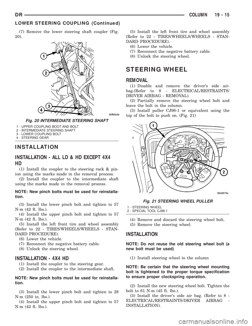
(7) Remove the lower steering shaft coupler (Fig.
20).
INSTALLATION
INSTALLATION - ALL LD & HD EXCEPT 4X4
HD
(1) Install the coupler to the steering rack & pin-
ion using the marks made in the removal process.
(2) Install the coupler to the intermediate shaft
using the marks made in the removal process.
NOTE: New pinch bolts must be used for reinstalla-
tion.
(3) Install the lower pinch bolt and tighten to 57
N´m (42 ft. lbs.).
(4) Install the upper pinch bolt and tighten to 57
N´m (42 ft. lbs.).
(5) Install the left front tire and wheel assembly
(Refer to 22 - TIRES/WHEELS/WHEELS - STAN-
DARD PROCEDURE).
(6) Lower the vehicle.
(7) Reconnect the negative battery cable.
(8) Unlock the steering wheel.
INSTALLATION - 4X4 HD
(1) Install the coupler to the steering gear.
(2) Install the coupler to the intermediate shaft.
NOTE: New pinch bolts must be used for reinstalla-
tion.
(3) Install the lower pinch bolt and tighten to 28
N´m (250 in. lbs.).
(4) Install the upper pinch bolt and tighten to 57
N´m (42 ft. lbs.).(5) Install the left front tire and wheel assembly
(Refer to 22 - TIRES/WHEELS/WHEELS - STAN-
DARD PROCEDURE).
(6) Lower the vehicle.
(7) Reconnect the negative battery cable.
(8) Unlock the steering wheel.
STEERING WHEEL
REMOVAL
(1) Disable and remove the driver's side air-
bag.(Refer to 8 - ELECTRICAL/RESTRAINTS/
DRIVER AIRBAG - REMOVAL).
(2) Partially remove the steering wheel bolt and
leave the bolt in the column.
(3) Install puller CJ98-1 or equivalent using the
top of the bolt to push on. (Fig. 21)
(4) Remove and discard the steering wheel bolt.
(5) Remove the steering wheel.
INSTALLATION
NOTE: Do not reuse the old steering wheel bolt (a
new bolt must be used)
(1) Install steering wheel to the column
NOTE: Be certain that the steering wheel mounting
bolt is tightened to the proper torque specification
to ensure proper clockspring operation.
(2) Install the new steering wheel bolt. Tighten the
bolt to 61 N´m (45 ft. lbs.).
(3) Install the driver's side air bag. (Refer to 8 -
ELECTRICAL/RESTRAINTS/DRIVER AIRBAG -
INSTALLATION).
Fig. 20 INTERMEDIATE STEERING SHAFT
1 - UPPER COUPLING BOOT AND BOLT
2 - INTERMEDIATE STEERING SHAFT
3 - LOWER COUPLING BOLT
4 - STEERING GEAR
Fig. 21 STEERING WHEEL PULLER
1 - STEERING WHEEL
2 - SPECIAL TOOL CJ98-1
DRCOLUMN 19 - 15
LOWER STEERING COUPLING (Continued)
Page 1809 of 2895
GEAR - INDEPENDENT FRONT SUSPENSION
TABLE OF CONTENTS
page page
GEAR - INDEPENDENT FRONT SUSPENSION
DESCRIPTION.........................16
REMOVAL.............................16
INSTALLATION.........................17
SPECIFICATIONS
TORQUE CHART......................18BUSHING
REMOVAL.............................18
INSTALLATION.........................18
GEAR - INDEPENDENT FRONT
SUSPENSION
DESCRIPTION
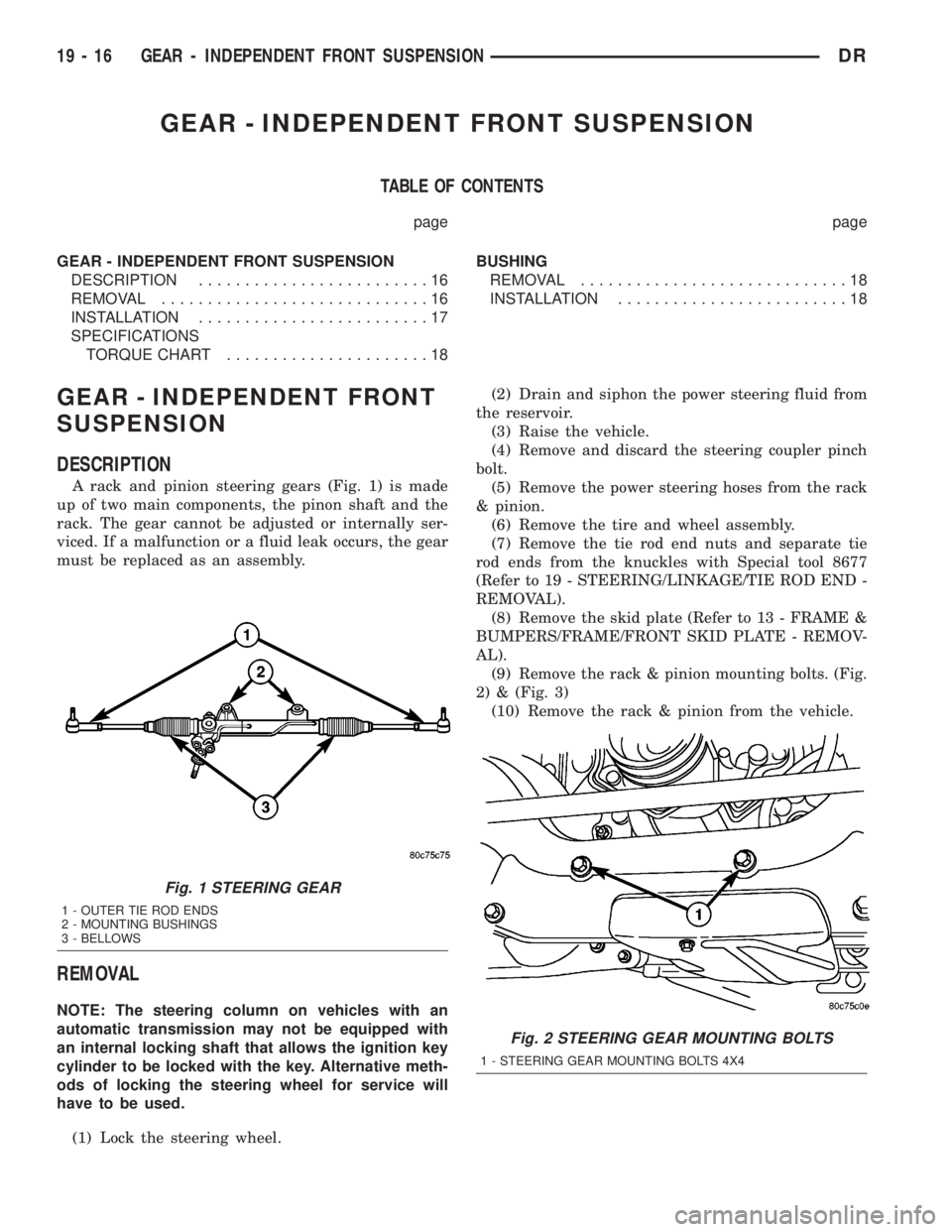
A rack and pinion steering gears (Fig. 1) is made
up of two main components, the pinon shaft and the
rack. The gear cannot be adjusted or internally ser-
viced. If a malfunction or a fluid leak occurs, the gear
must be replaced as an assembly.
REMOVAL
NOTE: The steering column on vehicles with an
automatic transmission may not be equipped with
an internal locking shaft that allows the ignition key
cylinder to be locked with the key. Alternative meth-
ods of locking the steering wheel for service will
have to be used.
(1) Lock the steering wheel.(2) Drain and siphon the power steering fluid from
the reservoir.
(3) Raise the vehicle.
(4) Remove and discard the steering coupler pinch
bolt.
(5) Remove the power steering hoses from the rack
& pinion.
(6) Remove the tire and wheel assembly.
(7) Remove the tie rod end nuts and separate tie
rod ends from the knuckles with Special tool 8677
(Refer to 19 - STEERING/LINKAGE/TIE ROD END -
REMOVAL).
(8) Remove the skid plate (Refer to 13 - FRAME &
BUMPERS/FRAME/FRONT SKID PLATE - REMOV-
AL).
(9) Remove the rack & pinion mounting bolts. (Fig.
2) & (Fig. 3)
(10) Remove the rack & pinion from the vehicle.
Fig. 1 STEERING GEAR
1 - OUTER TIE ROD ENDS
2 - MOUNTING BUSHINGS
3 - BELLOWS
Fig. 2 STEERING GEAR MOUNTING BOLTS
1 - STEERING GEAR MOUNTING BOLTS 4X4
19 - 16 GEAR - INDEPENDENT FRONT SUSPENSIONDR
Page 1810 of 2895
INSTALLATION
NOTE: Before installing gear inspect bushings and
replace if worn or damaged.
NOTE: In the frame there is two holes for the
mounting of the steering gear one is slotted and
one is round, When tightening the gear to specifi-
cations make sure to tighten the mounting bolt with
the hole first to avoided movement of the steering
gear.
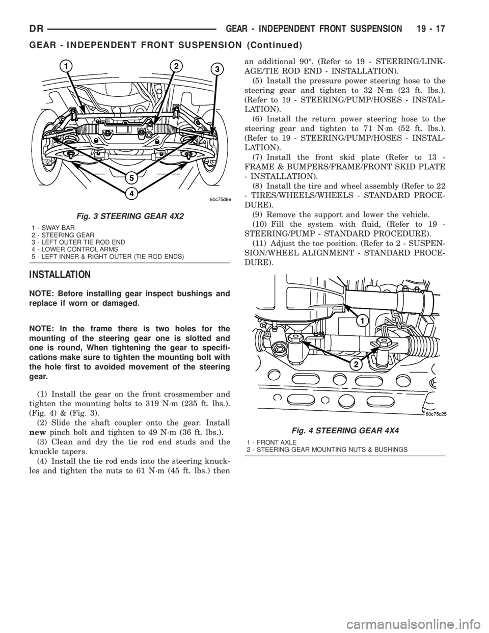
(1) Install the gear on the front crossmember and
tighten the mounting bolts to 319 N´m (235 ft. lbs.).
(Fig. 4) & (Fig. 3).
(2) Slide the shaft coupler onto the gear. Install
newpinch bolt and tighten to 49 N´m (36 ft. lbs.).
(3) Clean and dry the tie rod end studs and the
knuckle tapers.
(4) Install the tie rod ends into the steering knuck-
les and tighten the nuts to 61 N´m (45 ft. lbs.) thenan additional 90É. (Refer to 19 - STEERING/LINK-
AGE/TIE ROD END - INSTALLATION).
(5) Install the pressure power steering hose to the
steering gear and tighten to 32 N´m (23 ft. lbs.).
(Refer to 19 - STEERING/PUMP/HOSES - INSTAL-
LATION).
(6) Install the return power steering hose to the
steering gear and tighten to 71 N´m (52 ft. lbs.).
(Refer to 19 - STEERING/PUMP/HOSES - INSTAL-
LATION).
(7) Install the front skid plate (Refer to 13 -
FRAME & BUMPERS/FRAME/FRONT SKID PLATE
- INSTALLATION).
(8) Install the tire and wheel assembly (Refer to 22
- TIRES/WHEELS/WHEELS - STANDARD PROCE-
DURE).
(9) Remove the support and lower the vehicle.
(10) Fill the system with fluid, (Refer to 19 -
STEERING/PUMP - STANDARD PROCEDURE).
(11) Adjust the toe position. (Refer to 2 - SUSPEN-
SION/WHEEL ALIGNMENT - STANDARD PROCE-
DURE).
Fig. 3 STEERING GEAR 4X2
1-SWAYBAR
2 - STEERING GEAR
3 - LEFT OUTER TIE ROD END
4 - LOWER CONTROL ARMS
5 - LEFT INNER & RIGHT OUTER (TIE ROD ENDS)
Fig. 4 STEERING GEAR 4X4
1 - FRONT AXLE
2 - STEERING GEAR MOUNTING NUTS & BUSHINGS
DRGEAR - INDEPENDENT FRONT SUSPENSION 19 - 17
GEAR - INDEPENDENT FRONT SUSPENSION (Continued)
Page 1811 of 2895
SPECIFICATIONS
TORQUE CHART
TORQUE SPECIFICATIONS
DESCRIPTION N´m Ft. Lbs. In. Lbs.
Rack and Pinion Steering
Gear
Gear to Frame Bolts319 235 Ð
Rack and Pinion Steering
Gear
Coupler Bolt49 36 Ð
Tie Rod End
Knuckle Nut61
Then tighten an additional
90É45
Then tighten an additional
90ÉÐ
Tie Rod End
Jam Nut75 55 Ð
Power Steering Line
Pressure Line32 23 Ð
Power Steering Line
Return Line71 52 Ð
Power Steering Line
Pressure Line To Pump37 27 Ð
BUSHING
REMOVAL
(1) Remove the steering gear (Refer to 19 -
STEERING/GEAR - REMOVAL).
CAUTION: Do not overtighten the vise on the gear
case.
(2) Mount the steering gear in a soft jawed vise.
NOTE: If the bushings are seized a brass punch can
be used to remove the bushings from the gear
using care not to strike the gear.
(3) Remove the front mounting bushings.
(4) Remove the rear mounting bushings.
(5) Remove the steering gear from the vise and
place it on the bench.
INSTALLATION
NOTE: Coat all bushings with a thin rubber lubri-
cate oil prior to installation.
NOTE: A rubber mallet can be used to assist in the
installation of the bushings once lubricated.
(1) Coat the rear bushings with a thin rubber
lubricate oil then install the rear bushings using a
rubber mallet to seat the bushings in the gear.
(2) Coat the front bushings with a thin rubber
lubricate oil then install the front bushings using a
rubber mallet to seat the bushings in the gear.
(3) Install the steering gear (Refer to 19 - STEER-
ING/GEAR - INSTALLATION).
(4) Adjust the toe position (if necessary) (Refer to 2
- SUSPENSION/WHEEL ALIGNMENT - STAN-
DARD PROCEDURE).
19 - 18 GEAR - INDEPENDENT FRONT SUSPENSIONDR
GEAR - INDEPENDENT FRONT SUSPENSION (Continued)
Page 1812 of 2895
GEAR - LINK/COIL
TABLE OF CONTENTS
page page
GEAR - LINK/COIL
DESCRIPTION.........................19
OPERATION...........................19
REMOVAL.............................19
INSTALLATION.........................20
ADJUSTMENTS
ADJUSTMENT........................20
SPECIFICATIONS
POWER STEERING GEAR..............21
TORQUE CHART......................22
SPECIAL TOOLS
POWER STEERING GEAR..............22
PITMAN SHAFT SEAL
REMOVAL
REMOVAL - GAS ENGINE...............23REMOVAL - DIESEL...................24
INSTALLATION
INSTALLATION - GAS ENGINE...........24
INSTALLATION - DIESEL................25
STEERING GEAR INPUT SHAFT SEAL
REMOVAL.............................25
INSTALLATION.........................28
PITMAN SHAFT
REMOVAL
REMOVAL - GAS......................29
REMOVAL - DIESEL...................30
INSTALLATION
INSTALLATION - GAS..................30
INSTALLATION - DIESEL................30
GEAR - LINK/COIL
DESCRIPTION
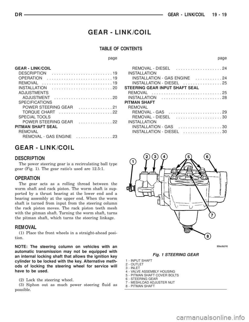
The power steering gear is a recirculating ball type
gear (Fig. 1). The gear ratio's used are 12.5:1.
OPERATION
The gear acts as a rolling thread between the
worm shaft and rack piston. The worm shaft is sup-
ported by a thrust bearing at the lower end and a
bearing assembly at the upper end. When the worm
shaft is turned from input from the steering column
the rack piston moves. The rack piston teeth mesh
with the pitman shaft. Turning the worm shaft, turns
the pitman shaft, which turns the steering linkage.
REMOVAL
(1) Place the front wheels in a straight-ahead posi-
tion.
NOTE: The steering column on vehicles with an
automatic transmission may not be equipped with
an internal locking shaft that allows the ignition key
cylinder to be locked with the key. Alternative meth-
ods of locking the steering wheel for service will
have to be used.
(2) Lock the steering wheel.
(3) Siphon out as much power steering fluid as
possible.
Fig. 1 STEERING GEAR
1 - INPUT SHAFT
2 - OUTLET
3 - INLET
4 - VALVE ASSEMBLY HOUSING
5 - PITMAN SHAFT COVER BOLTS
6 - STEERING GEAR
7 - MESHLOAD ADJUSTER NUT
8 - PITMAN SHAFT
DRGEAR - LINK/COIL 19 - 19