2003 DODGE RAM transmission
[x] Cancel search: transmissionPage 1576 of 2895
(11) Install the flywheel housing and bolts. Torque
bolts to 77 N´m (57 ft. lbs.).
(12) Install the flywheel or converter drive plate.
Tighten bolts to 137 N´m (101 ft. lbs.).
(13) Install the starter motor and torque to 43 N´m
(21 ft. lbs.)(Refer to 8 - ELECTRICAL/STARTING/
STARTER MOTOR - INSTALLATION).
(14) Install the transmission and transfer case (if
equipped).
(15) Lower vehicle.
(16) Fill the crankcase with new engine oil.
(17) Connect the battery negative cables.
(18) Start engine and check for oil leaks.
SOLID LIFTERS/TAPPETS
REMOVAL
NOTE: This procedure requires use of Miller Tool
8502 Tappet Replacement Kit.
(1) Remove camshaft (Refer to 9 - ENGINE/EN-
GINE BLOCK/CAMSHAFT & BEARINGS (IN
BLOCK) - REMOVAL).
(2) Insert the trough (provided with tool kit) the
full length of the camshaft bore (Fig. 79). Make sure
the cap end goes in first and the open side faces up
(towards tappets).
(3)Remove only one tappet at a time.Remove
rubber band from one cylinder pair and attach tappet
dowel not being removed to the next cylinder pair
(Fig. 80).
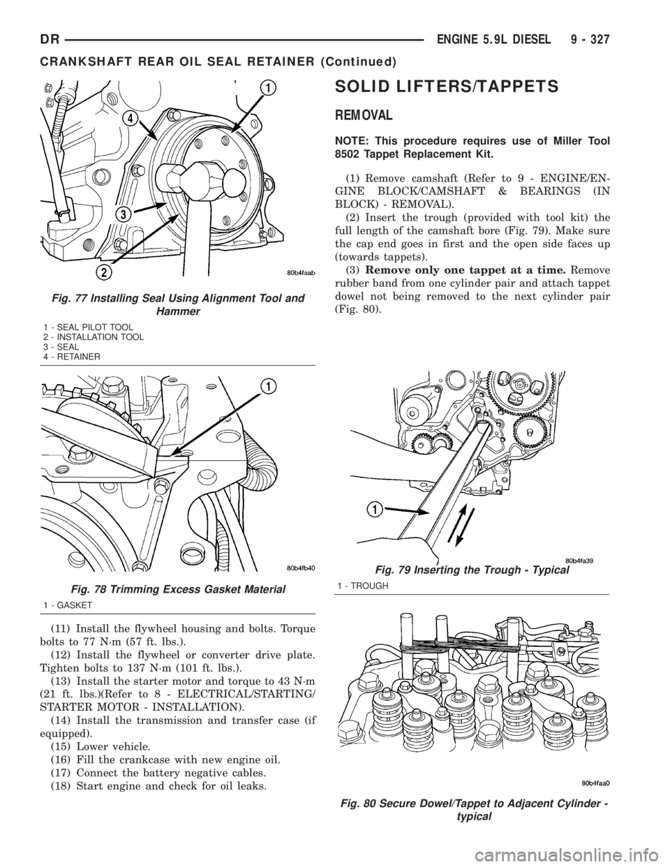
Fig. 79 Inserting the Trough - Typical
1 - TROUGH
Fig. 80 Secure Dowel/Tappet to Adjacent Cylinder -
typical
Fig. 77 Installing Seal Using Alignment Tool and
Hammer
1 - SEAL PILOT TOOL
2 - INSTALLATION TOOL
3 - SEAL
4 - RETAINER
Fig. 78 Trimming Excess Gasket Material
1 - GASKET
DRENGINE 5.9L DIESEL 9 - 327
CRANKSHAFT REAR OIL SEAL RETAINER (Continued)
Page 1586 of 2895
REAR MOUNT
REMOVAL
(1) Raise the vehicle on a hoist.
(2) Position a transmission jack in place.
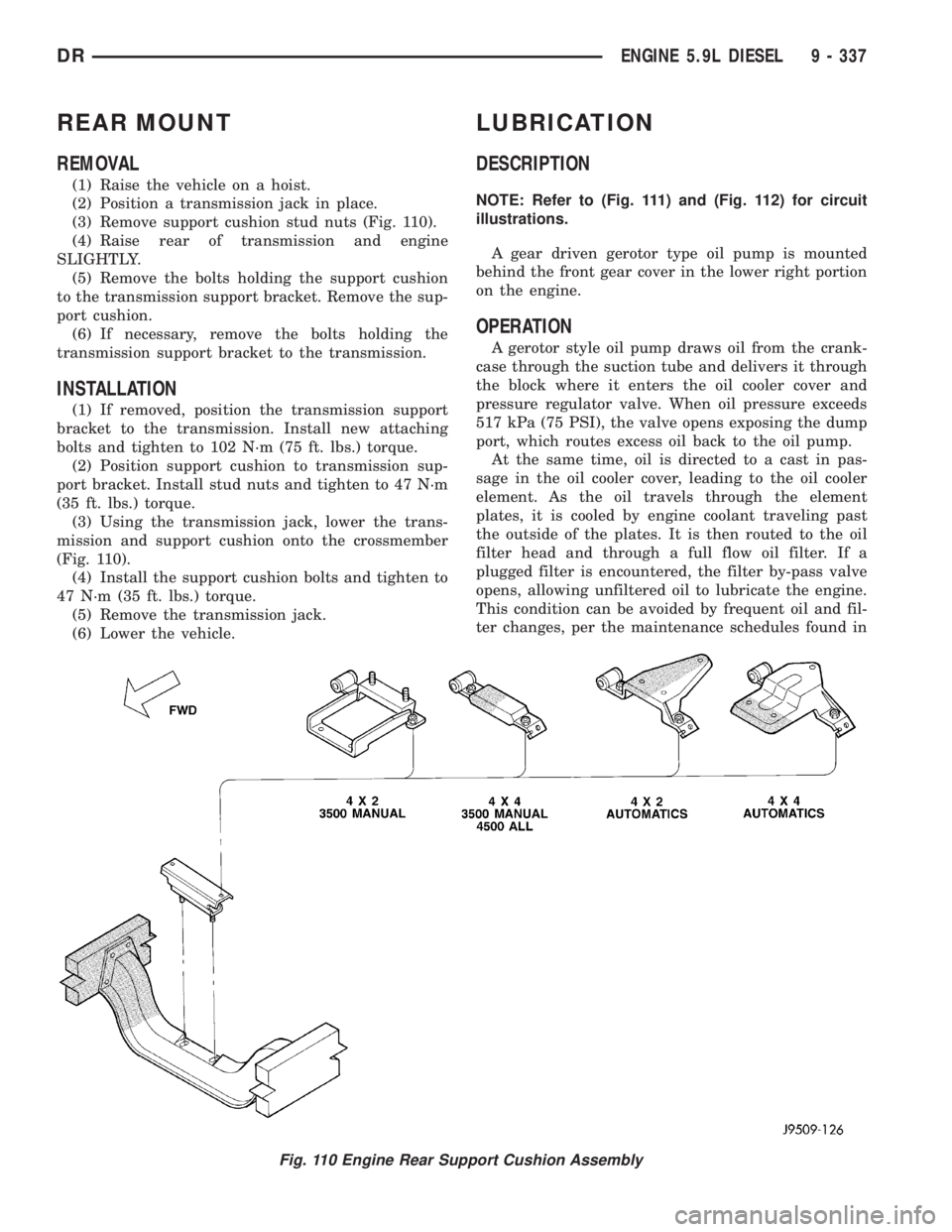
(3) Remove support cushion stud nuts (Fig. 110).
(4) Raise rear of transmission and engine
SLIGHTLY.
(5) Remove the bolts holding the support cushion
to the transmission support bracket. Remove the sup-
port cushion.
(6) If necessary, remove the bolts holding the
transmission support bracket to the transmission.
INSTALLATION
(1) If removed, position the transmission support
bracket to the transmission. Install new attaching
bolts and tighten to 102 N´m (75 ft. lbs.) torque.
(2) Position support cushion to transmission sup-
port bracket. Install stud nuts and tighten to 47 N´m
(35 ft. lbs.) torque.
(3) Using the transmission jack, lower the trans-
mission and support cushion onto the crossmember
(Fig. 110).
(4) Install the support cushion bolts and tighten to
47 N´m (35 ft. lbs.) torque.
(5) Remove the transmission jack.
(6) Lower the vehicle.
LUBRICATION
DESCRIPTION
NOTE: Refer to (Fig. 111) and (Fig. 112) for circuit
illustrations.
A gear driven gerotor type oil pump is mounted
behind the front gear cover in the lower right portion
on the engine.
OPERATION
A gerotor style oil pump draws oil from the crank-
case through the suction tube and delivers it through
the block where it enters the oil cooler cover and
pressure regulator valve. When oil pressure exceeds
517 kPa (75 PSI), the valve opens exposing the dump
port, which routes excess oil back to the oil pump.
At the same time, oil is directed to a cast in pas-
sage in the oil cooler cover, leading to the oil cooler
element. As the oil travels through the element
plates, it is cooled by engine coolant traveling past
the outside of the plates. It is then routed to the oil
filter head and through a full flow oil filter. If a
plugged filter is encountered, the filter by-pass valve
opens, allowing unfiltered oil to lubricate the engine.
This condition can be avoided by frequent oil and fil-
ter changes, per the maintenance schedules found in
Fig. 110 Engine Rear Support Cushion Assembly
DRENGINE 5.9L DIESEL 9 - 337
Page 1591 of 2895
OIL COOLER & LINES
CLEANING
CLEANING AND INSPECTION
Clean the sealing surfaces.
Apply 483 kPa (70 psi) air pressure to the element
to check for leaks. If the element leaks, replace the
element.
OIL FILTER
REMOVAL
(1) Clean the area around the oil filter head.
Remove the filter from below using a cap-style filter
wrench.
(2) Clean the gasket surface of the filter head. The
filter canister O-Ring seal can stick on the filter
head. Make sure it is removed.
INSTALLATION
(1) Fill the oil filter element with clean oil before
installation. Use the same type oil that will be used
in the engine.
(2) Apply a light film of lubricating oil to the seal-
ing surface before installing the filter.
CAUTION: Mechanical over-tightening may distort
the threads or damage the filter element seal.
(3) Install the filter until it contacts the sealing
surface of the oil filter adapter. Tighten filter an
additional
1¤2turn.
OIL PAN
REMOVAL
(1) Disconnect the battery negative cables.
(2) Install engine support fixture # 8534.
(3) Raise vehicle on hoist.
(4) Disconnect starter cables from starter motor.
(5) Remove starter motor (Refer to 8 - ELECTRI-
CAL/STARTING/STARTER MOTOR - REMOVAL)
and transmission adapter plate assembly.
(6) Remove transmission and transfer case (if
equipped).
(7) Remove flywheel or flexplate.
(8) Remove the transmission adapter plate.
WARNING: HOT OIL CAN CAUSE PERSONAL
INJURY.
(9) Drain the engine oil (Refer to 9 - ENGINE/LU-
BRICATION/OIL - STANDARD PROCEDURE).(10) Install the oil pan drain plug if sealing sur-
face is not damaged and tighten to 50 N´m (57 ft.
lbs.) torque.
(11) Remove oil pan bolts, break the pan to block
seal, and lower pan slightly and remove oil suction
tube fasteners.
(12) Remove oil pan and suction tube.
CLEANING
Remove all gasket material from the oil pan and
cylinder block sealing surfaces. Extra effort may be
required around T-joint areas. Clean oil pan and
flush suction tube with a suitable solvent.
INSPECTION
Inspect the oil pan, suction tube, and tube braces
for cracks and damage. Replace any defective compo-
nent. Inspect the oil drain plug and drain hole
threads. Inspect the oil pan sealing surface for
straightness. Repair any minor imperfections with a
ball-peen hammer. Do not attempt to repair an oil
pan by welding.
INSTALLATION
(1) Fill the T-joint between the pan rail/gear hous-
ing and pan rail/rear seal retainer with sealant. Use
MopartSilicone Rubber Adhesive Sealant or equiva-
lent.
(2) Place suction tube in oil pan and guide them
into place. Using a new tube to block gasket, install
and tighten the suction tube bolts by hand. Starting
with the oil pump inlet bolts, tighten the bolts to 24
N´m (18 ft. lbs.) torque. Tighten the remaining tube
brace bolts to 43 N´m (32 ft. lbs.) torque.
(3) Starting in the center and working outward,
tighten the oil pan bolts to 28 N´m (21 ft. lbs.)
torque.
(4) Install the flywheel housing assembly with the
starter motor attached and tighten bolts to 77 N´m
(57 ft. lbs.) torque.
(5) Connect starter motor cables.
(6) Install the flywheel or flexplate. Torque to 137
N´m (101 ft. lbs.).
(7) Install transmission and transfer case (if
equipped).
(8) Lower vehicle.
(9) Remove the engine support fixture # 8534.
(10) Install battery negative cables.
(11) Fill the crankcase with new engine oil.
(12) Start engine and check for leaks. Stop engine,
check oil level, and adjust, if necessary.
9 - 342 ENGINE 5.9L DIESELDR
Page 1609 of 2895
STANDARD PROCEDURE
STANDARD PROCEDUREÐCYLINDER BORE
HONING
Before honing, stuff plenty of clean shop towels
under the bores and over the crankshaft to keep
abrasive materials from entering the crankshaft
area.
(1) Used carefully, the Cylinder Bore Sizing Hone
C-823, equipped with 220 grit stones, is the best tool
for this job. In addition to deglazing, it will reduce
taper and out-of-round, as well as removing light
scuffing, scoring and scratches. Usually, a few strokes
will clean up a bore and maintain the required lim-
its.
CAUTION: DO NOT use rigid type hones to remove
cylinder wall glaze.
(2) Deglazing of the cylinder walls may be done if
the cylinder bore is straight and round. Use a cylin-
der surfacing hone, Honing Tool C-3501, equipped
with 280 grit stones (C-3501-3810). about 20-60
strokes, depending on the bore condition, will be suf-
ficient to provide a satisfactory surface. Using honing
oil C-3501-3880, or a light honing oil, available from
major oil distributors.
CAUTION: DO NOT use engine or transmission oil,
mineral spirits, or kerosene.
(3) Honing should be done by moving the hone up
and down fast enough to get a crosshatch pattern.
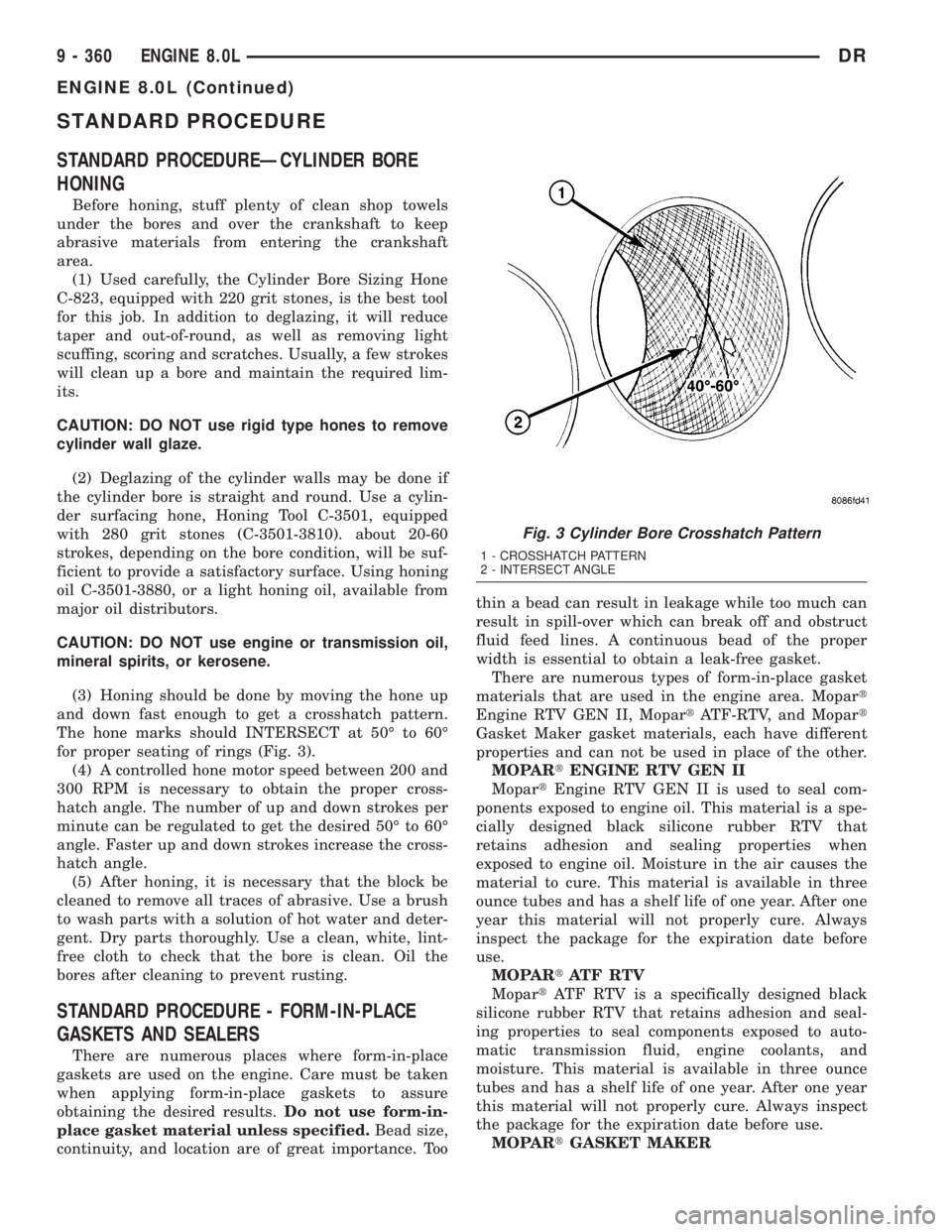
The hone marks should INTERSECT at 50É to 60É
for proper seating of rings (Fig. 3).
(4) A controlled hone motor speed between 200 and
300 RPM is necessary to obtain the proper cross-
hatch angle. The number of up and down strokes per
minute can be regulated to get the desired 50É to 60É
angle. Faster up and down strokes increase the cross-
hatch angle.
(5) After honing, it is necessary that the block be
cleaned to remove all traces of abrasive. Use a brush
to wash parts with a solution of hot water and deter-
gent. Dry parts thoroughly. Use a clean, white, lint-
free cloth to check that the bore is clean. Oil the
bores after cleaning to prevent rusting.
STANDARD PROCEDURE - FORM-IN-PLACE
GASKETS AND SEALERS
There are numerous places where form-in-place
gaskets are used on the engine. Care must be taken
when applying form-in-place gaskets to assure
obtaining the desired results.Do not use form-in-
place gasket material unless specified.Bead size,
continuity, and location are of great importance. Toothin a bead can result in leakage while too much can
result in spill-over which can break off and obstruct
fluid feed lines. A continuous bead of the proper
width is essential to obtain a leak-free gasket.
There are numerous types of form-in-place gasket
materials that are used in the engine area. Mopart
Engine RTV GEN II, MopartATF-RTV, and Mopart
Gasket Maker gasket materials, each have different
properties and can not be used in place of the other.
MOPARtENGINE RTV GEN II
MopartEngine RTV GEN II is used to seal com-
ponents exposed to engine oil. This material is a spe-
cially designed black silicone rubber RTV that
retains adhesion and sealing properties when
exposed to engine oil. Moisture in the air causes the
material to cure. This material is available in three
ounce tubes and has a shelf life of one year. After one
year this material will not properly cure. Always
inspect the package for the expiration date before
use.
MOPARtATF RTV
MopartATF RTV is a specifically designed black
silicone rubber RTV that retains adhesion and seal-
ing properties to seal components exposed to auto-
matic transmission fluid, engine coolants, and
moisture. This material is available in three ounce
tubes and has a shelf life of one year. After one year
this material will not properly cure. Always inspect
the package for the expiration date before use.
MOPARtGASKET MAKER
Fig. 3 Cylinder Bore Crosshatch Pattern
1 - CROSSHATCH PATTERN
2 - INTERSECT ANGLE
9 - 360 ENGINE 8.0LDR
ENGINE 8.0L (Continued)
Page 1611 of 2895
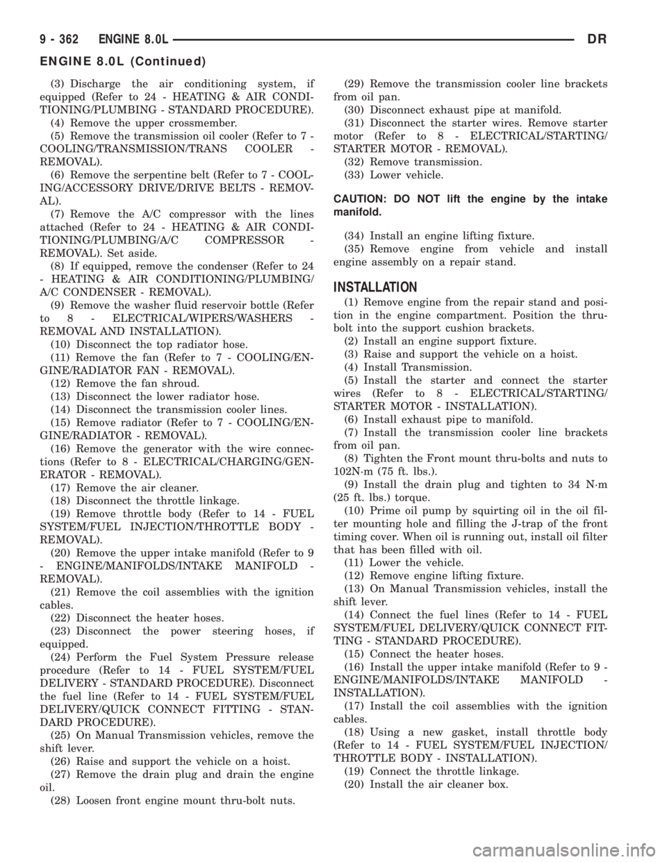
(3) Discharge the air conditioning system, if
equipped (Refer to 24 - HEATING & AIR CONDI-
TIONING/PLUMBING - STANDARD PROCEDURE).
(4) Remove the upper crossmember.
(5) Remove the transmission oil cooler (Refer to 7 -
COOLING/TRANSMISSION/TRANS COOLER -
REMOVAL).
(6) Remove the serpentine belt (Refer to 7 - COOL-
ING/ACCESSORY DRIVE/DRIVE BELTS - REMOV-
AL).
(7) Remove the A/C compressor with the lines
attached (Refer to 24 - HEATING & AIR CONDI-
TIONING/PLUMBING/A/C COMPRESSOR -
REMOVAL). Set aside.
(8) If equipped, remove the condenser (Refer to 24
- HEATING & AIR CONDITIONING/PLUMBING/
A/C CONDENSER - REMOVAL).
(9) Remove the washer fluid reservoir bottle (Refer
to 8 - ELECTRICAL/WIPERS/WASHERS -
REMOVAL AND INSTALLATION).
(10) Disconnect the top radiator hose.
(11) Remove the fan (Refer to 7 - COOLING/EN-
GINE/RADIATOR FAN - REMOVAL).
(12) Remove the fan shroud.
(13) Disconnect the lower radiator hose.
(14) Disconnect the transmission cooler lines.
(15) Remove radiator (Refer to 7 - COOLING/EN-
GINE/RADIATOR - REMOVAL).
(16) Remove the generator with the wire connec-
tions (Refer to 8 - ELECTRICAL/CHARGING/GEN-
ERATOR - REMOVAL).
(17) Remove the air cleaner.
(18) Disconnect the throttle linkage.
(19) Remove throttle body (Refer to 14 - FUEL
SYSTEM/FUEL INJECTION/THROTTLE BODY -
REMOVAL).
(20) Remove the upper intake manifold (Refer to 9
- ENGINE/MANIFOLDS/INTAKE MANIFOLD -
REMOVAL).
(21) Remove the coil assemblies with the ignition
cables.
(22) Disconnect the heater hoses.
(23) Disconnect the power steering hoses, if
equipped.
(24) Perform the Fuel System Pressure release
procedure (Refer to 14 - FUEL SYSTEM/FUEL
DELIVERY - STANDARD PROCEDURE). Disconnect
the fuel line (Refer to 14 - FUEL SYSTEM/FUEL
DELIVERY/QUICK CONNECT FITTING - STAN-
DARD PROCEDURE).
(25) On Manual Transmission vehicles, remove the
shift lever.
(26) Raise and support the vehicle on a hoist.
(27) Remove the drain plug and drain the engine
oil.
(28) Loosen front engine mount thru-bolt nuts.(29) Remove the transmission cooler line brackets
from oil pan.
(30) Disconnect exhaust pipe at manifold.
(31) Disconnect the starter wires. Remove starter
motor (Refer to 8 - ELECTRICAL/STARTING/
STARTER MOTOR - REMOVAL).
(32) Remove transmission.
(33) Lower vehicle.
CAUTION: DO NOT lift the engine by the intake
manifold.
(34) Install an engine lifting fixture.
(35) Remove engine from vehicle and install
engine assembly on a repair stand.
INSTALLATION
(1) Remove engine from the repair stand and posi-
tion in the engine compartment. Position the thru-
bolt into the support cushion brackets.
(2) Install an engine support fixture.
(3) Raise and support the vehicle on a hoist.
(4) Install Transmission.
(5) Install the starter and connect the starter
wires (Refer to 8 - ELECTRICAL/STARTING/
STARTER MOTOR - INSTALLATION).
(6) Install exhaust pipe to manifold.
(7) Install the transmission cooler line brackets
from oil pan.
(8) Tighten the Front mount thru-bolts and nuts to
102N´m (75 ft. lbs.).
(9) Install the drain plug and tighten to 34 N´m
(25 ft. lbs.) torque.
(10) Prime oil pump by squirting oil in the oil fil-
ter mounting hole and filling the J-trap of the front
timing cover. When oil is running out, install oil filter
that has been filled with oil.
(11) Lower the vehicle.
(12) Remove engine lifting fixture.
(13) On Manual Transmission vehicles, install the
shift lever.
(14) Connect the fuel lines (Refer to 14 - FUEL
SYSTEM/FUEL DELIVERY/QUICK CONNECT FIT-
TING - STANDARD PROCEDURE).
(15) Connect the heater hoses.
(16) Install the upper intake manifold (Refer to 9 -
ENGINE/MANIFOLDS/INTAKE MANIFOLD -
INSTALLATION).
(17) Install the coil assemblies with the ignition
cables.
(18) Using a new gasket, install throttle body
(Refer to 14 - FUEL SYSTEM/FUEL INJECTION/
THROTTLE BODY - INSTALLATION).
(19) Connect the throttle linkage.
(20) Install the air cleaner box.
9 - 362 ENGINE 8.0LDR
ENGINE 8.0L (Continued)
Page 1612 of 2895
(21) Install the generator and wire connections
(Refer to 8 - ELECTRICAL/CHARGING/GENERA-
TOR - INSTALLATION).
(22) Install the upper crossmember.
(23) Install radiator (Refer to 7 - COOLING/EN-
GINE/RADIATOR - INSTALLATION).
(24) Connect the lower radiator hose.
(25) Install the transmission oil cooler (Refer to 7 -
COOLING/TRANSMISSION/TRANS COOLER -
INSTALLATION).
(26) Connect the transmission cooler lines.
(27) Connect the power steering hoses, if equipped.
(28) Install the fan shroud.
(29) Install the fan (Refer to 7 - COOLING/EN-
GINE/RADIATOR FAN - INSTALLATION).
(30) Connect the top radiator hose.
(31) Install the washer fluid reservoir bottle (Refer
to 8 - ELECTRICAL/WIPERS/WASHERS - INSTAL-
LATION).
(32) If equipped, install the condenser (Refer to 24
- HEATING & AIR CONDITIONING/PLUMBING/
A/C CONDENSER - INSTALLATION).
(33) Install the A/C compressor with the lines
attached (Refer to 24 - HEATING & AIR CONDI-
TIONING/PLUMBING/A/C COMPRESSOR -
INSTALLATION).
(34) Install the serpentine belt (Refer to 7 - COOL-
ING/ACCESSORY DRIVE/DRIVE BELTS - INSTAL-
LATION).
(35) Evacuate (Refer to 24 - HEATING & AIR
CONDITIONING/PLUMBING - STANDARD PRO-
CEDURE) and charge the air conditioning system, if
equipped (Refer to 24 - HEATING & AIR CONDI-
TIONING/PLUMBING - STANDARD PROCEDURE).
(36) Add coolant to the cooling system (Refer to 7 -
COOLING - STANDARD PROCEDURE).
(37) Install the battery.
(38) Warm engine and adjust as required.
(39) Road test vehicle.SPECIFICATIONS
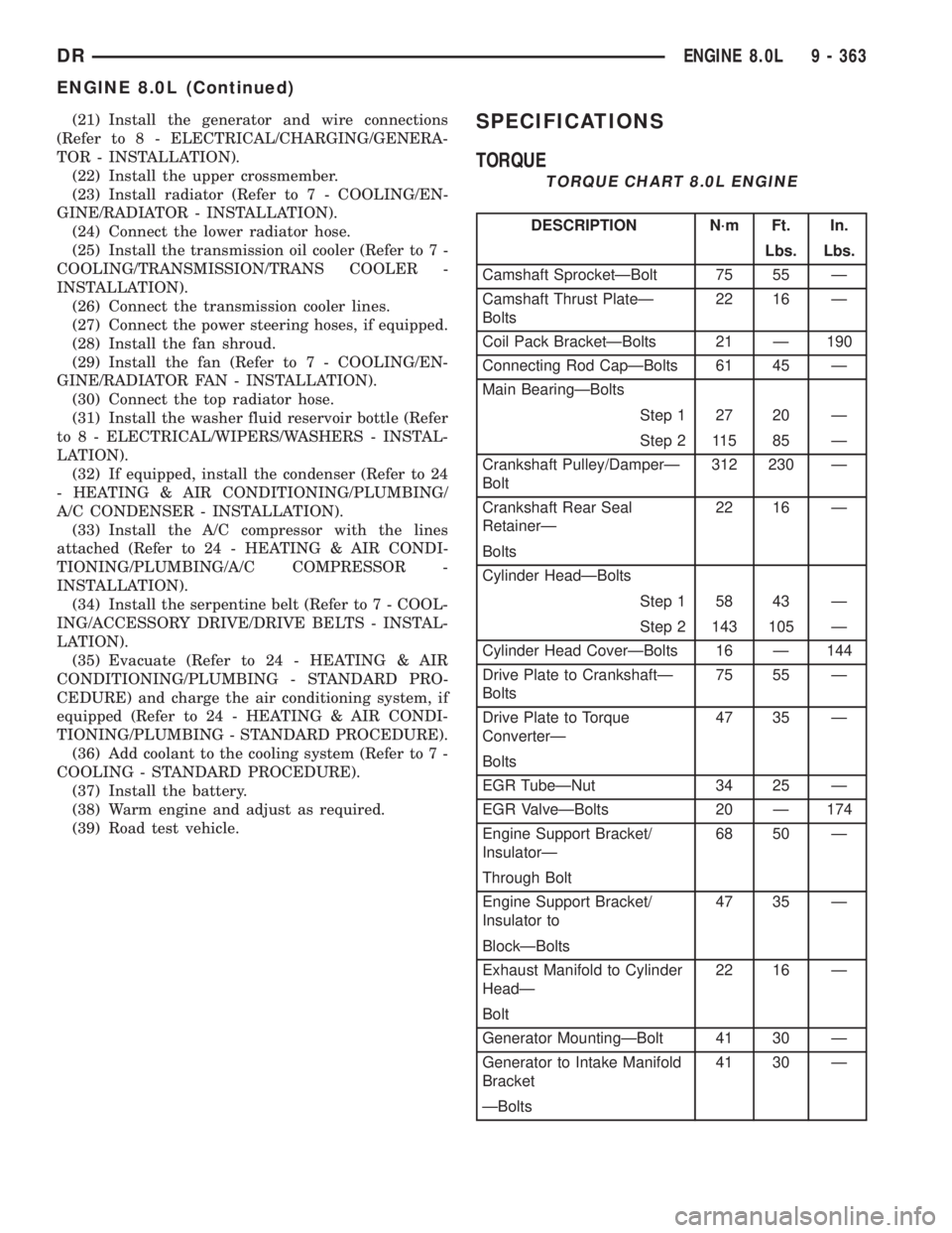
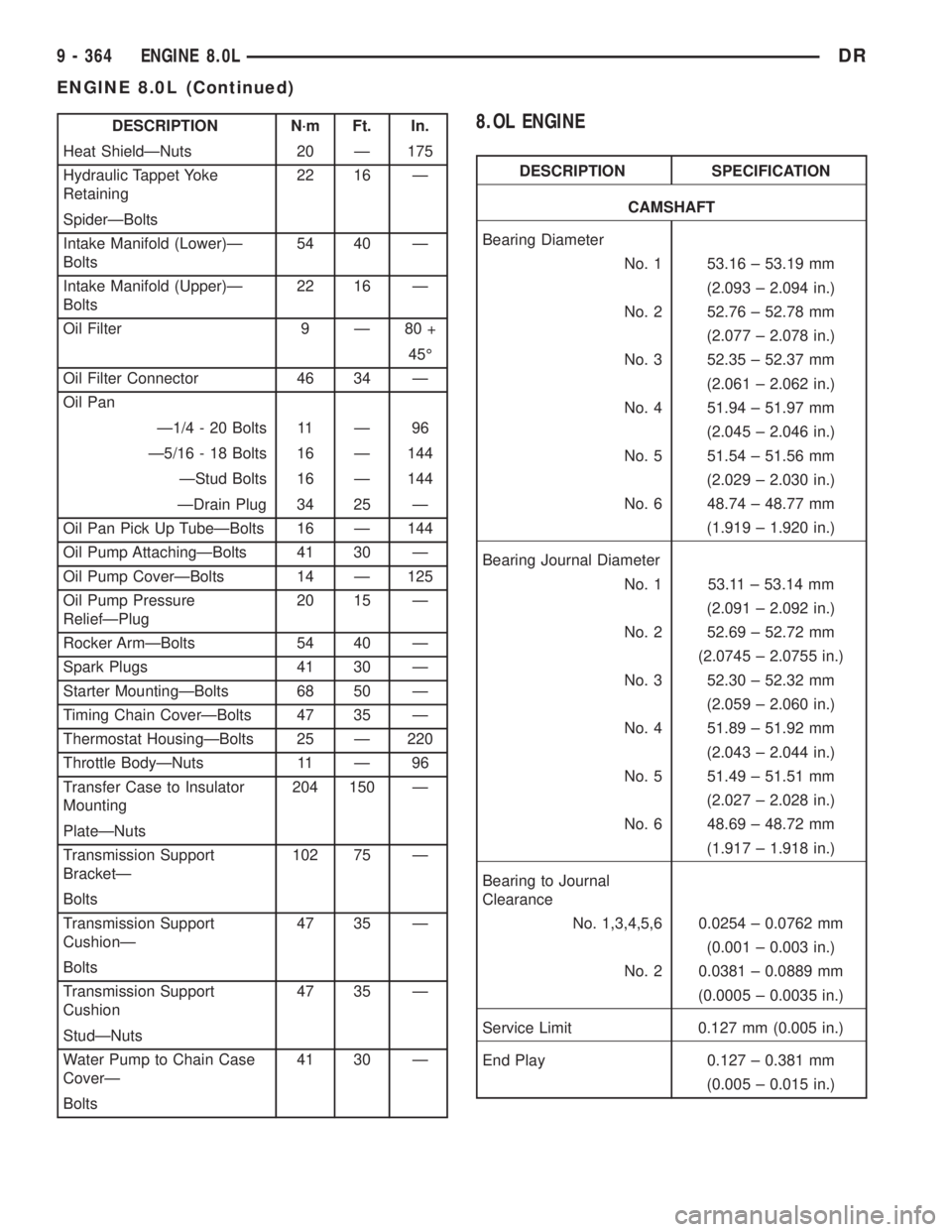
TORQUE
TORQUE CHART 8.0L ENGINE
DESCRIPTION N´m Ft. In.
Lbs. Lbs.
Camshaft SprocketÐBolt 75 55 Ð
Camshaft Thrust PlateÐ
Bolts22 16 Ð
Coil Pack BracketÐBolts 21 Ð 190
Connecting Rod CapÐBolts 61 45 Ð
Main BearingÐBolts
Step 1 27 20 Ð
Step 2 115 85 Ð
Crankshaft Pulley/DamperÐ
Bolt312 230 Ð
Crankshaft Rear Seal
RetainerÐ22 16 Ð
Bolts
Cylinder HeadÐBolts
Step 1 58 43 Ð
Step 2 143 105 Ð
Cylinder Head CoverÐBolts 16 Ð 144
Drive Plate to CrankshaftÐ
Bolts75 55 Ð
Drive Plate to Torque
ConverterÐ47 35 Ð
Bolts
EGR TubeÐNut 34 25 Ð
EGR ValveÐBolts 20 Ð 174
Engine Support Bracket/
InsulatorÐ68 50 Ð
Through Bolt
Engine Support Bracket/
Insulator to47 35 Ð
BlockÐBolts
Exhaust Manifold to Cylinder
HeadÐ22 16 Ð
Bolt
Generator MountingÐBolt 41 30 Ð
Generator to Intake Manifold
Bracket41 30 Ð
ÐBolts
DRENGINE 8.0L 9 - 363
ENGINE 8.0L (Continued)
Page 1613 of 2895
DESCRIPTION N´m Ft. In.
Heat ShieldÐNuts 20 Ð 175
Hydraulic Tappet Yoke
Retaining22 16 Ð
SpiderÐBolts
Intake Manifold (Lower)Ð
Bolts54 40 Ð
Intake Manifold (Upper)Ð
Bolts22 16 Ð
Oil Filter 9 Ð 80 +
45É
Oil Filter Connector 46 34 Ð
Oil Pan
Ð1/4 - 20 Bolts 11 Ð 96
Ð5/16 - 18 Bolts 16 Ð 144
ÐStud Bolts 16 Ð 144
ÐDrain Plug 34 25 Ð
Oil Pan Pick Up TubeÐBolts 16 Ð 144
Oil Pump AttachingÐBolts 41 30 Ð
Oil Pump CoverÐBolts 14 Ð 125
Oil Pump Pressure
ReliefÐPlug20 15 Ð
Rocker ArmÐBolts 54 40 Ð
Spark Plugs 41 30 Ð
Starter MountingÐBolts 68 50 Ð
Timing Chain CoverÐBolts 47 35 Ð
Thermostat HousingÐBolts 25 Ð 220
Throttle BodyÐNuts 11 Ð 96
Transfer Case to Insulator
Mounting204 150 Ð
PlateÐNuts
Transmission Support
BracketÐ102 75 Ð
Bolts
Transmission Support
CushionÐ47 35 Ð
Bolts
Transmission Support
Cushion47 35 Ð
StudÐNuts
Water Pump to Chain Case
CoverÐ41 30 Ð
Bolts8.OL ENGINE
DESCRIPTION SPECIFICATION
CAMSHAFT
Bearing Diameter
No. 1 53.16 ± 53.19 mm
(2.093 ± 2.094 in.)
No. 2 52.76 ± 52.78 mm
(2.077 ± 2.078 in.)
No. 3 52.35 ± 52.37 mm
(2.061 ± 2.062 in.)
No. 4 51.94 ± 51.97 mm
(2.045 ± 2.046 in.)
No. 5 51.54 ± 51.56 mm
(2.029 ± 2.030 in.)
No. 6 48.74 ± 48.77 mm
(1.919 ± 1.920 in.)
Bearing Journal Diameter
No. 1 53.11 ± 53.14 mm
(2.091 ± 2.092 in.)
No. 2 52.69 ± 52.72 mm
(2.0745 ± 2.0755 in.)
No. 3 52.30 ± 52.32 mm
(2.059 ± 2.060 in.)
No. 4 51.89 ± 51.92 mm
(2.043 ± 2.044 in.)
No. 5 51.49 ± 51.51 mm
(2.027 ± 2.028 in.)
No. 6 48.69 ± 48.72 mm
(1.917 ± 1.918 in.)
Bearing to Journal
Clearance
No. 1,3,4,5,6 0.0254 ± 0.0762 mm
(0.001 ± 0.003 in.)
No. 2 0.0381 ± 0.0889 mm
(0.0005 ± 0.0035 in.)
Service Limit 0.127 mm (0.005 in.)
End Play 0.127 ± 0.381 mm
(0.005 ± 0.015 in.)
9 - 364 ENGINE 8.0LDR
ENGINE 8.0L (Continued)
Page 1621 of 2895
fuel line (Refer to 14 - FUEL SYSTEM/FUEL DELIV-
ERY/QUICK CONNECT FITTING - STANDARD
PROCEDURE).
(9) Disconnect accelerator linkage and if so
equipped, the speed control and transmission kick-
down cables.
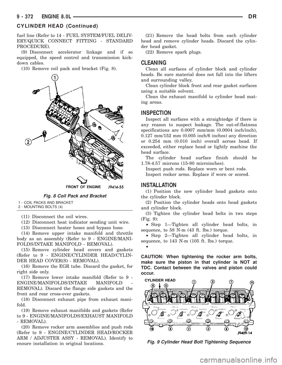
(10) Remove coil pack and bracket (Fig. 8).
(11) Disconnect the coil wires.
(12) Disconnect heat indicator sending unit wire.
(13) Disconnect heater hoses and bypass hose.
(14) Remove upper intake manifold and throttle
body as an assembly (Refer to 9 - ENGINE/MANI-
FOLDS/INTAKE MANIFOLD - REMOVAL).
(15) Remove cylinder head covers and gaskets
(Refer to 9 - ENGINE/CYLINDER HEAD/CYLIN-
DER HEAD COVER(S) - REMOVAL).
(16) Remove the EGR tube. Discard the gasket, for
right side only.
(17) Remove lower intake manifold (Refer to 9 -
ENGINE/MANIFOLDS/INTAKE MANIFOLD -
REMOVAL). Discard the flange side gaskets and the
front and rear cross-over gaskets.
(18) Disconnect exhaust pipe from exhaust mani-
fold.
(19) Remove exhaust manifolds and gaskets (Refer
to 9 - ENGINE/MANIFOLDS/EXHAUST MANIFOLD
- REMOVAL).
(20) Remove rocker arm assemblies and push rods
(Refer to 9 - ENGINE/CYLINDER HEAD/ROCKER
ARM / ADJUSTER ASSY - REMOVAL). Identify to
ensure installation in original locations.(21) Remove the head bolts from each cylinder
head and remove cylinder heads. Discard the cylin-
der head gasket.
(22) Remove spark plugs.
CLEANING
Clean all surfaces of cylinder block and cylinder
heads. Be sure material does not fall into the lifters
and surrounding valley.
Clean cylinder block front and rear gasket surfaces
using a suitable solvent.
Clean the exhaust manifold to cylinder head mat-
ing areas.
INSPECTION
Inspect all surfaces with a straightedge if there is
any reason to suspect leakage. The out-of-flatness
specifications are 0.0007 mm/mm (0.0004 inch/inch),
0.127 mm/152 mm (0.005 inch/6 inches) any direction
or 0.254 mm (0.010 inch) overall across head. If
exceeded, either replace head or lightly machine the
head surface.
The cylinder head surface finish should be
1.78-4.57 microns (15-80 microinches).
Inspect push rods. Replace worn or bent rods.
Inspect rocker arms. Replace if worn or scored.
INSTALLATION
(1) Position the new cylinder head gaskets onto
the cylinder block.
(2) Position the cylinder heads onto head gaskets
and cylinder block.
(3) Tighten the cylinder head bolts in two steps
(Fig. 9):
²Step 1ÐTighten all cylinder head bolts, in
sequence, to 58 N´m (43 ft. lbs.) torque.
²Step 2ÐTighten all cylinder head bolts, in
sequence, to 143 N´m (105 ft. lbs.) torque.
²
CAUTION: When tightening the rocker arm bolts,
make sure the piston in that cylinder is NOT at
TDC. Contact between the valves and piston could
occur.
Fig. 8 Coil Pack and Bracket
1 - COIL PACKS AND BRACKET
2 - MOUNTING BOLTS (4)
Fig. 9 Cylinder Head Bolt Tightening Sequence
9 - 372 ENGINE 8.0LDR
CYLINDER HEAD (Continued)