2003 DODGE RAM transmission
[x] Cancel search: transmissionPage 1652 of 2895

(2) Insert MopartGEN II Silicone Rubber Adhe-
sive Sealant, or equivalent, into the four corner joints
an excessive amount of sealant is not required to
ensure a leak proof seal. However, an excessive
amount of sealant may reduce the effectiveness of
the flange gasket. The sealant should be approxi-
mately 5 mm (0.2 in.) in diameter. (Fig. 70).
(3) Position the cross-over gaskets and press firmly
onto the block (Fig. 70).BE SURE THE BLOCK IS
OIL FREE..
(4) The lower intake manifold MUST be installed
within 3 minutes of sealant application. Carefully
lower intake manifold into position on the cylinder
block and heads. After intake manifold is in place,
inspect to make sure seals and gaskets are in place.
Finger start all the lower intake bolts.
(5) Tighten the lower intake manifold bolts in
sequence to 54 N´m (40 ft. lbs.) torque (Fig. 69).
Recheck all bolts are tightened to 54 N´m (40 ft. lbs.)
torque.
(6) Using a new gasket, position the upper intake
manifold onto the lower intake manifold.
(7) Finger start all bolts, alternate one side to the
other.
(8) Tighten upper intake manifold bolts in
sequence to 22 N´m (16 ft. lbs.) torque (Fig. 68).
(9) Using a new gasket, install the throttle body
onto the upper intake manifold. Tighten the bolts to
23 N´m (200 in. lbs.) torque.
(10) Install closed crankcase ventilation and evap-
oration control systems.
(11) Connect the heater hoses and bypass hose.
(12) Connect the vacuum lines.
(13) Install the coil assemblies and the ignition
wires.
(14) Connect the accelerator linkage and if so
equipped, the speed control and transmission kick-
down cables.(15) Install the fuel lines (Refer to 14 - FUEL SYS-
TEM/FUEL DELIVERY/QUICK CONNECT FIT-
TING - STANDARD PROCEDURE).
(16) Using a new gasket, install the air cleaner
housing. Tighten the nuts to 11 N´m (96 in. lbs.)
torque. Install the air cleaner filter and cover.
(17) Install the A/C compressor (Refer to 24 -
HEATING & AIR CONDITIONING/PLUMBING/A/C
COMPRESSOR - INSTALLATION). Position the com-
pressor brace and install the bolts. Tighten the brace
bolts to 41 N´m (30 ft. lbs.) torque.
(18) Install the generator (Refer to 8 - ELECTRI-
CAL/CHARGING/GENERATOR - INSTALLATION).
Position the generator brace and install the bolts.
Tighten the brace bolts to 41 N´m (30 ft. lbs.) torque.
(19) Install the accessory drive belt (Refer to 7 -
COOLING/ACCESSORY DRIVE/DRIVE BELTS -
INSTALLATION).
(20) Fill cooling system (Refer to 7 - COOLING -
STANDARD PROCEDURE).
(21) Connect the negative cable to the battery.
(22) Start engine check for leaks.
EXHAUST MANIFOLD
DESCRIPTION
Engine exhaust manifolds (Fig. 72) are made of
high molybdenum ductile cast iron. A special ribbed
design helps control permanent dimensional changes
during heat cycles.
OPERATION
The exhaust manifolds collect the engine exhaust
exiting the combustion chambers, then channels the
exhaust gases to the exhaust pipes attached to the
manifolds.
Fig. 71 Intake Manifold Flange
1 - LOCATOR DOWELS
2 - INTAKE MANIFOLD GASKETS
3 - LOCATOR DOWELS
Fig. 72 Exhaust ManifoldÐ8.0L Engine
1 - EXHAUST MANIFOLD
DRENGINE 8.0L 9 - 403
INTAKE MANIFOLD (Continued)
Page 1662 of 2895
INSTALLATION
(1) Connect the exhaust pipe(s) to the exhaust
manifold. Tighten the nuts to 34 N´m (25 ft. lbs.)
torque.
(2) Align and connect the exhaust pipe to the cat-
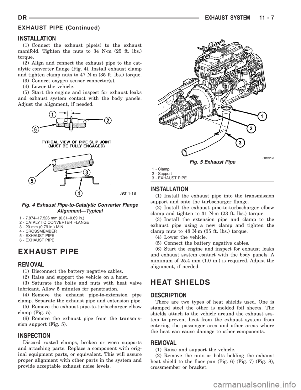
alytic converter flange (Fig. 4). Install exhaust clamp
and tighten clamp nuts to 47 N´m (35 ft. lbs.) torque.
(3) Connect oxygen sensor connector(s).
(4) Lower the vehicle.
(5) Start the engine and inspect for exhaust leaks
and exhaust system contact with the body panels.
Adjust the alignment, if needed.
EXHAUST PIPE
REMOVAL
(1) Disconnect the battery negative cables.
(2) Raise and support the vehicle on a hoist.
(3) Saturate the bolts and nuts with heat valve
lubricant. Allow 5 minutes for penetration.
(4) Remove the exhaust pipe-to-extension pipe
clamp. Separate the exhaust pipe and extension pipe.
(5) Remove the exhaust pipe-to-turbocharger elbow
clamp (Fig. 5).
(6) Remove the exhaust pipe from the transmis-
sion support (Fig. 5).
INSPECTION
Discard rusted clamps, broken or worn supports
and attaching parts. Replace a component with orig-
inal equipment parts, or equivalent. This will assure
proper alignment with other parts in the system and
provide acceptable exhaust noise levels.
INSTALLATION
(1) Install the exhaust pipe into the transmission
support and onto the turbocharger flange.
(2) Install the exhaust pipe-to-turbocharger elbow
clamp and tighten to 31 N´m (23 ft. lbs.) torque.
(3) Install the extension pipe and clamp to the
exhaust pipe using a new clamp and tighten the
clamp nuts to 48 N´m (35 ft. lbs.) torque.
(4) Lower the vehicle.
(5) Connect the battery negative cables.
(6) Start the engine and inspect for exhaust leaks
and exhaust system contact with the body panels. A
minimum of 25.4 mm (1.0 in.) is required. Adjust the
alignment, if needed.
HEAT SHIELDS
DESCRIPTION
There are two types of heat shields used. One is
stamped steel the other is molded foil sheets. The
shields attach to the vehicle around the exhaust sys-
tem to prevent heat from the exhaust system from
entering the passenger area and other areas where
the heat can cause damage to other components.
REMOVAL
(1) Raise and support the vehicle.
(2) Remove the nuts or bolts holding the exhaust
heat shield to the floor pan (Fig. 6) (Fig. 7) (Fig. 8),
crossmember or bracket.
Fig. 4 Exhaust Pipe-to-Catalytic Converter Flange
AlignmentÐTypical
1 - 7.874±17.526 mm (0.31±0.69 in.)
2 - CATALYTIC CONVERTER FLANGE
3 - 20 mm (0.79 in.) MIN.
4 - CROSSMEMBER
5 - EXHAUST PIPE
6 - EXHAUST PIPE
Fig. 5 Exhaust Pipe
1 - Clamp
2 - Support
3 - EXHAUST PIPE
DREXHAUST SYSTEM 11 - 7
EXHAUST PIPE (Continued)
Page 1671 of 2895
(1) Disconnect the battery negative cables.
(2) Discharge the A/C system (Refer to 24 - HEAT-
ING & AIR CONDITIONING/PLUMBING - STAN-
DARD PROCEDURE) and remove the A/C condenser
(Refer to 24 - HEATING & AIR CONDITIONING/
PLUMBING/A/C CONDENSER - REMOVAL) (if A/C
equipped).
(3) Remove the transmission auxiliary cooler
(Refer to 7 - COOLING/TRANSMISSION/TRANS
COOLER - REMOVAL).
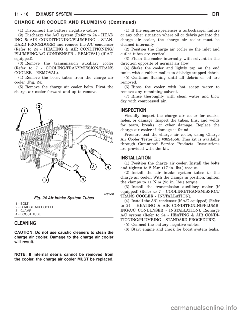
(4) Remove the boost tubes from the charge air
cooler (Fig. 24).
(5) Remove the charge air cooler bolts. Pivot the
charge air cooler forward and up to remove.
CLEANING
CAUTION: Do not use caustic cleaners to clean the
charge air cooler. Damage to the charge air cooler
will result.
NOTE: If internal debris cannot be removed from
the cooler, the charge air cooler MUST be replaced.(1) If the engine experiences a turbocharger failure
or any other situation where oil or debris get into the
charge air cooler, the charge air cooler must be
cleaned internally.
(2) Position the charge air cooler so the inlet and
outlet tubes are vertical.
(3) Flush the cooler internally with solvent in the
direction opposite of normal air flow.
(4)
Shake the cooler and lightly tap on the end
tanks with a rubber mallet to dislodge trapped debris.
(5) Continue flushing until all debris or oil are
removed.
(6) Rinse the cooler with hot soapy water to
remove any remaining solvent.
(7) Rinse thoroughly with clean water and blow
dry with compressed air.
INSPECTION
Visually inspect the charge air cooler for cracks,
holes, or damage. Inspect the tubes, fins, and welds
for tears, breaks, or other damage. Replace the
charge air cooler if damage is found.
Pressure test the charge air cooler, using Charge
Air Cooler Tester Kit #3824556. This kit is available
through CumminstService Products. Instructions
are provided with the kit.
INSTALLATION
(1) Position the charge air cooler. Install the bolts
and tighten to 2 N´m (17 in. lbs.) torque.
(2) Install the air intake system tubes to the
charge air cooler. With the clamps in position, tighten
the clamps to 11 N´m (95 in. lbs.) torque.
(3) Install the transmission auxiliary cooler (if
equipped) (Refer to 7 - COOLING/TRANSMISSION/
TRANS COOLER - INSTALLATION).
(4)
Install the A/C condenser (if A/C equipped) (Refer
to 24 - HEATING & AIR CONDITIONING/PLUMB-
ING/A/C CONDENSER - INSTALLATION). Recharge
A/C system (Refer to 24 - HEATING & AIR CONDI-
TIONING/PLUMBING - STANDARD PROCEDURE).
(5) Connect the battery negative cables.
(6) Start engine and check for boost system leaks.
Fig. 24 Air Intake System Tubes
1 - BOLT
2 - CHARGE AIR COOLER
3 - CLAMP
4 - BOOST TUBE
11 - 16 EXHAUST SYSTEMDR
CHARGE AIR COOLER AND PLUMBING (Continued)
Page 1672 of 2895
FRAMES & BUMPERS
TABLE OF CONTENTS
page page
BUMPERS
SPECIFICATIONS - TORQUE...............1
FRONT AIR DAM
REMOVAL.............................2
INSTALLATION..........................2
FRONT BUMPER
REMOVAL.............................2
INSTALLATION..........................2
FRONT FASCIA
REMOVAL.............................3
INSTALLATION..........................3
REAR BUMPER
REMOVAL.............................4
INSTALLATION..........................4
FRAME
STANDARD PROCEDURE
STANDARD PROCEDURE - LIGHT DUTY
FRONT FRAME RAIL TIP REPLACEMENT....4
STANDARD PROCEDURE - HYDROFORM
FENDER RAIL REPAIR.................12
STANDARD PROCEDURE - REAR FRAME
H-SECTION REPLACEMENT.............15SPECIFICATIONS
SPECIFICATIONS - FRAME DIMENSIONS . . . 17
SPECIFICATIONS - TORQUE............23
FRONT CROSSMEMBER
REMOVAL.............................23
INSTALLATION.........................23
FRONT SKID PLATE
REMOVAL.............................24
INSTALLATION.........................24
TRANSMISSION CROSSMEMBER
REMOVAL.............................24
INSTALLATION.........................25
TRAILER HITCH
REMOVAL.............................25
INSTALLATION.........................25
TRANSFER CASE SKID PLATE
REMOVAL.............................26
INSTALLATION.........................26
FRONT TOW HOOK ASSEMBLY
REMOVAL.............................26
INSTALLATION.........................26
BUMPERS
SPECIFICATIONS - TORQUE
TORQUE SPECIFICATIONS
DESCRIPTION N´m Ft. Lbs. In. Lbs.
Front bumper center bracket nuts 95 70 Ð
Front bumper stud plate nuts 95 70 Ð
License plate hitch reinforcement bolts 54 40 Ð
Rear bumper support bracket stud plate nuts 54 40 Ð
Rear bumper support bracket to hitch bolts 54 40 Ð
Rear bumper to hitch bolts 54 40 Ð
DRFRAMES & BUMPERS 13 - 1
Page 1694 of 2895
SPECIFICATIONS - TORQUE
TORQUE SPECIFICATIONS
DESCRIPTION N´m Ft. Lbs. In. Lbs.
Cab mount bolts 81 60 Ð
Cargo box bolts 108 80 Ð
Front crossmember bolts - 2WD 61 45 Ð
Front crossmember bolts - 4WD 102 75 Ð
Front skid plate bolts 34 25 Ð
Lower bumper support bracket bolt 54 40 Ð
Radiator crossmember bolts - lower 28 21 Ð
Radiator crossmember bolts - upper 28 21 Ð
Rear crossmember - 2WD 102 75 Ð
Rear crossmember - 4WD 102 75 Ð
Rear spring shackle bolts 163 120 Ð
Spare tire winch bolts 41 30 Ð
Trailer hitch reinforcement bracket bolt 170 125 Ð
Transfercase skid plate bolts 34 25 Ð
Transercase skid plate crossmember bolts 34 25 Ð
Transmission mount to crossmember nuts 61 45 Ð
FRONT CROSSMEMBER
REMOVAL
(1) Raise and support the vehicle. (Refer to
LUBRICATION & MAINTENANCE/HOISTING -
STANDARD PROCEDURE)
(2) Remove the front skid plate, if equipped. (Refer
to 13 - FRAME & BUMPERS/FRAME/FRONT SKID
PLATE - REMOVAL)
(3) Remove the bolts and remove the crossmember.
(Fig. 29) or (Fig. 30)
INSTALLATION
(1) Install the crossmember.
(2) Install the bolts;
²On 2WD vehicles, tighten the bolts to 61 N´m
(45 ft. lbs.).
²On 4WD vehicles, tighten the bolts to 102 N´m
(75 ft. lbs.).
Fig. 29 FRONT CROSSMEMBER - 2WD
1 - CROSSMEMBER
2 - BOLTS (2 PER SIDE)
DRFRAMES & BUMPERS 13 - 23
FRAME (Continued)
Page 1695 of 2895
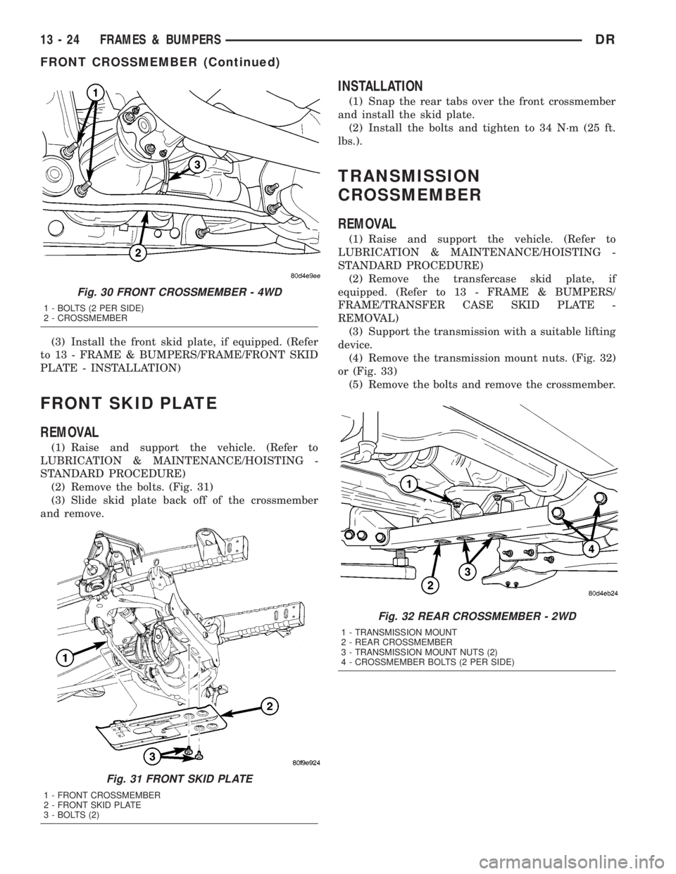
(3) Install the front skid plate, if equipped. (Refer
to 13 - FRAME & BUMPERS/FRAME/FRONT SKID
PLATE - INSTALLATION)
FRONT SKID PLATE
REMOVAL
(1) Raise and support the vehicle. (Refer to
LUBRICATION & MAINTENANCE/HOISTING -
STANDARD PROCEDURE)
(2) Remove the bolts. (Fig. 31)
(3) Slide skid plate back off of the crossmember
and remove.
INSTALLATION
(1) Snap the rear tabs over the front crossmember
and install the skid plate.
(2) Install the bolts and tighten to 34 N´m (25 ft.
lbs.).
TRANSMISSION
CROSSMEMBER
REMOVAL
(1) Raise and support the vehicle. (Refer to
LUBRICATION & MAINTENANCE/HOISTING -
STANDARD PROCEDURE)
(2) Remove the transfercase skid plate, if
equipped. (Refer to 13 - FRAME & BUMPERS/
FRAME/TRANSFER CASE SKID PLATE -
REMOVAL)
(3) Support the transmission with a suitable lifting
device.
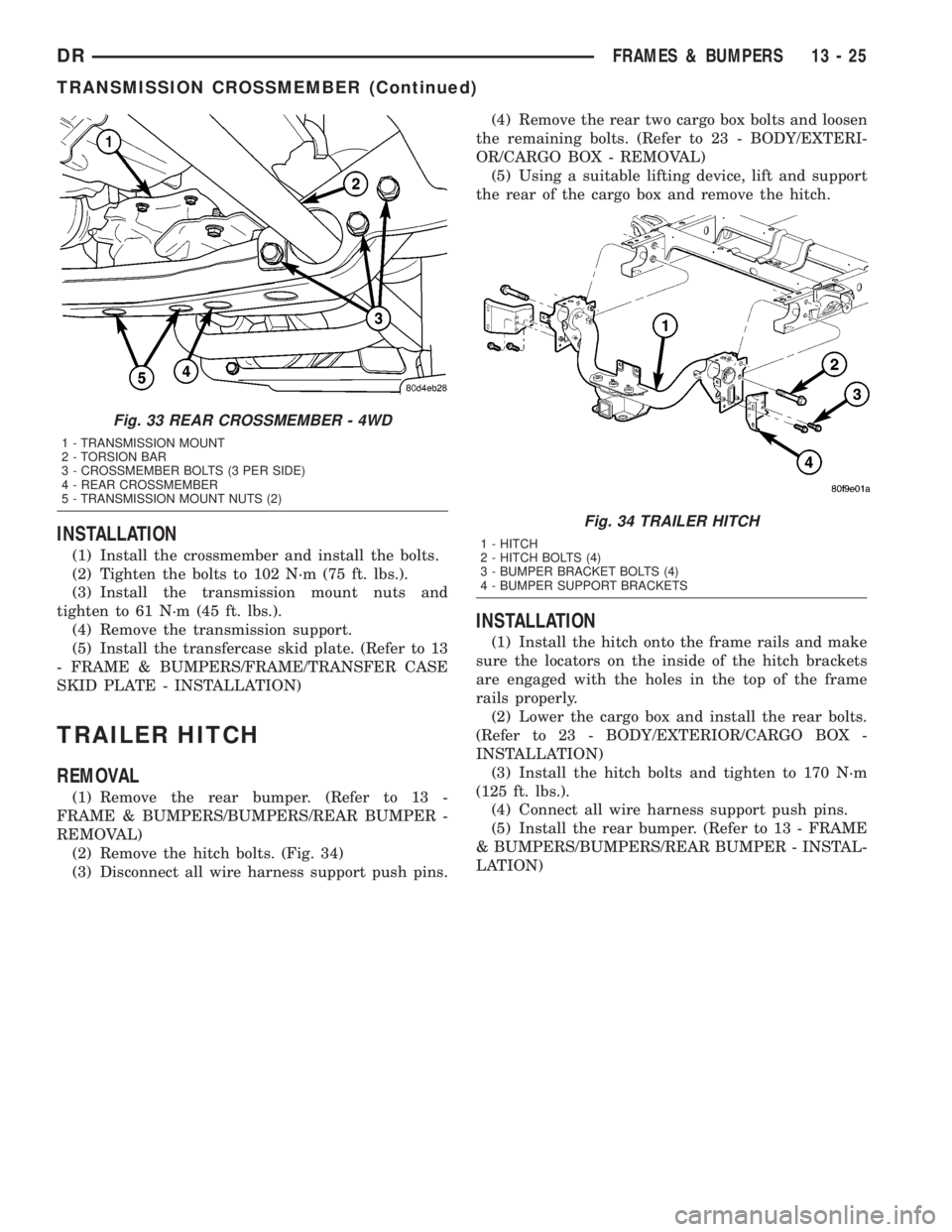
(4) Remove the transmission mount nuts. (Fig. 32)
or (Fig. 33)
(5) Remove the bolts and remove the crossmember.
Fig. 30 FRONT CROSSMEMBER - 4WD
1 - BOLTS (2 PER SIDE)
2 - CROSSMEMBER
Fig. 31 FRONT SKID PLATE
1 - FRONT CROSSMEMBER
2 - FRONT SKID PLATE
3 - BOLTS (2)
Fig. 32 REAR CROSSMEMBER - 2WD
1 - TRANSMISSION MOUNT
2 - REAR CROSSMEMBER
3 - TRANSMISSION MOUNT NUTS (2)
4 - CROSSMEMBER BOLTS (2 PER SIDE)
13 - 24 FRAMES & BUMPERSDR
FRONT CROSSMEMBER (Continued)
Page 1696 of 2895
INSTALLATION
(1) Install the crossmember and install the bolts.
(2) Tighten the bolts to 102 N´m (75 ft. lbs.).
(3) Install the transmission mount nuts and
tighten to 61 N´m (45 ft. lbs.).
(4) Remove the transmission support.
(5) Install the transfercase skid plate. (Refer to 13
- FRAME & BUMPERS/FRAME/TRANSFER CASE
SKID PLATE - INSTALLATION)
TRAILER HITCH
REMOVAL
(1) Remove the rear bumper. (Refer to 13 -
FRAME & BUMPERS/BUMPERS/REAR BUMPER -
REMOVAL)
(2) Remove the hitch bolts. (Fig. 34)
(3) Disconnect all wire harness support push pins.(4) Remove the rear two cargo box bolts and loosen
the remaining bolts. (Refer to 23 - BODY/EXTERI-
OR/CARGO BOX - REMOVAL)
(5) Using a suitable lifting device, lift and support
the rear of the cargo box and remove the hitch.
INSTALLATION
(1) Install the hitch onto the frame rails and make
sure the locators on the inside of the hitch brackets
are engaged with the holes in the top of the frame
rails properly.
(2) Lower the cargo box and install the rear bolts.
(Refer to 23 - BODY/EXTERIOR/CARGO BOX -
INSTALLATION)
(3) Install the hitch bolts and tighten to 170 N´m
(125 ft. lbs.).
(4) Connect all wire harness support push pins.
(5) Install the rear bumper. (Refer to 13 - FRAME
& BUMPERS/BUMPERS/REAR BUMPER - INSTAL-
LATION)
Fig. 33 REAR CROSSMEMBER - 4WD
1 - TRANSMISSION MOUNT
2 - TORSION BAR
3 - CROSSMEMBER BOLTS (3 PER SIDE)
4 - REAR CROSSMEMBER
5 - TRANSMISSION MOUNT NUTS (2)
Fig. 34 TRAILER HITCH
1 - HITCH
2 - HITCH BOLTS (4)
3 - BUMPER BRACKET BOLTS (4)
4 - BUMPER SUPPORT BRACKETS
DRFRAMES & BUMPERS 13 - 25
TRANSMISSION CROSSMEMBER (Continued)
Page 1727 of 2895
5.9L Gas
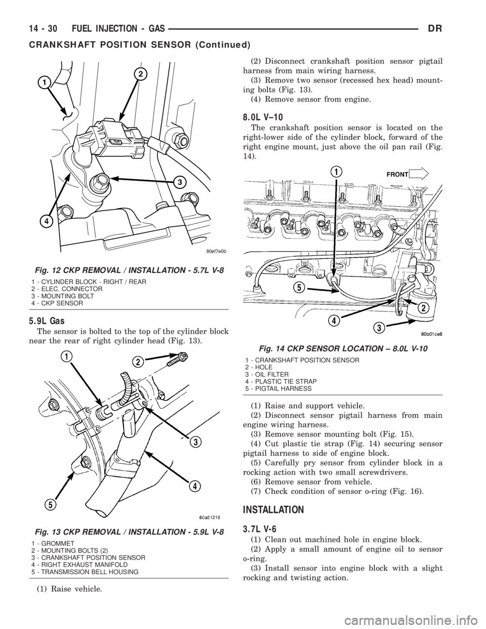
The sensor is bolted to the top of the cylinder block
near the rear of right cylinder head (Fig. 13).
(1) Raise vehicle.(2) Disconnect crankshaft position sensor pigtail
harness from main wiring harness.
(3) Remove two sensor (recessed hex head) mount-
ing bolts (Fig. 13).
(4) Remove sensor from engine.
8.0L V±10
The crankshaft position sensor is located on the
right-lower side of the cylinder block, forward of the
right engine mount, just above the oil pan rail (Fig.
14).
(1) Raise and support vehicle.
(2) Disconnect sensor pigtail harness from main
engine wiring harness.
(3) Remove sensor mounting bolt (Fig. 15).
(4) Cut plastic tie strap (Fig. 14) securing sensor
pigtail harness to side of engine block.
(5) Carefully pry sensor from cylinder block in a
rocking action with two small screwdrivers.
(6) Remove sensor from vehicle.
(7) Check condition of sensor o-ring (Fig. 16).
INSTALLATION
3.7L V-6
(1) Clean out machined hole in engine block.
(2) Apply a small amount of engine oil to sensor
o-ring.
(3) Install sensor into engine block with a slight
rocking and twisting action.
Fig. 12 CKP REMOVAL / INSTALLATION - 5.7L V-8
1 - CYLINDER BLOCK - RIGHT / REAR
2 - ELEC. CONNECTOR
3 - MOUNTING BOLT
4 - CKP SENSOR
Fig. 13 CKP REMOVAL / INSTALLATION - 5.9L V-8
1 - GROMMET
2 - MOUNTING BOLTS (2)
3 - CRANKSHAFT POSITION SENSOR
4 - RIGHT EXHAUST MANIFOLD
5 - TRANSMISSION BELL HOUSING
Fig. 14 CKP SENSOR LOCATION ± 8.0L V-10
1 - CRANKSHAFT POSITION SENSOR
2 - HOLE
3 - OIL FILTER
4 - PLASTIC TIE STRAP
5 - PIGTAIL HARNESS
14 - 30 FUEL INJECTION - GASDR
CRANKSHAFT POSITION SENSOR (Continued)