2003 DODGE RAM Heating and cooling
[x] Cancel search: Heating and coolingPage 299 of 2895

CONDITION POSSIBLE CAUSES CORRECTION
TEMPERATURE GAUGE
READS HIGH OR THE
COOLANT WARNING LAMP
ILLUMINATES. COOLANT MAY
OR MAY NOT BE LOST OR
LEAKING FROM THE COOLING
SYSTEM1. Trailer is being towed, a steep
hill is being climbed, vehicle is
operated in slow moving traffic,
or engine is being idled with
very high ambient (outside)
temperatures and the air
conditioning is on. Higher
altitudes could aggravate these
conditions.1. This may be a temporary condition and
repair is not necessary. Turn off the air
conditioning and attempt to drive the
vehicle without any of the previous
conditions. Observe the temperature
gauge. The gauge should return to the
normal range. If the gauge does not return
to the normal range, determine the cause
for overheating and repair. Refer to
Possible Causes (2-18).
2. Is the temperature gauge
reading correctly?2. Check gauge. (Refer to 8 -
ELECTRICAL/INSTRUMENT CLUSTER -
SCHEMATIC - ELECTRICAL). Repair as
necessary.
3. Is the temperature warning
illuminating unnecessarily?3. (Refer to 8 - ELECTRICAL/
INSTRUMENT CLUSTER - SCHEMATIC -
ELECTRICAL).
4. Coolant low in coolant
reserve/overflow tank and
radiator?4. Check for coolant leaks and repair as
necessary. (Refer to 7 - COOLING -
DIAGNOSIS AND TESTING).
5. Pressure cap not installed
tightly. If cap is loose, boiling
point of coolant will be lowered.
Also refer to the following Step
6.5. Tighten cap
6. Poor seals at the radiator
cap.6. (a) Check condition of cap and cap
seals. Refer to Radiator Cap. Replace cap
if necessary.
(b) Check condition of radiator filler neck.
If neck is bent or damaged, replace
radiator (5.9L) or degas bottle (3.7L, 4.7L).
7. Coolant level low in radiator
but not in coolant reserve/
overflow tank. This means the
radiator is not drawing coolant
from the coolant reserve/
overflow tank as the engine
cools (5.9L).7. (a) Check condition of radiator cap and
cap seals. Refer to Radiator Cap in this
Group. Replace cap if necessary.
(b) Check condition of radiator filler neck.
If neck is bent or damaged, replace
radiator.
(c) Check condition of the hose from the
radiator to the coolant tank. It should fit
tight at both ends without any kinks or
tears. Replace hose if necessary.
(d) Check coolant reserve/overflow tank
and tanks hoses for blockage. Repair as
necessary.
8. Incorrect coolant
concentration8. Check coolant. (Refer to LUBRICATION
& MAINTENANCE/FLUID TYPES -
DESCRIPTION).
9. Coolant not flowing through
system9. Check for coolant flow at radiator filler
neck with some coolant removed, engine
warm and thermostat open. Coolant
should be observed flowing through
radiator. If flow is not observed, determine
area of obstruction and repair as
necessary.
7 - 12 COOLINGDR
COOLING (Continued)
Page 300 of 2895

CONDITION POSSIBLE CAUSES CORRECTION
10. Radiator or A/C condenser
fins are dirty or clogged.10. Remove insects and debris. (Refer to
7 - COOLING - STANDARD
PROCEDURE).
11. Radiator core is corroded or
plugged.11. Have radiator re-cored or replaced.
12. Fuel or ignition system
problems.12. Refer to 14 - Fuel System or 8 -
Electrical for diagnosis and testing
procedures.
13. Dragging brakes. 13. Check and correct as necessary.
(Refer to 5 - BRAKES - DIAGNOSIS AND
TESTING) for correct procedures.
14. Bug screen or cardboard is
being , reducing airflow.14. Remove bug screen or cardboard.
15. Thermostat partially or
completely shut.15. Check thermostat operation and
replace as necessary. (Refer to 7 -
COOLING/ENGINE/ENGINE COOLANT
THERMOSTAT - REMOVAL) .
16. Viscous fan drive not
operating properly.16. Check fan drive operation and replace
as necessary. (Refer to 7 - COOLING/
ENGINE/FAN DRIVE VISCOUS CLUTCH
- REMOVAL).
17. Cylinder head gasket
leaking.17. Check for cylinder head gasket leaks.
(Refer to 7 - COOLING - DIAGNOSIS
AND TESTING).
18. Heater core leaking. 18. Check heater core for leaks. (Refer to
24 - HEATING & AIR CONDITIONING/
PLUMBING - DIAGNOSIS AND
TESTING). Repair as necessary.
DRCOOLING 7 - 13
COOLING (Continued)
Page 302 of 2895
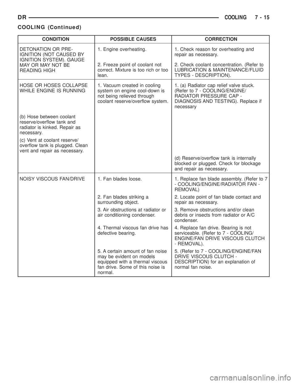
CONDITION POSSIBLE CAUSES CORRECTION
DETONATION OR PRE-
IGNITION (NOT CAUSED BY
IGNITION SYSTEM). GAUGE
MAY OR MAY NOT BE
READING HIGH1. Engine overheating. 1. Check reason for overheating and
repair as necessary.
2. Freeze point of coolant not
correct. Mixture is too rich or too
lean.2. Check coolant concentration. (Refer to
LUBRICATION & MAINTENANCE/FLUID
TYPES - DESCRIPTION).
HOSE OR HOSES COLLAPSE
WHILE ENGINE IS RUNNING1. Vacuum created in cooling
system on engine cool-down is
not being relieved through
coolant reserve/overflow system.1. (a) Radiator cap relief valve stuck.
(Refer to 7 - COOLING/ENGINE/
RADIATOR PRESSURE CAP -
DIAGNOSIS AND TESTING). Replace if
necessary
(b) Hose between coolant
reserve/overflow tank and
radiator is kinked. Repair as
necessary.
(c) Vent at coolant reserve/
overflow tank is plugged. Clean
vent and repair as necessary.
(d) Reserve/overflow tank is internally
blocked or plugged. Check for blockage
and repair as necessary.
NOISY VISCOUS FAN/DRIVE 1. Fan blades loose. 1. Replace fan blade assembly. (Refer to 7
- COOLING/ENGINE/RADIATOR FAN -
REMOVAL)
2. Fan blades striking a
surrounding object.2. Locate point of fan blade contact and
repair as necessary.
3. Air obstructions at radiator or
air conditioning condenser.3. Remove obstructions and/or clean
debris or insects from radiator or A/C
condenser.
4. Thermal viscous fan drive has
defective bearing.4. Replace fan drive. Bearing is not
serviceable. (Refer to 7 - COOLING/
ENGINE/FAN DRIVE VISCOUS CLUTCH
- REMOVAL).
5. A certain amount of fan noise
may be evident on models
equipped with a thermal viscous
fan drive. Some of this noise is
normal.5. (Refer to 7 - COOLING/ENGINE/FAN
DRIVE VISCOUS CLUTCH -
DESCRIPTION) for an explanation of
normal fan noise.
DRCOOLING 7 - 15
COOLING (Continued)
Page 303 of 2895
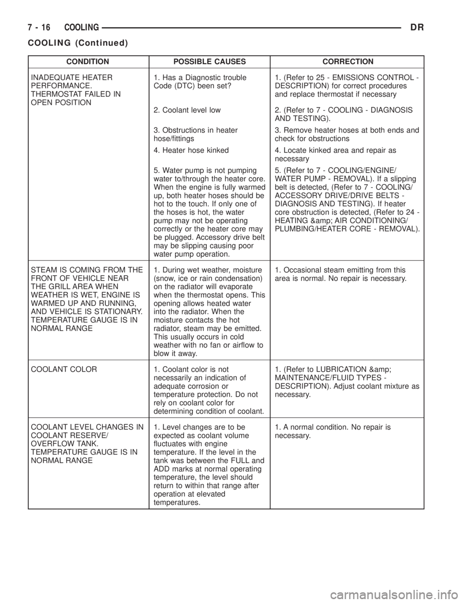
CONDITION POSSIBLE CAUSES CORRECTION
INADEQUATE HEATER
PERFORMANCE.
THERMOSTAT FAILED IN
OPEN POSITION1. Has a Diagnostic trouble
Code (DTC) been set?1. (Refer to 25 - EMISSIONS CONTROL -
DESCRIPTION) for correct procedures
and replace thermostat if necessary
2. Coolant level low 2. (Refer to 7 - COOLING - DIAGNOSIS
AND TESTING).
3. Obstructions in heater
hose/fittings3. Remove heater hoses at both ends and
check for obstructions
4. Heater hose kinked 4. Locate kinked area and repair as
necessary
5. Water pump is not pumping
water to/through the heater core.
When the engine is fully warmed
up, both heater hoses should be
hot to the touch. If only one of
the hoses is hot, the water
pump may not be operating
correctly or the heater core may
be plugged. Accessory drive belt
may be slipping causing poor
water pump operation.5. (Refer to 7 - COOLING/ENGINE/
WATER PUMP - REMOVAL). If a slipping
belt is detected, (Refer to 7 - COOLING/
ACCESSORY DRIVE/DRIVE BELTS -
DIAGNOSIS AND TESTING). If heater
core obstruction is detected, (Refer to 24 -
HEATING & AIR CONDITIONING/
PLUMBING/HEATER CORE - REMOVAL).
STEAM IS COMING FROM THE
FRONT OF VEHICLE NEAR
THE GRILL AREA WHEN
WEATHER IS WET, ENGINE IS
WARMED UP AND RUNNING,
AND VEHICLE IS STATIONARY.
TEMPERATURE GAUGE IS IN
NORMAL RANGE1. During wet weather, moisture
(snow, ice or rain condensation)
on the radiator will evaporate
when the thermostat opens. This
opening allows heated water
into the radiator. When the
moisture contacts the hot
radiator, steam may be emitted.
This usually occurs in cold
weather with no fan or airflow to
blow it away.1. Occasional steam emitting from this
area is normal. No repair is necessary.
COOLANT COLOR 1. Coolant color is not
necessarily an indication of
adequate corrosion or
temperature protection. Do not
rely on coolant color for
determining condition of coolant.1. (Refer to LUBRICATION &
MAINTENANCE/FLUID TYPES -
DESCRIPTION). Adjust coolant mixture as
necessary.
COOLANT LEVEL CHANGES IN
COOLANT RESERVE/
OVERFLOW TANK.
TEMPERATURE GAUGE IS IN
NORMAL RANGE1. Level changes are to be
expected as coolant volume
fluctuates with engine
temperature. If the level in the
tank was between the FULL and
ADD marks at normal operating
temperature, the level should
return to within that range after
operation at elevated
temperatures.1. A normal condition. No repair is
necessary.
7 - 16 COOLINGDR
COOLING (Continued)
Page 305 of 2895
CAUTION: Follow manufacturers instructions when
using these products.
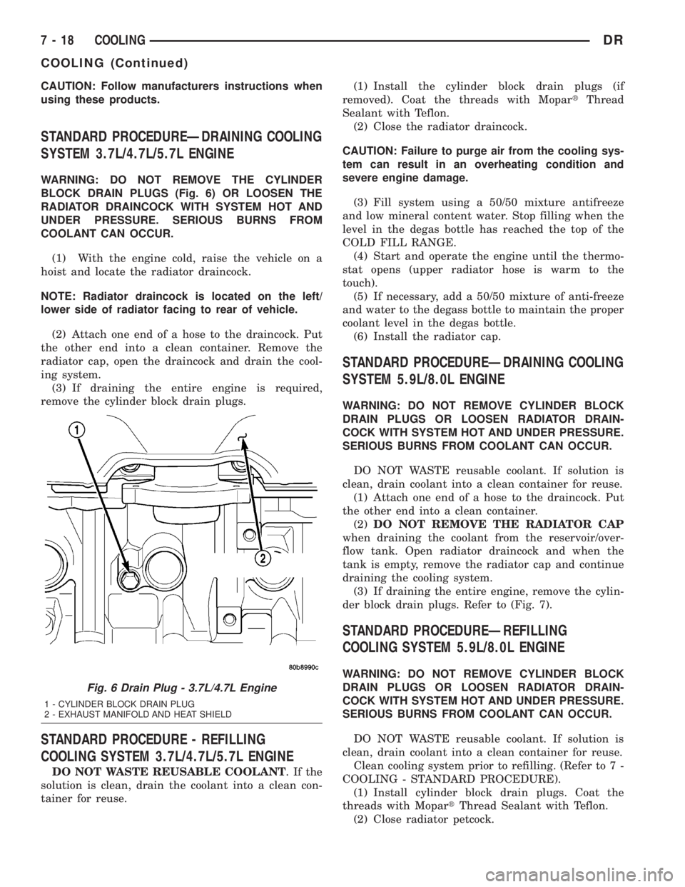
STANDARD PROCEDUREÐDRAINING COOLING
SYSTEM 3.7L/4.7L/5.7L ENGINE
WARNING: DO NOT REMOVE THE CYLINDER
BLOCK DRAIN PLUGS (Fig. 6) OR LOOSEN THE
RADIATOR DRAINCOCK WITH SYSTEM HOT AND
UNDER PRESSURE. SERIOUS BURNS FROM
COOLANT CAN OCCUR.
(1) With the engine cold, raise the vehicle on a
hoist and locate the radiator draincock.
NOTE: Radiator draincock is located on the left/
lower side of radiator facing to rear of vehicle.
(2) Attach one end of a hose to the draincock. Put
the other end into a clean container. Remove the
radiator cap, open the draincock and drain the cool-
ing system.
(3) If draining the entire engine is required,
remove the cylinder block drain plugs.
STANDARD PROCEDURE - REFILLING
COOLING SYSTEM 3.7L/4.7L/5.7L ENGINE
DO NOT WASTE REUSABLE COOLANT.Ifthe
solution is clean, drain the coolant into a clean con-
tainer for reuse.(1) Install the cylinder block drain plugs (if
removed). Coat the threads with MopartThread
Sealant with Teflon.
(2) Close the radiator draincock.
CAUTION: Failure to purge air from the cooling sys-
tem can result in an overheating condition and
severe engine damage.
(3) Fill system using a 50/50 mixture antifreeze
and low mineral content water. Stop filling when the
level in the degas bottle has reached the top of the
COLD FILL RANGE.
(4) Start and operate the engine until the thermo-
stat opens (upper radiator hose is warm to the
touch).
(5) If necessary, add a 50/50 mixture of anti-freeze
and water to the degass bottle to maintain the proper
coolant level in the degas bottle.
(6) Install the radiator cap.
STANDARD PROCEDUREÐDRAINING COOLING
SYSTEM 5.9L/8.0L ENGINE
WARNING: DO NOT REMOVE CYLINDER BLOCK
DRAIN PLUGS OR LOOSEN RADIATOR DRAIN-
COCK WITH SYSTEM HOT AND UNDER PRESSURE.
SERIOUS BURNS FROM COOLANT CAN OCCUR.
DO NOT WASTE reusable coolant. If solution is
clean, drain coolant into a clean container for reuse.
(1) Attach one end of a hose to the draincock. Put
the other end into a clean container.
(2)DO NOT REMOVE THE RADIATOR CAP
when draining the coolant from the reservoir/over-
flow tank. Open radiator draincock and when the
tank is empty, remove the radiator cap and continue
draining the cooling system.
(3) If draining the entire engine, remove the cylin-
der block drain plugs. Refer to (Fig. 7).
STANDARD PROCEDUREÐREFILLING
COOLING SYSTEM 5.9L/8.0L ENGINE
WARNING: DO NOT REMOVE CYLINDER BLOCK
DRAIN PLUGS OR LOOSEN RADIATOR DRAIN-
COCK WITH SYSTEM HOT AND UNDER PRESSURE.
SERIOUS BURNS FROM COOLANT CAN OCCUR.
DO NOT WASTE reusable coolant. If solution is
clean, drain coolant into a clean container for reuse.
Clean cooling system prior to refilling. (Refer to 7 -
COOLING - STANDARD PROCEDURE).
(1) Install cylinder block drain plugs. Coat the
threads with MopartThread Sealant with Teflon.
(2) Close radiator petcock.
Fig. 6 Drain Plug - 3.7L/4.7L Engine
1 - CYLINDER BLOCK DRAIN PLUG
2 - EXHAUST MANIFOLD AND HEAT SHIELD
7 - 18 COOLINGDR
COOLING (Continued)
Page 310 of 2895

NOTE: A used belt should be replaced if tensioner
indexing arrow has moved to the minimum tension
indicator. Tensioner travel stops at this point.
(1) Remove accessory drive belt (Refer to 7 -
COOLING/ACCESSORY DRIVE/DRIVE BELTS -
REMOVAL).
(2) Remove tensioner assembly from mounting
bracket (Fig. 2).
WARNING: BECAUSE OF HIGH SPRING PRES-
SURE, DO NOT ATTEMPT TO DISASSEMBLE AUTO-
MATIC TENSIONER. UNIT IS SERVICED AS AN
ASSEMBLY EXCEPT FOR PULLEY ON TENSIONER.
(3) Remove pulley bolt. Remove pulley from ten-
sioner.
INSTALLATION
(1) Install pulley and pulley bolt to tensioner.
Tighten bolt to 61 N´m (45 ft. lbs.) torque.
(2) An indexing slot is located on back of tensioner.
Align this slot to the head of the bolt on the front
cover. Install the mounting bolt. Tighten bolt to 41
N´m (30 ft. lbs.).
(3) Install accessory drive belt (Refer to 7 - COOL-
ING/ACCESSORY DRIVE/DRIVE BELTS - INSTAL-
LATION).
(4) Check belt indexing marks (Fig. 1).
BELT TENSIONERS - 5.9L
DESCRIPTION
Correct drive belt tension is required to ensure
optimum performance of the belt driven engine acces-
sories. If specified tension is not maintained, belt
slippage may cause; engine overheating, lack of
power steering assist, loss of air conditioning capac-
ity, reduced generator output rate, and greatly
reduced belt life.
It is not necessary to adjust belt tension on the
3.9L or 5.9L engines. These engines are equipped
with an automatic belt tensioner (Fig. 3). The ten-
sioner maintains correct belt tension at all times.
Due to use of this belt tensioner, do not attempt to
use a belt tension gauge on 3.9L or 5.9L engines.
OPERATION
The automatic belt tensioner maintains belt ten-
sion by using internal spring pressure, a pivoting
arm and pulley to press against the drive belt.
REMOVAL
WARNING: BECAUSE OF HIGH SPRING PRES-
SURE, DO NOT ATTEMPT TO DISASSEMBLE AUTO-
MATIC TENSIONER. UNIT IS SERVICED AS AN
ASSEMBLY (EXCEPT FOR PULLEY).
(1) Remove accessory drive belt. (Refer to 7 -
COOLING/ACCESSORY DRIVE/DRIVE BELTS -
REMOVAL).
(2) Disconnect wiring and secondary cable from
ignition coil.
(3) Remove ignition coil from coil mounting
bracket (two bolts). Do not remove coil mounting
bracket from cylinder head.
(4) Remove tensioner assembly from mounting
bracket (one nut) (Fig. 4).
Fig. 2 AUTOMATIC BELT TENSIONER - 3.7L/4.7L
ENGINE
1 - TIMING CHAIN COVER
2 - BOLT TORQUE TO 41 N´m (30 FT LBS)
3 - AUTOMATIC BELT TENSIONER
Fig. 3 Automatic Belt Tensioner - 5.9L Engines
1 - AUTOMATIC TENSIONER
2 - COIL AND BRACKET
3 - SCREW AND WASHER
DRACCESSORY DRIVE 7 - 23
BELT TENSIONERS - 3.7L / 4.7L (Continued)
Page 328 of 2895
RADIATOR FAN - 5.9L DIESEL
REMOVAL
CAUTION: If the electronically controlled viscous
fan drive is replaced because of mechanical dam-
age, the cooling fan blades should also be
inspected. Inspect for fatigue cracks, or loose rivets
that could have resulted from excessive vibration.
Replace fan blade assembly if any of these condi-
tions are found. Also inspect wiring harness and
connectors for damage.
(1) Disconnect the battery negative cables.
(2) Remove the fan shroud lower half. by unsnap-
ping the fastening tabs.
CAUTION: Do not remove the fan pulley bolts. This
pulley is under spring tension.
(3) Disconnect electrical connector.
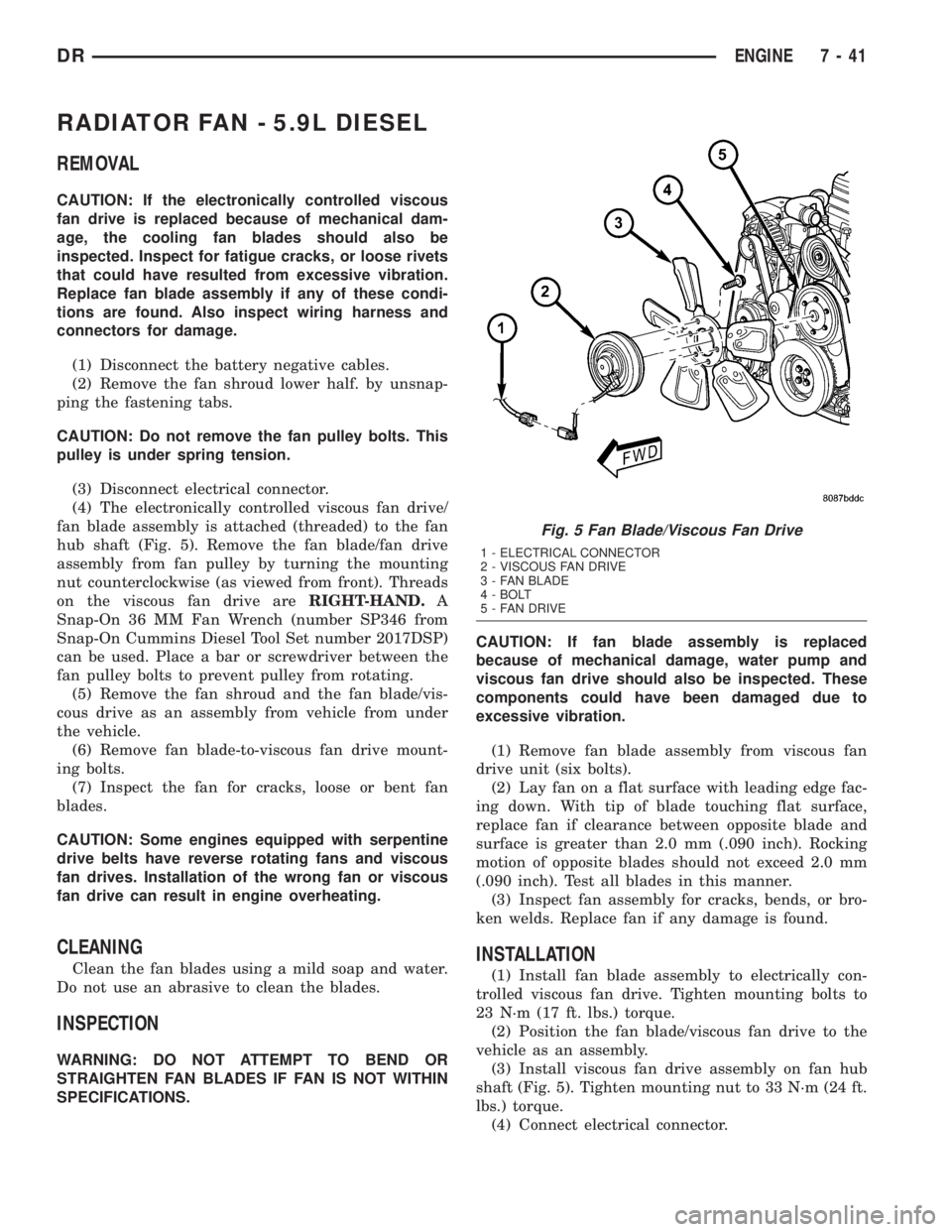
(4) The electronically controlled viscous fan drive/
fan blade assembly is attached (threaded) to the fan
hub shaft (Fig. 5). Remove the fan blade/fan drive
assembly from fan pulley by turning the mounting
nut counterclockwise (as viewed from front). Threads
on the viscous fan drive areRIGHT-HAND.A
Snap-On 36 MM Fan Wrench (number SP346 from
Snap-On Cummins Diesel Tool Set number 2017DSP)
can be used. Place a bar or screwdriver between the
fan pulley bolts to prevent pulley from rotating.
(5) Remove the fan shroud and the fan blade/vis-
cous drive as an assembly from vehicle from under
the vehicle.
(6) Remove fan blade-to-viscous fan drive mount-
ing bolts.
(7) Inspect the fan for cracks, loose or bent fan
blades.
CAUTION: Some engines equipped with serpentine
drive belts have reverse rotating fans and viscous
fan drives. Installation of the wrong fan or viscous
fan drive can result in engine overheating.
CLEANING
Clean the fan blades using a mild soap and water.
Do not use an abrasive to clean the blades.
INSPECTION
WARNING: DO NOT ATTEMPT TO BEND OR
STRAIGHTEN FAN BLADES IF FAN IS NOT WITHIN
SPECIFICATIONS.CAUTION: If fan blade assembly is replaced
because of mechanical damage, water pump and
viscous fan drive should also be inspected. These
components could have been damaged due to
excessive vibration.
(1) Remove fan blade assembly from viscous fan
drive unit (six bolts).
(2) Lay fan on a flat surface with leading edge fac-
ing down. With tip of blade touching flat surface,
replace fan if clearance between opposite blade and
surface is greater than 2.0 mm (.090 inch). Rocking
motion of opposite blades should not exceed 2.0 mm
(.090 inch). Test all blades in this manner.
(3) Inspect fan assembly for cracks, bends, or bro-
ken welds. Replace fan if any damage is found.
INSTALLATION
(1) Install fan blade assembly to electrically con-
trolled viscous fan drive. Tighten mounting bolts to
23 N´m (17 ft. lbs.) torque.
(2) Position the fan blade/viscous fan drive to the
vehicle as an assembly.
(3) Install viscous fan drive assembly on fan hub
shaft (Fig. 5). Tighten mounting nut to 33 N´m (24 ft.
lbs.) torque.
(4) Connect electrical connector.
Fig. 5 Fan Blade/Viscous Fan Drive
1 - ELECTRICAL CONNECTOR
2 - VISCOUS FAN DRIVE
3 - FAN BLADE
4 - BOLT
5 - FAN DRIVE
DRENGINE 7 - 41
Page 330 of 2895
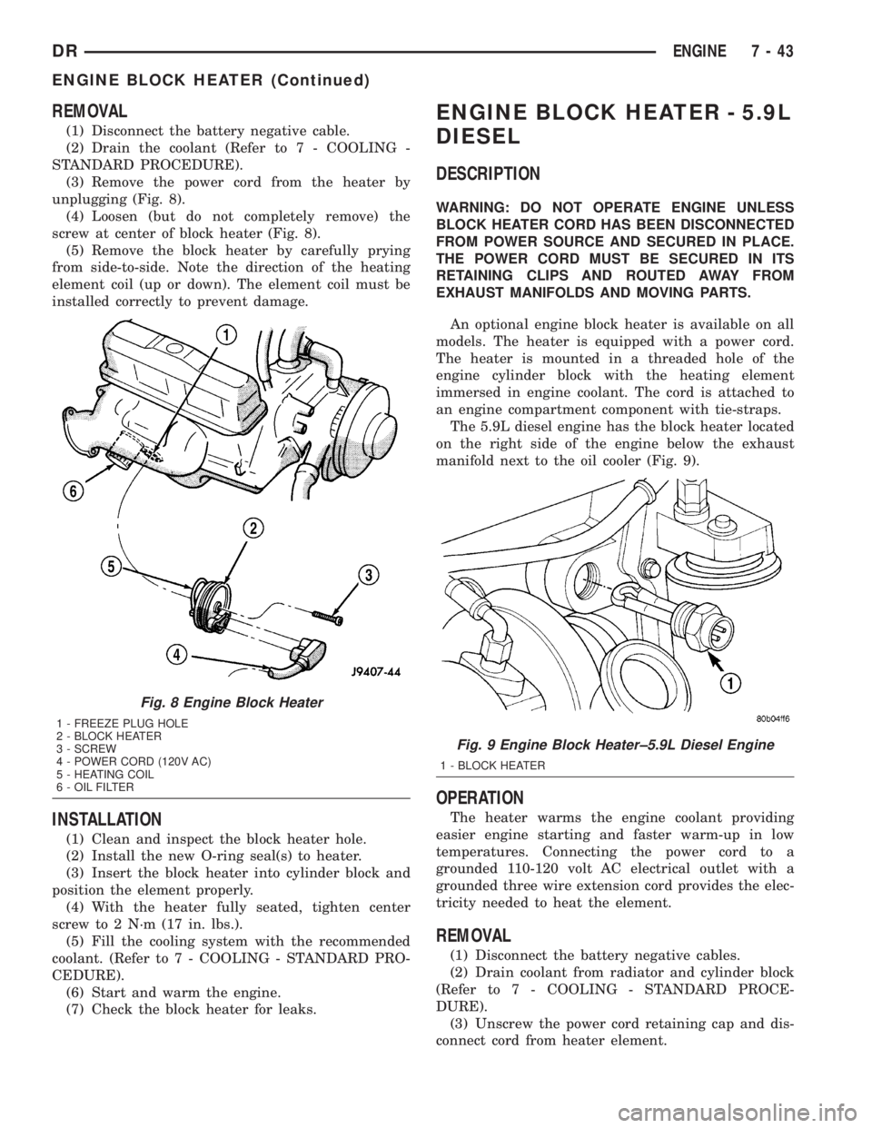
REMOVAL
(1) Disconnect the battery negative cable.
(2) Drain the coolant (Refer to 7 - COOLING -
STANDARD PROCEDURE).
(3) Remove the power cord from the heater by
unplugging (Fig. 8).
(4) Loosen (but do not completely remove) the
screw at center of block heater (Fig. 8).
(5) Remove the block heater by carefully prying
from side-to-side. Note the direction of the heating
element coil (up or down). The element coil must be
installed correctly to prevent damage.
INSTALLATION
(1) Clean and inspect the block heater hole.
(2) Install the new O-ring seal(s) to heater.
(3) Insert the block heater into cylinder block and
position the element properly.
(4) With the heater fully seated, tighten center
screw to 2 N´m (17 in. lbs.).
(5) Fill the cooling system with the recommended
coolant. (Refer to 7 - COOLING - STANDARD PRO-
CEDURE).
(6) Start and warm the engine.
(7) Check the block heater for leaks.
ENGINE BLOCK HEATER - 5.9L
DIESEL
DESCRIPTION
WARNING: DO NOT OPERATE ENGINE UNLESS
BLOCK HEATER CORD HAS BEEN DISCONNECTED
FROM POWER SOURCE AND SECURED IN PLACE.
THE POWER CORD MUST BE SECURED IN ITS
RETAINING CLIPS AND ROUTED AWAY FROM
EXHAUST MANIFOLDS AND MOVING PARTS.
An optional engine block heater is available on all
models. The heater is equipped with a power cord.
The heater is mounted in a threaded hole of the
engine cylinder block with the heating element
immersed in engine coolant. The cord is attached to
an engine compartment component with tie-straps.
The 5.9L diesel engine has the block heater located
on the right side of the engine below the exhaust
manifold next to the oil cooler (Fig. 9).
OPERATION
The heater warms the engine coolant providing
easier engine starting and faster warm-up in low
temperatures. Connecting the power cord to a
grounded 110-120 volt AC electrical outlet with a
grounded three wire extension cord provides the elec-
tricity needed to heat the element.
REMOVAL
(1) Disconnect the battery negative cables.
(2) Drain coolant from radiator and cylinder block
(Refer to 7 - COOLING - STANDARD PROCE-
DURE).
(3) Unscrew the power cord retaining cap and dis-
connect cord from heater element.
Fig. 8 Engine Block Heater
1 - FREEZE PLUG HOLE
2 - BLOCK HEATER
3 - SCREW
4 - POWER CORD (120V AC)
5 - HEATING COIL
6 - OIL FILTER
Fig. 9 Engine Block Heater±5.9L Diesel Engine
1 - BLOCK HEATER
DRENGINE 7 - 43
ENGINE BLOCK HEATER (Continued)