2003 DODGE RAM Oil pump
[x] Cancel search: Oil pumpPage 1502 of 2895
(8) To align the bearing cap, use cap slot, align-
ment dowel and cap bolts. DO NOT remove excess
material after assembly. DO NOT strike rear cap
more than 2 times for proper engagement.
(9) Clean and oil all cap bolts. Install all main
bearing caps. Install all cap bolts and alternately
tighten to 115 N´m (85 ft. lbs.) torque.
(10) Install oil pump (Refer to 9 - ENGINE/LU-
BRICATION/OIL PUMP - INSTALLATION).
(11) Install the timing chain cover (Refer to 9 -
ENGINE/VALVE TIMING/TIMING BELT / CHAIN
COVER(S) - INSTALLATION).
(12) Install the vibration damper (Refer to 9 -
ENGINE/ENGINE BLOCK/VIBRATION DAMPER -
INSTALLATION).
(13) Position the connecting rods onto the crank-
shaft and install the rod bearing caps. Tighten the
nuts to 61 N´m (45 ft. lbs.).
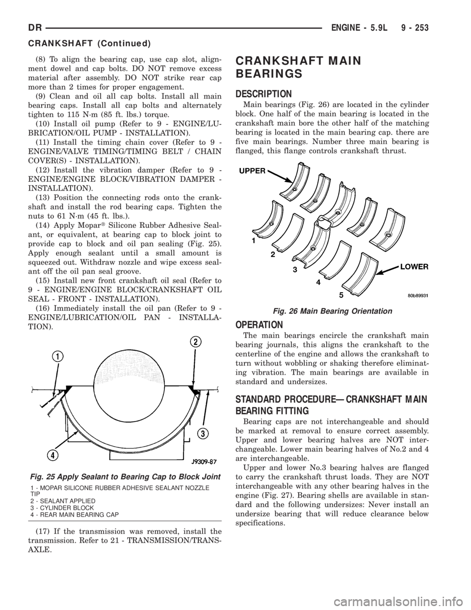
(14) Apply MopartSilicone Rubber Adhesive Seal-
ant, or equivalent, at bearing cap to block joint to
provide cap to block and oil pan sealing (Fig. 25).
Apply enough sealant until a small amount is
squeezed out. Withdraw nozzle and wipe excess seal-
ant off the oil pan seal groove.
(15) Install new front crankshaft oil seal (Refer to
9 - ENGINE/ENGINE BLOCK/CRANKSHAFT OIL
SEAL - FRONT - INSTALLATION).
(16) Immediately install the oil pan (Refer to 9 -
ENGINE/LUBRICATION/OIL PAN - INSTALLA-
TION).
(17) If the transmission was removed, install the
transmission. Refer to 21 - TRANSMISSION/TRANS-
AXLE.CRANKSHAFT MAIN
BEARINGS
DESCRIPTION
Main bearings (Fig. 26) are located in the cylinder
block. One half of the main bearing is located in the
crankshaft main bore the other half of the matching
bearing is located in the main bearing cap. there are
five main bearings. Number three main bearing is
flanged, this flange controls crankshaft thrust.
OPERATION
The main bearings encircle the crankshaft main
bearing journals, this aligns the crankshaft to the
centerline of the engine and allows the crankshaft to
turn without wobbling or shaking therefore eliminat-
ing vibration. The main bearings are available in
standard and undersizes.
STANDARD PROCEDUREÐCRANKSHAFT MAIN
BEARING FITTING
Bearing caps are not interchangeable and should
be marked at removal to ensure correct assembly.
Upper and lower bearing halves are NOT inter-
changeable. Lower main bearing halves of No.2 and 4
are interchangeable.
Upper and lower No.3 bearing halves are flanged
to carry the crankshaft thrust loads. They are NOT
interchangeable with any other bearing halves in the
engine (Fig. 27). Bearing shells are available in stan-
dard and the following undersizes: Never install an
undersize bearing that will reduce clearance below
specifications.
Fig. 25 Apply Sealant to Bearing Cap to Block Joint
1 - MOPAR SILICONE RUBBER ADHESIVE SEALANT NOZZLE
TIP
2 - SEALANT APPLIED
3 - CYLINDER BLOCK
4 - REAR MAIN BEARING CAP
Fig. 26 Main Bearing Orientation
DRENGINE - 5.9L 9 - 253
CRANKSHAFT (Continued)
Page 1503 of 2895
Main Bearing Undersize Availability List
²0.25 mm (0.001 inch)
²0.051 mm (0.002 inch)
²0.076 mm (0.003 inch)
²0.254 mm (0.010 inch)
²0.305 mm (0.012 inch)
REMOVAL
(1) Remove the oil pan (Refer to 9 - ENGINE/LU-
BRICATION/OIL PAN - REMOVAL).
(2) Remove the oil pump from the rear main bear-
ing cap (Refer to 9 - ENGINE/LUBRICATION/OIL
PUMP - REMOVAL).
(3) Identify bearing caps before removal. Remove
bearing caps one at a time.
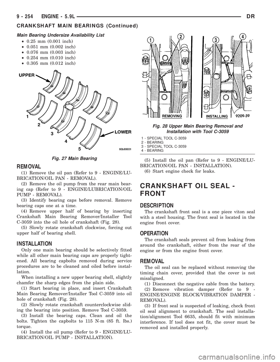
(4) Remove upper half of bearing by inserting
Crankshaft Main Bearing Remover/Installer Tool
C-3059 into the oil hole of crankshaft (Fig. 28).
(5) Slowly rotate crankshaft clockwise, forcing out
upper half of bearing shell.
INSTALLATION
Only one main bearing should be selectively fitted
while all other main bearing caps are properly tight-
ened. All bearing capbolts removed during service
procedures are to be cleaned and oiled before instal-
lation.
When installing a new upper bearing shell, slightly
chamfer the sharp edges from the plain side.
(1) Start bearing in place, and insert Crankshaft
Main Bearing Remover/Installer Tool C-3059 into oil
hole of crankshaft (Fig. 28).
(2) Slowly rotate crankshaft counterclockwise slid-
ing the bearing into position. Remove Tool C-3059.
(3) Install the bearing caps. Clean and oil the
bolts. Tighten the capbolts to 115 N´m (85 ft. lbs.)
torque.
(4) Install the oil pump (Refer to 9 - ENGINE/LU-
BRICATION/OIL PUMP - INSTALLATION).(5) Install the oil pan (Refer to 9 - ENGINE/LU-
BRICATION/OIL PAN - INSTALLATION).
(6) Start engine check for leaks.
CRANKSHAFT OIL SEAL -
FRONT
DESCRIPTION
The crankshaft front seal is a one piece viton seal
with a steel housing. The front seal is located in the
engine front cover.
OPERATION
The crankshaft seals prevent oil from leaking from
around the crankshaft, either from the rear of the
engine or from the engine front cover.
REMOVAL
The oil seal can be replaced without removing the
timing chain cover, provided that the cover is not
misaligned.
(1) Disconnect the negative cable from the battery.
(2) Remove vibration damper (Refer to 9 -
ENGINE/ENGINE BLOCK/VIBRATION DAMPER -
REMOVAL).
(3) If front seal is suspected of leaking, check front
oil seal alignment to crankshaft. The seal installa-
tion/alignment Tool 6635, should fit with minimum
interference. If tool does not fit, the cover must be
removed and installed properly.
Fig. 27 Main Bearing
Fig. 28 Upper Main Bearing Removal and
Installation with Tool C-3059
1 - SPECIAL TOOL C-3059
2 - BEARING
3 - SPECIAL TOOL C-3059
4 - BEARING
9 - 254 ENGINE - 5.9LDR
CRANKSHAFT MAIN BEARINGS (Continued)
Page 1505 of 2895
lower seal. The lower seal half can be installed only
with the rear main bearing cap removed.
UPPER SEAL ÐCRANKSHAFT REMOVED
(1) Remove the crankshaft (Refer to 9 - ENGINE/
ENGINE BLOCK/CRANKSHAFT - REMOVAL). Dis-
card the old upper seal.
UPPER SEALÐCRANKSHAFT INSTALLED
(1) Remove the oil pan (Refer to 9 - ENGINE/LU-
BRICATION/OIL PAN - REMOVAL).
(2) Remove the oil pump (Refer to 9 - ENGINE/
LUBRICATION/OIL PUMP - REMOVAL).
(3) Remove the rear main bearing cap. Remove
and discard the old lower oil seal.
(4) Carefully remove and discard the old upper oil
seal.
LOWER SEAL
(1) Remove the oil pan (Refer to 9 - ENGINE/LU-
BRICATION/OIL PAN - REMOVAL).
(2) Remove the oil pump (Refer to 9 - ENGINE/
LUBRICATION/OIL PUMP - REMOVAL).
(3) Remove the rear main bearing cap and discard
the old lower seal.
INSTALLATION
The service seal is a two piece, Viton seal. The
upper seal half can be installed with crankshaft
removed from engine or with crankshaft installed.
When a new upper seal is installed, install a new
lower seal. The lower seal half can be installed only
with the rear main bearing cap removed.
UPPER SEAL ÐCRANKSHAFT REMOVED
(1) Clean the cylinder block rear cap mating sur-
face. Be sure the seal groove is free of debris. Check
for burrs at the oil hole on the cylinder block mating
surface to rear cap.
(2) Lightly oil the new upper seal lips with engine
oil.
(3) Install the new upper rear bearing oil seal with
the white paint facing toward the rear of the engine.
(4) Position the crankshaft into the cylinder block.
(5)
Lightly oil the new lower seal lips with engine oil.
(6) Install the new lower rear bearing oil seal into
the bearing cap with the white paint facing towards
the rear of the engine.
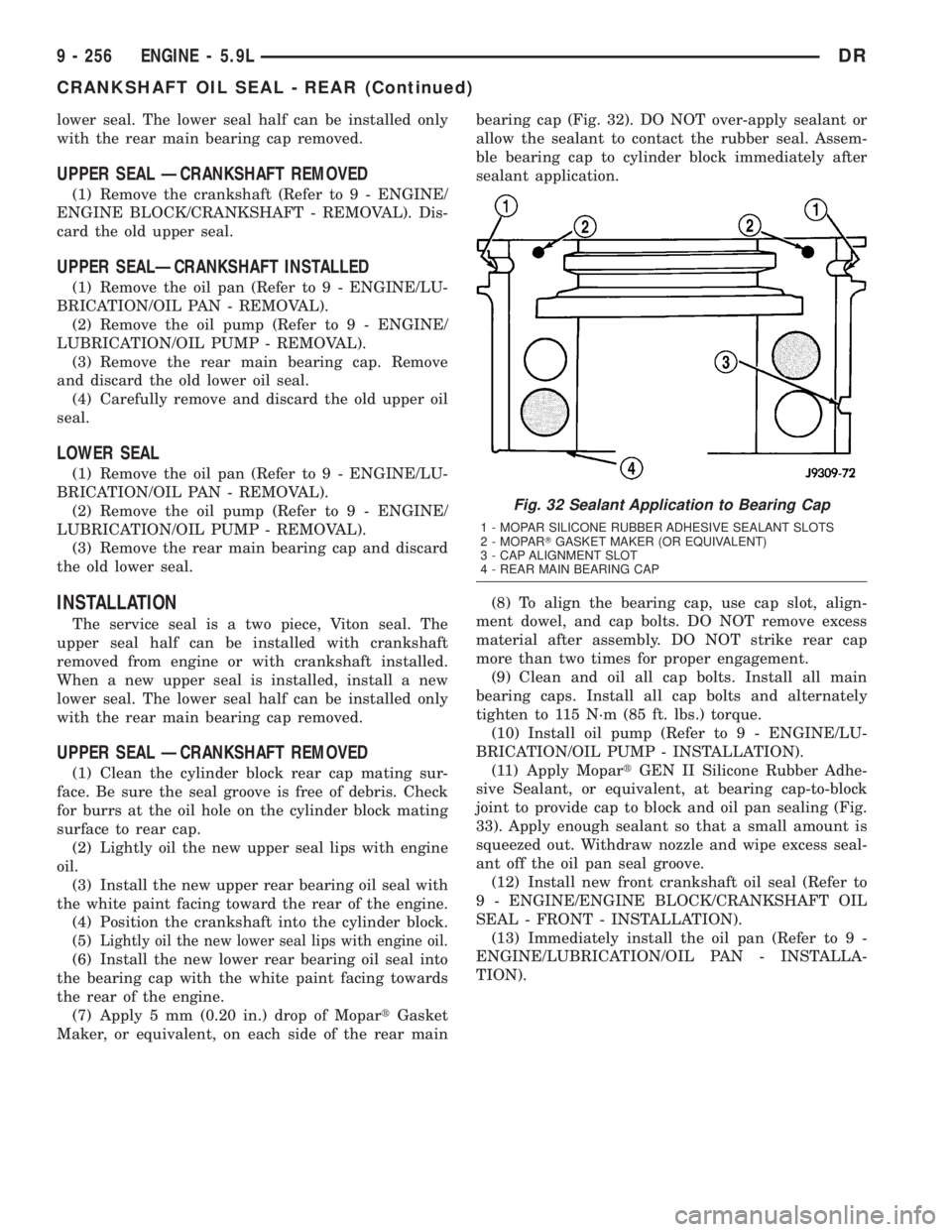
(7) Apply 5 mm (0.20 in.) drop of MopartGasket
Maker, or equivalent, on each side of the rear mainbearing cap (Fig. 32). DO NOT over-apply sealant or
allow the sealant to contact the rubber seal. Assem-
ble bearing cap to cylinder block immediately after
sealant application.
(8) To align the bearing cap, use cap slot, align-
ment dowel, and cap bolts. DO NOT remove excess
material after assembly. DO NOT strike rear cap
more than two times for proper engagement.
(9) Clean and oil all cap bolts. Install all main
bearing caps. Install all cap bolts and alternately
tighten to 115 N´m (85 ft. lbs.) torque.
(10) Install oil pump (Refer to 9 - ENGINE/LU-
BRICATION/OIL PUMP - INSTALLATION).
(11) Apply MopartGEN II Silicone Rubber Adhe-
sive Sealant, or equivalent, at bearing cap-to-block
joint to provide cap to block and oil pan sealing (Fig.
33). Apply enough sealant so that a small amount is
squeezed out. Withdraw nozzle and wipe excess seal-
ant off the oil pan seal groove.
(12) Install new front crankshaft oil seal (Refer to
9 - ENGINE/ENGINE BLOCK/CRANKSHAFT OIL
SEAL - FRONT - INSTALLATION).
(13) Immediately install the oil pan (Refer to 9 -
ENGINE/LUBRICATION/OIL PAN - INSTALLA-
TION).
Fig. 32 Sealant Application to Bearing Cap
1 - MOPAR SILICONE RUBBER ADHESIVE SEALANT SLOTS
2 - MOPARTGASKET MAKER (OR EQUIVALENT)
3 - CAP ALIGNMENT SLOT
4 - REAR MAIN BEARING CAP
9 - 256 ENGINE - 5.9LDR
CRANKSHAFT OIL SEAL - REAR (Continued)
Page 1506 of 2895
UPPER SEALÐCRANKSHAFT INSTALLED
(1) Clean the cylinder block mating surfaces before
oil seal installation. Check for burrs at the oil hole on
the cylinder block mating surface to rear cap.
(2) Lightly oil the new upper seal lips with engine
oil. To allow ease of installation of the seal, loosen at
least the two main bearing caps forward of the rear
bearing cap.
(3) Rotate the new upper seal into the cylinder
block, being careful not to shave or cut the outer sur-
face of the seal. To ensure proper installation, use the
installation tool provided with the kit. Install the
new seal with the white paint facing toward the rear
of the engine.
(4) Install the new lower rear bearing oil seal into
the bearing cap with the white paint facing toward
the rear of the engine.
(5) Apply 5 mm (0.20 in.) drop of MopartGasket
Maker, or equivalent, on each side of the rear main
bearing cap (Fig. 32). DO NOT over-apply sealant or
allow the sealant to contact the rubber seal. Assem-
ble bearing cap to cylinder block immediately after
sealant application. Be sure the white paint faces
toward the rear of the engine.
(6) To align the bearing cap, use cap slot, align-
ment dowel, and cap bolts. DO NOT remove excess
material after assembly. DO NOT strike rear cap
more than two times for proper engagement.(7) Install the rear main bearing cap with cleaned
and oiled cap bolts. Alternately tighten ALL cap bolts
to 115 N´m (85 ft. lbs.) torque.
(8) Install oil pump (Refer to 9 - ENGINE/LUBRI-
CATION/OIL PUMP - INSTALLATION).
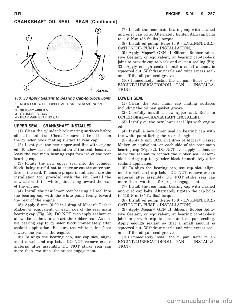
(9) Apply MopartGEN II Silicone Rubber Adhe-
sive Sealant, or equivalent, at bearing cap-to-block
joint to provide cap-to-block and oil pan sealing (Fig.
33). Apply enough sealant until a small amount is
squeezed out. Withdraw nozzle and wipe excess seal-
ant off the oil pan seal groove.
(10) Immediately install the oil pan (Refer to 9 -
ENGINE/LUBRICATION/OIL PAN - INSTALLA-
TION).
LOWER SEAL
(1) Clean the rear main cap mating surfaces
including the oil pan gasket groove.
(2) Carefully install a new upper seal. Refer to
UPPER SEALÐCRANKSHAFT INSTALLED.
(3) Lightly oil the new lower seal lips with engine
oil.
(4) Install a new lower seal in bearing cap with
the white paint facing the rear of engine.
(5) Apply 5 mm (0.20 in.) drop of MopartGasket
Maker, or equivalent, on each side of the rear main
bearing cap (Fig. 32). DO NOT over-apply sealant or
allow the sealant to contact the rubber seal. Assem-
ble bearing cap to cylinder block immediately after
sealant application.
(6) To align the bearing cap, use cap slot, align-
ment dowel, and cap bolts. DO NOT remove excess
material after assembly. DO NOT strike rear cap
more than two times for proper engagement.
(7) Install the rear main bearing cap with cleaned
and oiled cap bolts. Alternately tighten the cap bolts
to 115 N´m (85 ft. lbs.) torque.
(8) Install oil pump (Refer to 9 - ENGINE/LUBRI-
CATION/OIL PUMP - INSTALLATION).
(9) Apply MopartGEN II Silicone Rubber Adhe-
sive Sealant, or equivalent, at bearing cap-to-block
joint to provide cap to block and oil pan sealing.
Apply enough sealant so that a small amount is
squeezed out. Withdraw nozzle and wipe excess seal-
ant off the oil pan seal groove.
(10) Immediately install the oil pan (Refer to 9 -
ENGINE/LUBRICATION/OIL PAN - INSTALLA-
TION).
Fig. 33 Apply Sealant to Bearing Cap-to-Block Joint
1 - MOPAR SILICONE RUBBER ADHESIVE SEALANT NOZZLE
TIP
2 - SEALANT APPLIED
3 - CYLINDER BLOCK
4 - REAR MAIN BEARING CAP
DRENGINE - 5.9L 9 - 257
CRANKSHAFT OIL SEAL - REAR (Continued)
Page 1507 of 2895
DISTRIBUTOR BUSHING
REMOVAL
(1) Remove distributor (Refer to 8 - ELECTRICAL/
IGNITION CONTROL/DISTRIBUTOR - REMOVAL).
(2) Remove the intake manifold (Refer to 9 -
ENGINE/MANIFOLDS/INTAKE MANIFOLD -
REMOVAL).
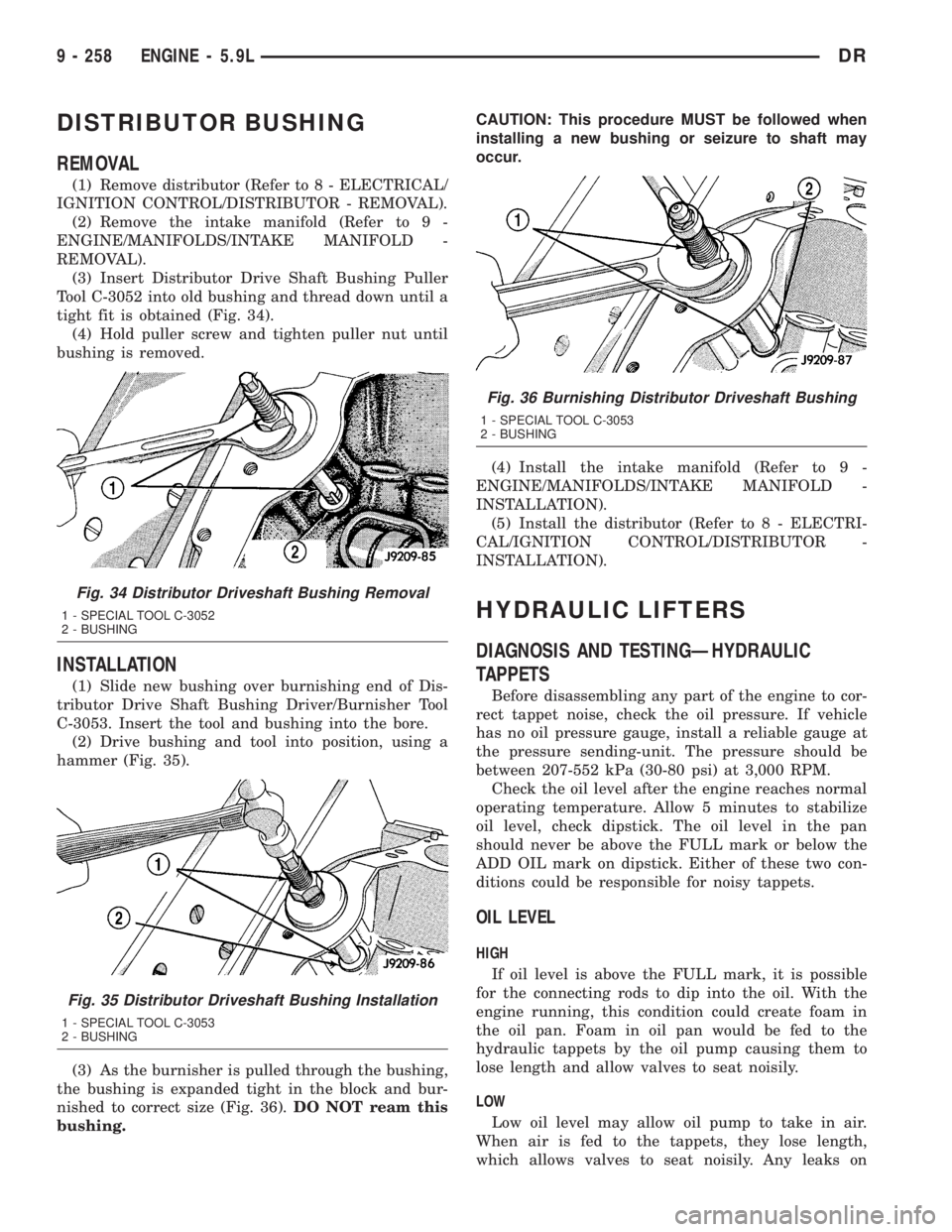
(3) Insert Distributor Drive Shaft Bushing Puller
Tool C-3052 into old bushing and thread down until a
tight fit is obtained (Fig. 34).
(4) Hold puller screw and tighten puller nut until
bushing is removed.
INSTALLATION
(1) Slide new bushing over burnishing end of Dis-
tributor Drive Shaft Bushing Driver/Burnisher Tool
C-3053. Insert the tool and bushing into the bore.
(2) Drive bushing and tool into position, using a
hammer (Fig. 35).
(3) As the burnisher is pulled through the bushing,
the bushing is expanded tight in the block and bur-
nished to correct size (Fig. 36).DO NOT ream this
bushing.CAUTION: This procedure MUST be followed when
installing a new bushing or seizure to shaft may
occur.
(4) Install the intake manifold (Refer to 9 -
ENGINE/MANIFOLDS/INTAKE MANIFOLD -
INSTALLATION).
(5) Install the distributor (Refer to 8 - ELECTRI-
CAL/IGNITION CONTROL/DISTRIBUTOR -
INSTALLATION).
HYDRAULIC LIFTERS
DIAGNOSIS AND TESTINGÐHYDRAULIC
TAPPETS
Before disassembling any part of the engine to cor-
rect tappet noise, check the oil pressure. If vehicle
has no oil pressure gauge, install a reliable gauge at
the pressure sending-unit. The pressure should be
between 207-552 kPa (30-80 psi) at 3,000 RPM.
Check the oil level after the engine reaches normal
operating temperature. Allow 5 minutes to stabilize
oil level, check dipstick. The oil level in the pan
should never be above the FULL mark or below the
ADD OIL mark on dipstick. Either of these two con-
ditions could be responsible for noisy tappets.
OIL LEVEL
HIGH
If oil level is above the FULL mark, it is possible
for the connecting rods to dip into the oil. With the
engine running, this condition could create foam in
the oil pan. Foam in oil pan would be fed to the
hydraulic tappets by the oil pump causing them to
lose length and allow valves to seat noisily.
LOW
Low oil level may allow oil pump to take in air.
When air is fed to the tappets, they lose length,
which allows valves to seat noisily. Any leaks on
Fig. 34 Distributor Driveshaft Bushing Removal
1 - SPECIAL TOOL C-3052
2 - BUSHING
Fig. 35 Distributor Driveshaft Bushing Installation
1 - SPECIAL TOOL C-3053
2 - BUSHING
Fig. 36 Burnishing Distributor Driveshaft Bushing
1 - SPECIAL TOOL C-3053
2 - BUSHING
9 - 258 ENGINE - 5.9LDR
Page 1508 of 2895
intake side of oil pump through which air can be
drawn will create the same tappet action. Check the
lubrication system from the intake strainer to the
pump cover, including the relief valve retainer cap.
When tappet noise is due to aeration, it may be
intermittent or constant, and usually more than one
tappet will be noisy. When oil level and leaks have
been corrected, operate the engine at fast idle. Run
engine for a sufficient time to allow all of the air
inside the tappets to be bled out.
TAPPET NOISE DIAGNOSIS
(1) To determine source of tappet noise, operate
engine at idle with cylinder head covers removed.
(2) Feel each valve spring or rocker arm to detect
noisy tappet. The noisy tappet will cause the affected
spring and/or rocker arm to vibrate or feel rough in
operation.
NOTE: Worn valve guides or cocked springs are
sometimes mistaken for noisy tappets. If such is
the case, noise may be dampened by applying side
thrust on the valve spring. If noise is not apprecia-
bly reduced, it can be assumed the noise is in the
tappet. Inspect the rocker arm push rod sockets
and push rod ends for wear.
(3) Valve tappet noise ranges from light noise to a
heavy click. A light noise is usually caused by exces-
sive leak-down around the unit plunger, or by the
plunger partially sticking in the tappet body cylinder.
The tappet should be replaced. A heavy click is
caused by a tappet check valve not seating, or by for-
eign particles wedged between the plunger and the
tappet body. This will cause the plunger to stick in
the down position. This heavy click will be accompa-
nied by excessive clearance between the valve stem
and rocker arm as valve closes. In either case, tappet
assembly should be removed for inspection and clean-
ing.
(4) The valve train generates a noise very much
like a light tappet noise during normal operation.
Care must be taken to ensure that tappets are mak-
ing the noise. If more than one tappet seems to be
noisy, it's probably not the tappets.
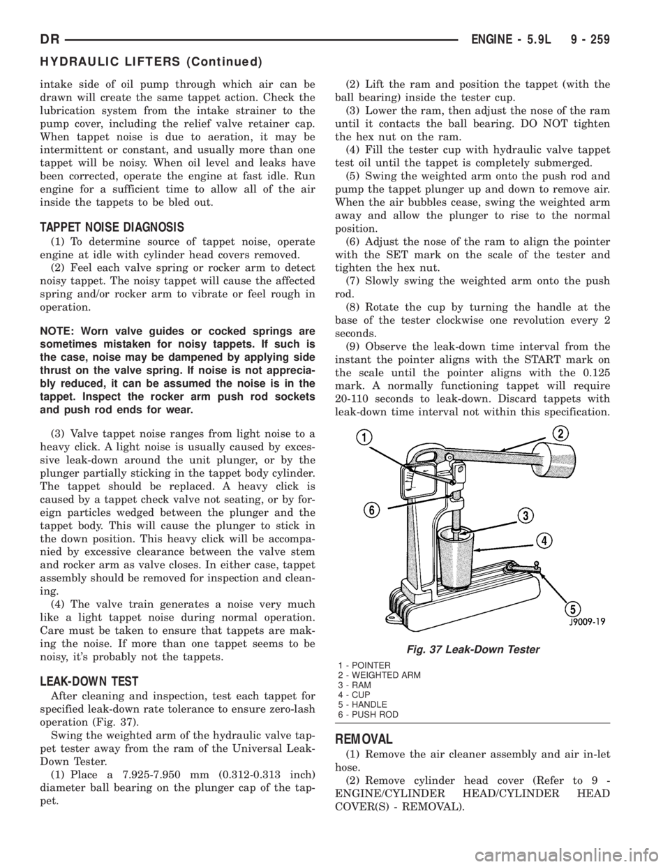
LEAK-DOWN TEST
After cleaning and inspection, test each tappet for
specified leak-down rate tolerance to ensure zero-lash
operation (Fig. 37).
Swing the weighted arm of the hydraulic valve tap-
pet tester away from the ram of the Universal Leak-
Down Tester.
(1) Place a 7.925-7.950 mm (0.312-0.313 inch)
diameter ball bearing on the plunger cap of the tap-
pet.(2) Lift the ram and position the tappet (with the
ball bearing) inside the tester cup.
(3) Lower the ram, then adjust the nose of the ram
until it contacts the ball bearing. DO NOT tighten
the hex nut on the ram.
(4) Fill the tester cup with hydraulic valve tappet
test oil until the tappet is completely submerged.
(5) Swing the weighted arm onto the push rod and
pump the tappet plunger up and down to remove air.
When the air bubbles cease, swing the weighted arm
away and allow the plunger to rise to the normal
position.
(6) Adjust the nose of the ram to align the pointer
with the SET mark on the scale of the tester and
tighten the hex nut.
(7) Slowly swing the weighted arm onto the push
rod.
(8) Rotate the cup by turning the handle at the
base of the tester clockwise one revolution every 2
seconds.
(9) Observe the leak-down time interval from the
instant the pointer aligns with the START mark on
the scale until the pointer aligns with the 0.125
mark. A normally functioning tappet will require
20-110 seconds to leak-down. Discard tappets with
leak-down time interval not within this specification.
REMOVAL
(1) Remove the air cleaner assembly and air in-let
hose.
(2) Remove cylinder head cover (Refer to 9 -
ENGINE/CYLINDER HEAD/CYLINDER HEAD
COVER(S) - REMOVAL).
Fig. 37 Leak-Down Tester
1 - POINTER
2 - WEIGHTED ARM
3 - RAM
4 - CUP
5 - HANDLE
6 - PUSH ROD
DRENGINE - 5.9L 9 - 259
HYDRAULIC LIFTERS (Continued)
Page 1516 of 2895
(5) Raise the transmission enough to remove the
mount from the crossmember.
(6) Remove the mount.
INSTALLATION
NOTE: Threadlocking compound must be applied to
the bolts before installation.
(1) Install the two bolts that attach the transmis-
sion mount to the transmission bracket.
(2) Torque the bolts to 61N´m (45 ft.lbs.) torque.
(3) Lower the transmission so the transmission
mount rests on the crossmember, and the studs of
the transmission mount are aligned in the slots in
the crossmember.
(4) Install the nuts onto the transmission mount
studs through the crossmember access slot.
(5) Torque the nuts to 54N´m (40 ft. lbs.).
LUBRICATION
DESCRIPTION
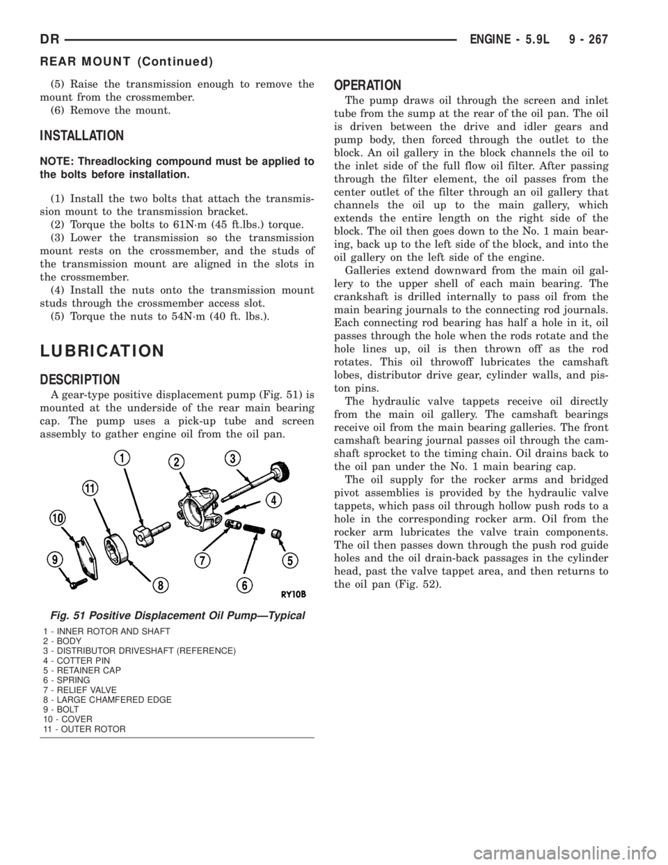
A gear-type positive displacement pump (Fig. 51) is
mounted at the underside of the rear main bearing
cap. The pump uses a pick-up tube and screen
assembly to gather engine oil from the oil pan.
OPERATION
The pump draws oil through the screen and inlet
tube from the sump at the rear of the oil pan. The oil
is driven between the drive and idler gears and
pump body, then forced through the outlet to the
block. An oil gallery in the block channels the oil to
the inlet side of the full flow oil filter. After passing
through the filter element, the oil passes from the
center outlet of the filter through an oil gallery that
channels the oil up to the main gallery, which
extends the entire length on the right side of the
block. The oil then goes down to the No. 1 main bear-
ing, back up to the left side of the block, and into the
oil gallery on the left side of the engine.
Galleries extend downward from the main oil gal-
lery to the upper shell of each main bearing. The
crankshaft is drilled internally to pass oil from the
main bearing journals to the connecting rod journals.
Each connecting rod bearing has half a hole in it, oil
passes through the hole when the rods rotate and the
hole lines up, oil is then thrown off as the rod
rotates. This oil throwoff lubricates the camshaft
lobes, distributor drive gear, cylinder walls, and pis-
ton pins.
The hydraulic valve tappets receive oil directly
from the main oil gallery. The camshaft bearings
receive oil from the main bearing galleries. The front
camshaft bearing journal passes oil through the cam-
shaft sprocket to the timing chain. Oil drains back to
the oil pan under the No. 1 main bearing cap.
The oil supply for the rocker arms and bridged
pivot assemblies is provided by the hydraulic valve
tappets, which pass oil through hollow push rods to a
hole in the corresponding rocker arm. Oil from the
rocker arm lubricates the valve train components.
The oil then passes down through the push rod guide
holes and the oil drain-back passages in the cylinder
head, past the valve tappet area, and then returns to
the oil pan (Fig. 52).
Fig. 51 Positive Displacement Oil PumpÐTypical
1 - INNER ROTOR AND SHAFT
2 - BODY
3 - DISTRIBUTOR DRIVESHAFT (REFERENCE)
4 - COTTER PIN
5 - RETAINER CAP
6 - SPRING
7 - RELIEF VALVE
8 - LARGE CHAMFERED EDGE
9 - BOLT
10 - COVER
11 - OUTER ROTOR
DRENGINE - 5.9L 9 - 267
REAR MOUNT (Continued)
Page 1517 of 2895
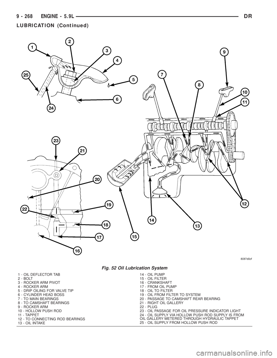
Fig. 52 Oil Lubrication System
1 - OIL DEFLECTOR TAB
2 - BOLT
3 - ROCKER ARM PIVOT
4 - ROCKER ARM
5 - DRIP OILING FOR VALVE TIP
6 - CYLINDER HEAD BOSS
7 - TO MAIN BEARINGS
8 - TO CAMSHAFT BEARINGS
9 - ROCKER ARM
10 - HOLLOW PUSH ROD
11 - TAPPET
12 - TO CONNECTING ROD BEARINGS
13 - OIL INTAKE14 - OIL PUMP
15 - OIL FILTER
16 - CRANKSHAFT
17 - FROM OIL PUMP
18 - OIL TO FILTER
19 - OIL FROM FILTER TO SYSTEM
20 - PASSAGE TO CAMSHAFT REAR BEARING
21 - RIGHT OIL GALLERY
22 - PLUG
23 - OIL PASSAGE FOR OIL PRESSURE INDICATOR LIGHT
24 - OIL SUPPLY VIA HOLLOW PUSH ROD SUPPLY IS FROM
OIL GALLERY METERED THROUGH HYDRAULIC TAPPET
25 - OIL SUPPLY FROM HOLLOW PUSH ROD
9 - 268 ENGINE - 5.9LDR
LUBRICATION (Continued)