2003 DODGE RAM Oil pump
[x] Cancel search: Oil pumpPage 1440 of 2895
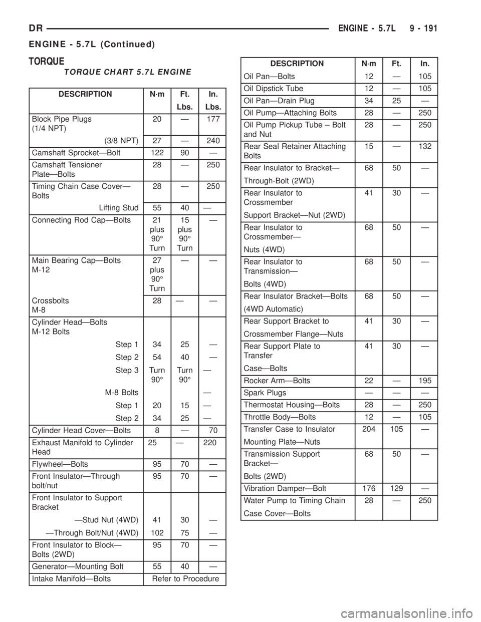
TORQUE
TORQUE CHART 5.7L ENGINE
DESCRIPTION N´m Ft. In.
Lbs. Lbs.
Block Pipe Plugs
(1/4 NPT)20 Ð 177
(3/8 NPT) 27 Ð 240
Camshaft SprocketÐBolt 122 90 Ð
Camshaft Tensioner
PlateÐBolts28 Ð 250
Timing Chain Case CoverÐ
Bolts28 Ð 250
Lifting Stud 55 40 Ð
Connecting Rod CapÐBolts 21
plus
90É
Turn15
plus
90É
TurnÐ
Main Bearing CapÐBolts
M-1227
plus
90É
TurnÐÐ
Crossbolts
M-828 Ð Ð
Cylinder HeadÐBolts
M-12 Bolts
Step 1 34 25 Ð
Step 2 54 40 Ð
Step 3 Turn
90ÉTurn
90ÉÐ
M-8 Bolts Ð
Step 1 20 15 Ð
Step 2 34 25 Ð
Cylinder Head CoverÐBolts 8 Ð 70
Exhaust Manifold to Cylinder
Head25 Ð 220
FlywheelÐBolts 95 70 Ð
Front InsulatorÐThrough
bolt/nut95 70 Ð
Front Insulator to Support
Bracket
ÐStud Nut (4WD) 41 30 Ð
ÐThrough Bolt/Nut (4WD) 102 75 Ð
Front Insulator to BlockÐ
Bolts (2WD)95 70 Ð
GeneratorÐMounting Bolt 55 40 Ð
Intake ManifoldÐBolts Refer to Procedure
DESCRIPTION N´m Ft. In.
Oil PanÐBolts 12 Ð 105
Oil Dipstick Tube 12 Ð 105
Oil PanÐDrain Plug 34 25 Ð
Oil PumpÐAttaching Bolts 28 Ð 250
Oil Pump Pickup Tube ± Bolt
and Nut28 Ð 250
Rear Seal Retainer Attaching
Bolts15 Ð 132
Rear Insulator to BracketÐ 68 50 Ð
Through-Bolt (2WD)
Rear Insulator to
Crossmember41 30 Ð
Support BracketÐNut (2WD)
Rear Insulator to
CrossmemberÐ68 50 Ð
Nuts (4WD)
Rear Insulator to
TransmissionÐ68 50 Ð
Bolts (4WD)
Rear Insulator BracketÐBolts 68 50 Ð
(4WD Automatic)
Rear Support Bracket to 41 30 Ð
Crossmember FlangeÐNuts
Rear Support Plate to
Transfer41 30 Ð
CaseÐBolts
Rocker ArmÐBolts 22 Ð 195
Spark Plugs Ð Ð Ð
Thermostat HousingÐBolts 28 Ð 250
Throttle BodyÐBolts 12 Ð 105
Transfer Case to Insulator 204 105 Ð
Mounting PlateÐNuts
Transmission Support
BracketÐ68 50 Ð
Bolts (2WD)
Vibration DamperÐBolt 176 129 Ð
Water Pump to Timing Chain 28 Ð 250
Case CoverÐBolts
DRENGINE - 5.7L 9 - 191
ENGINE - 5.7L (Continued)
Page 1450 of 2895
(14) Remove the oil pump(Refer to 9 - ENGINE/
LUBRICATION/OIL PUMP - REMOVAL).
(15) Remove timing chain(Refer to 9 - ENGINE/
VALVE TIMING/TIMING BELT/CHAIN AND
SPROCKETS - REMOVAL).
(16) Remove camshaft tensioner/thrust plate
assembly.
NOTE: Identify lifters to ensure installation in origi-
nal location.
(17) Remove the lifters and retainer assembly.
(18) Install a long bolt into front of camshaft to aid
in removal of the camshaft. Remove camshaft, being
careful not to damage cam bearings with the cam
lobes.
INSPECTION
(1) The cam bearings are not serviceable. Do not
attempt to replace cam bearings for any reason.
INSTALLATION
INSTALLATION - CAMSHAFT CORE HOLE PLUG
CAUTION: The new core hole plug must be installed
to the proper depth or camshaft damage could
develope. The plug must be installed squarely in
the bore.
(1) Install a new core hole plug at the rear of cam-
shaft, using special tool # 9048. Clean plug and apply
mopartlock and seal adhesive to the edge of the
plug, before installing. The plug must be installed to
a depth of+/-0.25mm from the end of the machined
bevel, that is the end of the bevel that is closest to
the cam bearing.
INSTALLATION - CAMSHAFT
(1) Lubricate camshaft lobes and camshaft bearing
journals and insert the camshaft
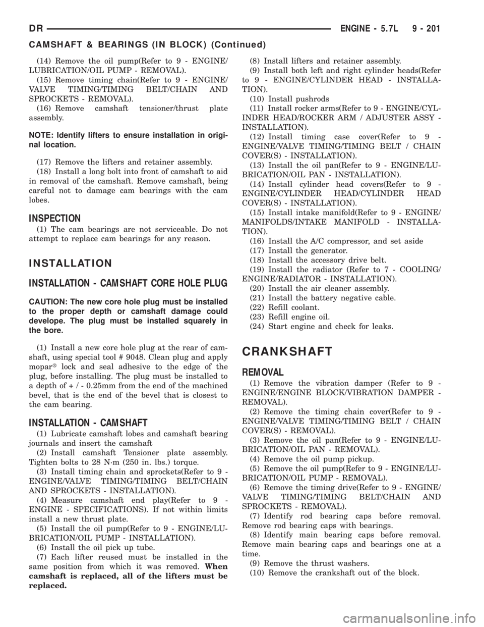
(2) Install camshaft Tensioner plate assembly.
Tighten bolts to 28 N´m (250 in. lbs.) torque.
(3) Install timing chain and sprockets(Refer to 9 -
ENGINE/VALVE TIMING/TIMING BELT/CHAIN
AND SPROCKETS - INSTALLATION).
(4) Measure camshaft end play(Refer to 9 -
ENGINE - SPECIFICATIONS). If not within limits
install a new thrust plate.
(5) Install the oil pump(Refer to 9 - ENGINE/LU-
BRICATION/OIL PUMP - INSTALLATION).
(6) Install the oil pick up tube.
(7) Each lifter reused must be installed in the
same position from which it was removed.When
camshaft is replaced, all of the lifters must be
replaced.(8) Install lifters and retainer assembly.
(9) Install both left and right cylinder heads(Refer
to 9 - ENGINE/CYLINDER HEAD - INSTALLA-
TION).
(10) Install pushrods
(11) Install rocker arms(Refer to 9 - ENGINE/CYL-
INDER HEAD/ROCKER ARM / ADJUSTER ASSY -
INSTALLATION).
(12) Install timing case cover(Refer to 9 -
ENGINE/VALVE TIMING/TIMING BELT / CHAIN
COVER(S) - INSTALLATION).
(13) Install the oil pan(Refer to 9 - ENGINE/LU-
BRICATION/OIL PAN - INSTALLATION).
(14) Install cylinder head covers(Refer to 9 -
ENGINE/CYLINDER HEAD/CYLINDER HEAD
COVER(S) - INSTALLATION).
(15) Install intake manifold(Refer to 9 - ENGINE/
MANIFOLDS/INTAKE MANIFOLD - INSTALLA-
TION).
(16) Install the A/C compressor, and set aside
(17) Install the generator.
(18) Install the accessory drive belt.
(19) Install the radiator (Refer to 7 - COOLING/
ENGINE/RADIATOR - INSTALLATION).
(20) Install the air cleaner assembly.
(21) Install the battery negative cable.
(22) Refill coolant.
(23) Refill engine oil.
(24) Start engine and check for leaks.
CRANKSHAFT
REMOVAL
(1) Remove the vibration damper (Refer to 9 -
ENGINE/ENGINE BLOCK/VIBRATION DAMPER -
REMOVAL).
(2) Remove the timing chain cover(Refer to 9 -
ENGINE/VALVE TIMING/TIMING BELT / CHAIN
COVER(S) - REMOVAL).
(3) Remove the oil pan(Refer to 9 - ENGINE/LU-
BRICATION/OIL PAN - REMOVAL).
(4) Remove the oil pump pickup.
(5) Remove the oil pump(Refer to 9 - ENGINE/LU-
BRICATION/OIL PUMP - REMOVAL).
(6) Remove the timing drive(Refer to 9 - ENGINE/
VALVE TIMING/TIMING BELT/CHAIN AND
SPROCKETS - REMOVAL).
(7) Identify rod bearing caps before removal.
Remove rod bearing caps with bearings.
(8) Identify main bearing caps before removal.
Remove main bearing caps and bearings one at a
time.
(9) Remove the thrust washers.
(10) Remove the crankshaft out of the block.
DRENGINE - 5.7L 9 - 201
CAMSHAFT & BEARINGS (IN BLOCK) (Continued)
Page 1451 of 2895
(11) Remove the rear oil seal retainer(Refer to 9 -
ENGINE/ENGINE BLOCK/CRANKSHAFT REAR
OIL SEAL RETAINE - REMOVAL).
(12) Remove and discard the crankshaft rear oil
seal.
(13) Remove and discard the front crankshaft oil
seal.
INSTALLATION
(1) Select the proper main bearings(Refer to 9 -
ENGINE/ENGINE BLOCK/CRANKSHAFT MAIN
BEARINGS - STANDARD PROCEDURE).
(2) Install main bearings in block and caps, and
lubricate bearings.
(3) Position the crankshaft into the cylinder block.
(4) Install the thrust washers.
NOTE: The main cap crossbolts are torqued after
final torque of the main cap bolts. Always use a
new washer/seal on crossbolts.
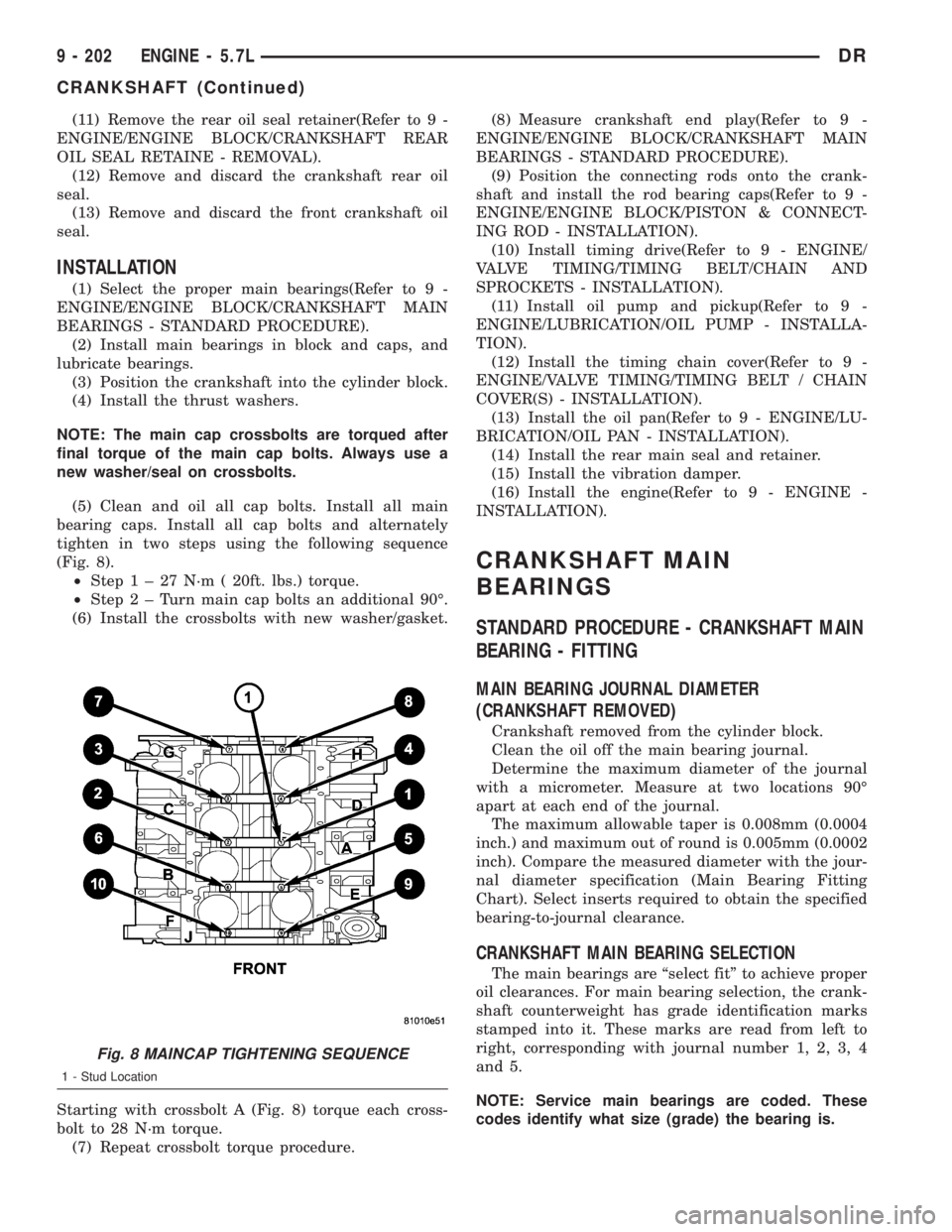
(5) Clean and oil all cap bolts. Install all main
bearing caps. Install all cap bolts and alternately
tighten in two steps using the following sequence
(Fig. 8).
²Step1±27N´m(20ft. lbs.) torque.
²Step2±Turnmain cap bolts an additional 90É.
(6) Install the crossbolts with new washer/gasket.
Starting with crossbolt A (Fig. 8) torque each cross-
bolt to 28 N´m torque.
(7) Repeat crossbolt torque procedure.(8) Measure crankshaft end play(Refer to 9 -
ENGINE/ENGINE BLOCK/CRANKSHAFT MAIN
BEARINGS - STANDARD PROCEDURE).
(9) Position the connecting rods onto the crank-
shaft and install the rod bearing caps(Refer to 9 -
ENGINE/ENGINE BLOCK/PISTON & CONNECT-
ING ROD - INSTALLATION).
(10) Install timing drive(Refer to 9 - ENGINE/
VALVE TIMING/TIMING BELT/CHAIN AND
SPROCKETS - INSTALLATION).
(11) Install oil pump and pickup(Refer to 9 -
ENGINE/LUBRICATION/OIL PUMP - INSTALLA-
TION).
(12) Install the timing chain cover(Refer to 9 -
ENGINE/VALVE TIMING/TIMING BELT / CHAIN
COVER(S) - INSTALLATION).
(13) Install the oil pan(Refer to 9 - ENGINE/LU-
BRICATION/OIL PAN - INSTALLATION).
(14) Install the rear main seal and retainer.
(15) Install the vibration damper.
(16) Install the engine(Refer to 9 - ENGINE -
INSTALLATION).
CRANKSHAFT MAIN
BEARINGS
STANDARD PROCEDURE - CRANKSHAFT MAIN
BEARING - FITTING
MAIN BEARING JOURNAL DIAMETER
(CRANKSHAFT REMOVED)
Crankshaft removed from the cylinder block.
Clean the oil off the main bearing journal.
Determine the maximum diameter of the journal
with a micrometer. Measure at two locations 90É
apart at each end of the journal.
The maximum allowable taper is 0.008mm (0.0004
inch.) and maximum out of round is 0.005mm (0.0002
inch). Compare the measured diameter with the jour-
nal diameter specification (Main Bearing Fitting
Chart). Select inserts required to obtain the specified
bearing-to-journal clearance.
CRANKSHAFT MAIN BEARING SELECTION
The main bearings are ªselect fitº to achieve proper
oil clearances. For main bearing selection, the crank-
shaft counterweight has grade identification marks
stamped into it. These marks are read from left to
right, corresponding with journal number 1, 2, 3, 4
and 5.
NOTE: Service main bearings are coded. These
codes identify what size (grade) the bearing is.
Fig. 8 MAINCAP TIGHTENING SEQUENCE
1 - Stud Location
9 - 202 ENGINE - 5.7LDR
CRANKSHAFT (Continued)
Page 1458 of 2895
(8) Install the oil ring expander.
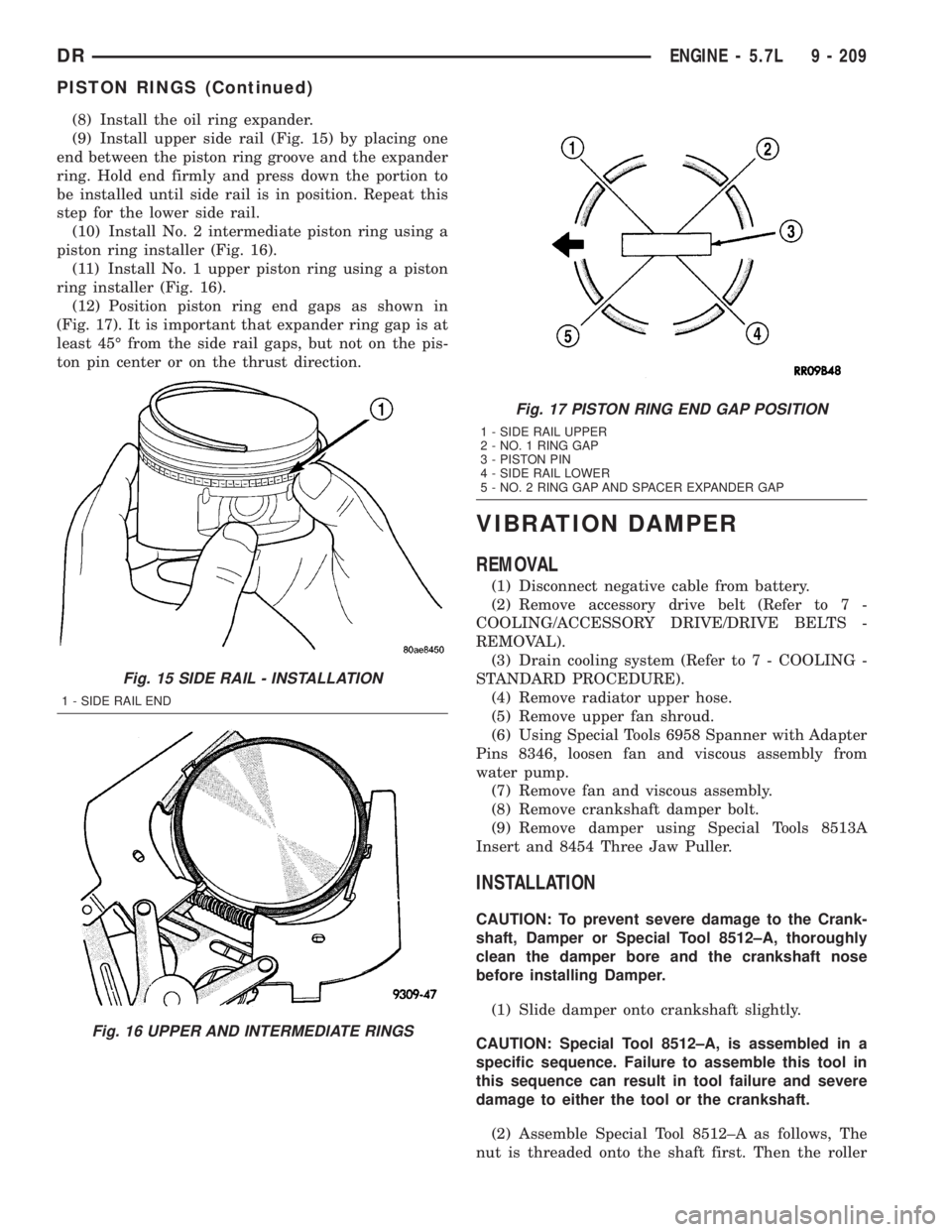
(9) Install upper side rail (Fig. 15) by placing one
end between the piston ring groove and the expander
ring. Hold end firmly and press down the portion to
be installed until side rail is in position. Repeat this
step for the lower side rail.
(10) Install No. 2 intermediate piston ring using a
piston ring installer (Fig. 16).
(11) Install No. 1 upper piston ring using a piston
ring installer (Fig. 16).
(12) Position piston ring end gaps as shown in
(Fig. 17). It is important that expander ring gap is at
least 45É from the side rail gaps, but not on the pis-
ton pin center or on the thrust direction.
VIBRATION DAMPER
REMOVAL
(1) Disconnect negative cable from battery.
(2) Remove accessory drive belt (Refer to 7 -
COOLING/ACCESSORY DRIVE/DRIVE BELTS -
REMOVAL).
(3) Drain cooling system (Refer to 7 - COOLING -
STANDARD PROCEDURE).
(4) Remove radiator upper hose.
(5) Remove upper fan shroud.
(6) Using Special Tools 6958 Spanner with Adapter
Pins 8346, loosen fan and viscous assembly from
water pump.
(7) Remove fan and viscous assembly.
(8) Remove crankshaft damper bolt.
(9) Remove damper using Special Tools 8513A
Insert and 8454 Three Jaw Puller.
INSTALLATION
CAUTION: To prevent severe damage to the Crank-
shaft, Damper or Special Tool 8512±A, thoroughly
clean the damper bore and the crankshaft nose
before installing Damper.
(1) Slide damper onto crankshaft slightly.
CAUTION: Special Tool 8512±A, is assembled in a
specific sequence. Failure to assemble this tool in
this sequence can result in tool failure and severe
damage to either the tool or the crankshaft.
(2) Assemble Special Tool 8512±A as follows, The
nut is threaded onto the shaft first. Then the roller
Fig. 15 SIDE RAIL - INSTALLATION
1 - SIDE RAIL END
Fig. 16 UPPER AND INTERMEDIATE RINGS
Fig. 17 PISTON RING END GAP POSITION
1 - SIDE RAIL UPPER
2 - NO. 1 RING GAP
3 - PISTON PIN
4 - SIDE RAIL LOWER
5 - NO. 2 RING GAP AND SPACER EXPANDER GAP
DRENGINE - 5.7L 9 - 209
PISTON RINGS (Continued)
Page 1466 of 2895
poration recommends a Mopartor equivalent oil
filter be used.
(1) Position a drain pan under the oil filter.
(2) Using a suitable oil filter wrench loosen filter.
(3) Rotate the oil filter counterclockwise to remove
it from the cylinder block oil filter boss.
(4) When filter separates from cylinder block oil
filter boss, tip gasket end upward to minimize oil
spill. Remove filter from vehicle.
NOTE: Make sure filter gasket was removed with fil-
ter.
(5) With a wiping cloth, clean the gasket sealing
surface of oil and grime.
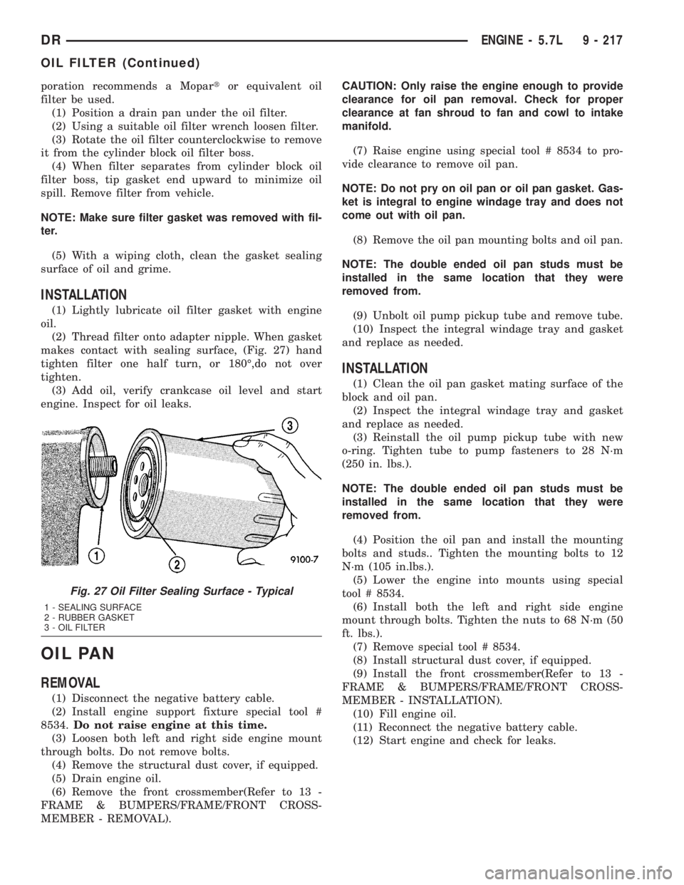
INSTALLATION
(1) Lightly lubricate oil filter gasket with engine
oil.
(2) Thread filter onto adapter nipple. When gasket
makes contact with sealing surface, (Fig. 27) hand
tighten filter one half turn, or 180É,do not over
tighten.
(3) Add oil, verify crankcase oil level and start
engine. Inspect for oil leaks.
OIL PAN
REMOVAL
(1) Disconnect the negative battery cable.
(2) Install engine support fixture special tool #
8534.Do not raise engine at this time.
(3) Loosen both left and right side engine mount
through bolts. Do not remove bolts.
(4) Remove the structural dust cover, if equipped.
(5) Drain engine oil.
(6) Remove the front crossmember(Refer to 13 -
FRAME & BUMPERS/FRAME/FRONT CROSS-
MEMBER - REMOVAL).CAUTION: Only raise the engine enough to provide
clearance for oil pan removal. Check for proper
clearance at fan shroud to fan and cowl to intake
manifold.
(7) Raise engine using special tool # 8534 to pro-
vide clearance to remove oil pan.
NOTE: Do not pry on oil pan or oil pan gasket. Gas-
ket is integral to engine windage tray and does not
come out with oil pan.
(8) Remove the oil pan mounting bolts and oil pan.
NOTE: The double ended oil pan studs must be
installed in the same location that they were
removed from.
(9) Unbolt oil pump pickup tube and remove tube.
(10) Inspect the integral windage tray and gasket
and replace as needed.
INSTALLATION
(1) Clean the oil pan gasket mating surface of the
block and oil pan.
(2) Inspect the integral windage tray and gasket
and replace as needed.
(3) Reinstall the oil pump pickup tube with new
o-ring. Tighten tube to pump fasteners to 28 N´m
(250 in. lbs.).
NOTE: The double ended oil pan studs must be
installed in the same location that they were
removed from.
(4) Position the oil pan and install the mounting
bolts and studs.. Tighten the mounting bolts to 12
N´m (105 in.lbs.).
(5) Lower the engine into mounts using special
tool # 8534.
(6) Install both the left and right side engine
mount through bolts. Tighten the nuts to 68 N´m (50
ft. lbs.).
(7) Remove special tool # 8534.
(8) Install structural dust cover, if equipped.
(9) Install the front crossmember(Refer to 13 -
FRAME & BUMPERS/FRAME/FRONT CROSS-
MEMBER - INSTALLATION).
(10) Fill engine oil.
(11) Reconnect the negative battery cable.
(12) Start engine and check for leaks.
Fig. 27 Oil Filter Sealing Surface - Typical
1 - SEALING SURFACE
2 - RUBBER GASKET
3 - OIL FILTER
DRENGINE - 5.7L 9 - 217
OIL FILTER (Continued)
Page 1467 of 2895
OIL PUMP
REMOVAL
(1) Remove the oil pan and pick-up tube(Refer to 9
- ENGINE/LUBRICATION/OIL PAN - REMOVAL).
(2) Remove the timing chain cover(Refer to 9 -
ENGINE/VALVE TIMING/TIMING BELT / CHAIN
COVER(S) - REMOVAL).
(3) Remove the four bolts, and the oil pump.
CLEANING
(1) Wash all parts in a suitable solvent.
INSPECTION
CAUTION: Oil pump pressure relief valve and
spring should not be removed from the oil pump. If
these components are disassembled and or
removed from the pump the entire oil pump assem-
bly must be replaced.
(1) Remove the pump cover.
(2) Clean all parts thoroughly. Mating surface of
the oil pump housing should be smooth. If the pump
cover is scratched or grooved the oil pump assembly
should be replaced.
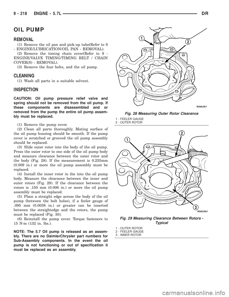
(3) Slide outer rotor into the body of the oil pump.
Press the outer rotor to one side of the oil pump body
and measure clearance between the outer rotor and
the body (Fig. 28). If the measurement is 0.235mm
(0.009 in.) or more the oil pump assembly must be
replaced.
(4) Install the inner rotor in the into the oil pump
body. Measure the clearance between the inner and
outer rotors (Fig. 29). If the clearance between the
rotors is .150 mm (0.006 in.) or more the oil pump
assembly must be replaced.
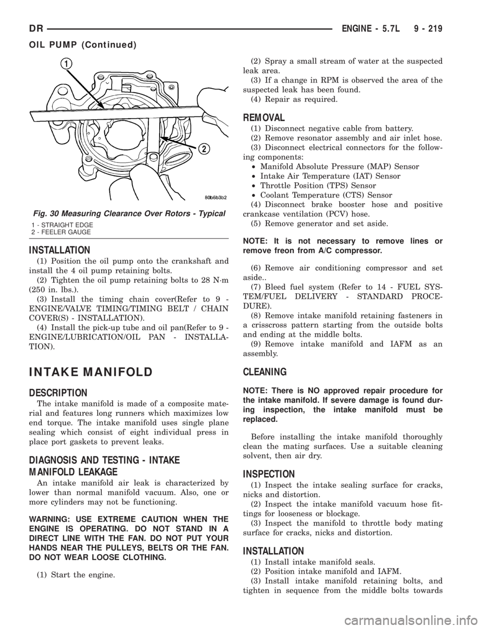
(5) Place a straight edge across the body of the oil
pump (between the bolt holes), if a feeler gauge of
.095 mm (0.0038 in.) or greater can be inserted
between the straightedge and the rotors, the pump
must be replaced (Fig. 30).
(6) Reinstall the pump cover. Torque fasteners to
15 N´m (132 in. lbs.).
NOTE: The 5.7 Oil pump is released as an assem-
bly. There are no DaimlerChrysler part numbers for
Sub-Assembly components. In the event the oil
pump is not functioning or out of specification it
must be replaced as an assembly.
Fig. 28 Measuring Outer Rotor Clearance
1 - FEELER GAUGE
2 - OUTER ROTOR
Fig. 29 Measuring Clearance Between Rotors -
Typical
1 - OUTER ROTOR
2 - FEELER GAUGE
3 - INNER ROTOR
9 - 218 ENGINE - 5.7LDR
Page 1468 of 2895
INSTALLATION
(1) Position the oil pump onto the crankshaft and
install the 4 oil pump retaining bolts.
(2) Tighten the oil pump retaining bolts to 28 N´m
(250 in. lbs.).
(3) Install the timing chain cover(Refer to 9 -
ENGINE/VALVE TIMING/TIMING BELT / CHAIN
COVER(S) - INSTALLATION).
(4) Install the pick-up tube and oil pan(Refer to 9 -
ENGINE/LUBRICATION/OIL PAN - INSTALLA-
TION).
INTAKE MANIFOLD
DESCRIPTION
The intake manifold is made of a composite mate-
rial and features long runners which maximizes low
end torque. The intake manifold uses single plane
sealing which consist of eight individual press in
place port gaskets to prevent leaks.
DIAGNOSIS AND TESTING - INTAKE
MANIFOLD LEAKAGE
An intake manifold air leak is characterized by
lower than normal manifold vacuum. Also, one or
more cylinders may not be functioning.
WARNING: USE EXTREME CAUTION WHEN THE
ENGINE IS OPERATING. DO NOT STAND IN A
DIRECT LINE WITH THE FAN. DO NOT PUT YOUR
HANDS NEAR THE PULLEYS, BELTS OR THE FAN.
DO NOT WEAR LOOSE CLOTHING.
(1) Start the engine.(2) Spray a small stream of water at the suspected
leak area.
(3) If a change in RPM is observed the area of the
suspected leak has been found.
(4) Repair as required.
REMOVAL
(1) Disconnect negative cable from battery.
(2) Remove resonator assembly and air inlet hose.
(3) Disconnect electrical connectors for the follow-
ing components:
²Manifold Absolute Pressure (MAP) Sensor
²Intake Air Temperature (IAT) Sensor
²Throttle Position (TPS) Sensor
²Coolant Temperature (CTS) Sensor
(4) Disconnect brake booster hose and positive
crankcase ventilation (PCV) hose.
(5) Remove generator and set aside.
NOTE: It is not necessary to remove lines or
remove freon from A/C compressor.
(6) Remove air conditioning compressor and set
aside..
(7) Bleed fuel system (Refer to 14 - FUEL SYS-
TEM/FUEL DELIVERY - STANDARD PROCE-
DURE).
(8) Remove intake manifold retaining fasteners in
a crisscross pattern starting from the outside bolts
and ending at the middle bolts.
(9) Remove intake manifold and IAFM as an
assembly.
CLEANING
NOTE: There is NO approved repair procedure for
the intake manifold. If severe damage is found dur-
ing inspection, the intake manifold must be
replaced.
Before installing the intake manifold thoroughly
clean the mating surfaces. Use a suitable cleaning
solvent, then air dry.
INSPECTION
(1) Inspect the intake sealing surface for cracks,
nicks and distortion.
(2) Inspect the intake manifold vacuum hose fit-
tings for looseness or blockage.
(3) Inspect the manifold to throttle body mating
surface for cracks, nicks and distortion.
INSTALLATION
(1) Install intake manifold seals.
(2) Position intake manifold and IAFM.
(3) Install intake manifold retaining bolts, and
tighten in sequence from the middle bolts towards
Fig. 30 Measuring Clearance Over Rotors - Typical
1 - STRAIGHT EDGE
2 - FEELER GAUGE
DRENGINE - 5.7L 9 - 219
OIL PUMP (Continued)
Page 1470 of 2895
(14) Remove crankshaft damper(Refer to 9 -
ENGINE/ENGINE BLOCK/VIBRATION DAMPER -
REMOVAL).
NOTE: Do not remove the hoses from the power
steering pump.
(15) Remove power steering pump and set aside.
(16) Remove the dipstick support bolt.
(17) Drain the engine oil.
(18) Remove the oil pan and pick up tube(Refer to
9 - ENGINE/LUBRICATION/OIL PAN - REMOVAL).
NOTE: It is not necessary to remove water pump for
timing cover removal.
(19) Remove timing cover bolts and remove cover.
INSTALLATION
(1) Clean timing chain cover and block surface.
NOTE: Always install a new gasket on timing cover.
(2) Install cover and new gasket. Tighten fasteners
to 28 N´m (250 in. lbs.).
NOTE: The large lifting stud is torqued to 55 N´m
(40 ft. lbs.).
(3) Install the oil pan and pick up tube(Refer to 9 -
ENGINE/LUBRICATION/OIL PAN - INSTALLA-
TION).
(4) Install the A/C compressor.
(5) Install the generator.
(6) Install power steering pump.
(7) Install the dipstick support bolt.
(8) Install the thermostat housing.
(9) Install crankshaft damper(Refer to 9 -
ENGINE/ENGINE BLOCK/VIBRATION DAMPER -
INSTALLATION).
(10) Install accessory drive belt tensioner assembly
and both idler pulleys.
(11) Install radiator lower hose.
(12) Install both heater hoses.
(13) Install radiator fan shroud.
(14) Install the fan and fan drive assembly
(15) Install the accessory drive belt.
(16) Install the coolant bottle and washer bottle.
(17) Install the upper radiator hose.
(18) Install the air cleaner assembly.
(19) Fill cooling system.
(20) Refill engine oil.
(21) Connect the battery negative cable.
TIMING/CHAIN AND
SPROCKETS
REMOVAL
(1) Disconnect battery negative cable.
(2) Drain cooling system.
(3) Remove Timing Chain Cover.
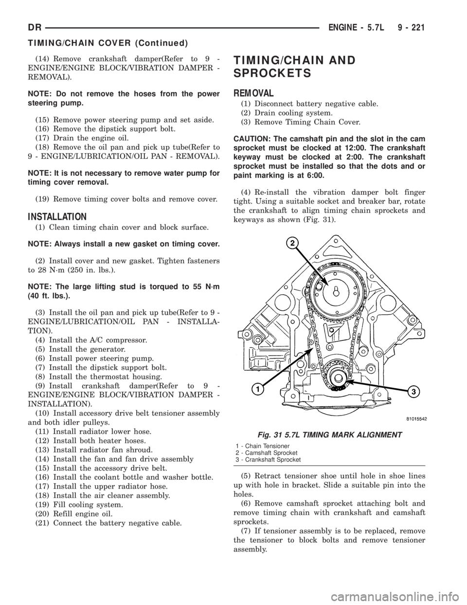
CAUTION: The camshaft pin and the slot in the cam
sprocket must be clocked at 12:00. The crankshaft
keyway must be clocked at 2:00. The crankshaft
sprocket must be installed so that the dots and or
paint marking is at 6:00.
(4) Re-install the vibration damper bolt finger
tight. Using a suitable socket and breaker bar, rotate
the crankshaft to align timing chain sprockets and
keyways as shown (Fig. 31).
(5) Retract tensioner shoe until hole in shoe lines
up with hole in bracket. Slide a suitable pin into the
holes.
(6) Remove camshaft sprocket attaching bolt and
remove timing chain with crankshaft and camshaft
sprockets.
(7) If tensioner assembly is to be replaced, remove
the tensioner to block bolts and remove tensioner
assembly.
Fig. 31 5.7L TIMING MARK ALIGNMENT
1 - Chain Tensioner
2 - Camshaft Sprocket
3 - Crankshaft Sprocket
DRENGINE - 5.7L 9 - 221
TIMING/CHAIN COVER (Continued)