2003 DODGE RAM Engine system
[x] Cancel search: Engine systemPage 434 of 2895
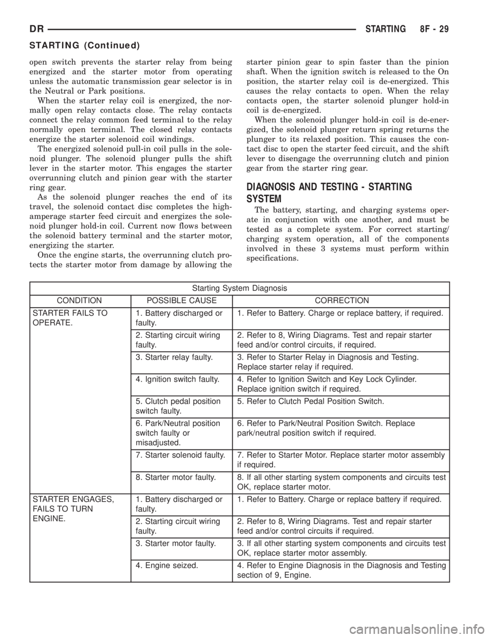
open switch prevents the starter relay from being
energized and the starter motor from operating
unless the automatic transmission gear selector is in
the Neutral or Park positions.
When the starter relay coil is energized, the nor-
mally open relay contacts close. The relay contacts
connect the relay common feed terminal to the relay
normally open terminal. The closed relay contacts
energize the starter solenoid coil windings.
The energized solenoid pull-in coil pulls in the sole-
noid plunger. The solenoid plunger pulls the shift
lever in the starter motor. This engages the starter
overrunning clutch and pinion gear with the starter
ring gear.
As the solenoid plunger reaches the end of its
travel, the solenoid contact disc completes the high-
amperage starter feed circuit and energizes the sole-
noid plunger hold-in coil. Current now flows between
the solenoid battery terminal and the starter motor,
energizing the starter.
Once the engine starts, the overrunning clutch pro-
tects the starter motor from damage by allowing thestarter pinion gear to spin faster than the pinion
shaft. When the ignition switch is released to the On
position, the starter relay coil is de-energized. This
causes the relay contacts to open. When the relay
contacts open, the starter solenoid plunger hold-in
coil is de-energized.
When the solenoid plunger hold-in coil is de-ener-
gized, the solenoid plunger return spring returns the
plunger to its relaxed position. This causes the con-
tact disc to open the starter feed circuit, and the shift
lever to disengage the overrunning clutch and pinion
gear from the starter ring gear.
DIAGNOSIS AND TESTING - STARTING
SYSTEM
The battery, starting, and charging systems oper-
ate in conjunction with one another, and must be
tested as a complete system. For correct starting/
charging system operation, all of the components
involved in these 3 systems must perform within
specifications.
Starting System Diagnosis
CONDITION POSSIBLE CAUSE CORRECTION
STARTER FAILS TO
OPERATE.1. Battery discharged or
faulty.1. Refer to Battery. Charge or replace battery, if required.
2. Starting circuit wiring
faulty.2. Refer to 8, Wiring Diagrams. Test and repair starter
feed and/or control circuits, if required.
3. Starter relay faulty. 3. Refer to Starter Relay in Diagnosis and Testing.
Replace starter relay if required.
4. Ignition switch faulty. 4. Refer to Ignition Switch and Key Lock Cylinder.
Replace ignition switch if required.
5. Clutch pedal position
switch faulty.5. Refer to Clutch Pedal Position Switch.
6. Park/Neutral position
switch faulty or
misadjusted.6. Refer to Park/Neutral Position Switch. Replace
park/neutral position switch if required.
7. Starter solenoid faulty. 7. Refer to Starter Motor. Replace starter motor assembly
if required.
8. Starter motor faulty. 8. If all other starting system components and circuits test
OK, replace starter motor.
STARTER ENGAGES,
FAILS TO TURN
ENGINE.1. Battery discharged or
faulty.1. Refer to Battery. Charge or replace battery if required.
2. Starting circuit wiring
faulty.2. Refer to 8, Wiring Diagrams. Test and repair starter
feed and/or control circuits if required.
3. Starter motor faulty. 3. If all other starting system components and circuits test
OK, replace starter motor assembly.
4. Engine seized. 4. Refer to Engine Diagnosis in the Diagnosis and Testing
section of 9, Engine.
DRSTARTING 8F - 29
STARTING (Continued)
Page 435 of 2895
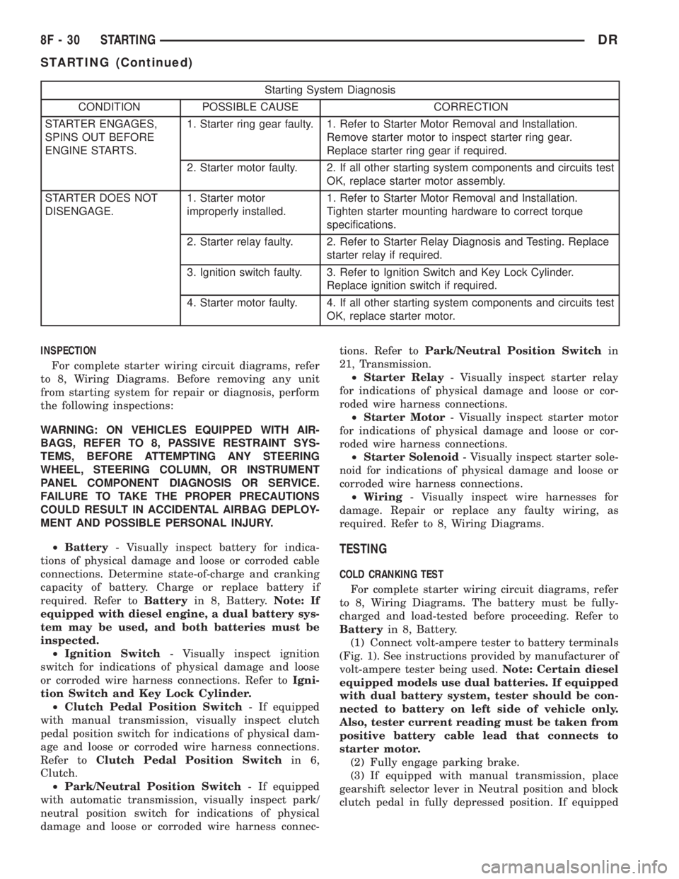
Starting System Diagnosis
CONDITION POSSIBLE CAUSE CORRECTION
STARTER ENGAGES,
SPINS OUT BEFORE
ENGINE STARTS.1. Starter ring gear faulty. 1. Refer to Starter Motor Removal and Installation.
Remove starter motor to inspect starter ring gear.
Replace starter ring gear if required.
2. Starter motor faulty. 2. If all other starting system components and circuits test
OK, replace starter motor assembly.
STARTER DOES NOT
DISENGAGE.1. Starter motor
improperly installed.1. Refer to Starter Motor Removal and Installation.
Tighten starter mounting hardware to correct torque
specifications.
2. Starter relay faulty. 2. Refer to Starter Relay Diagnosis and Testing. Replace
starter relay if required.
3. Ignition switch faulty. 3. Refer to Ignition Switch and Key Lock Cylinder.
Replace ignition switch if required.
4. Starter motor faulty. 4. If all other starting system components and circuits test
OK, replace starter motor.
INSPECTION
For complete starter wiring circuit diagrams, refer
to 8, Wiring Diagrams. Before removing any unit
from starting system for repair or diagnosis, perform
the following inspections:
WARNING: ON VEHICLES EQUIPPED WITH AIR-
BAGS, REFER TO 8, PASSIVE RESTRAINT SYS-
TEMS, BEFORE ATTEMPTING ANY STEERING
WHEEL, STEERING COLUMN, OR INSTRUMENT
PANEL COMPONENT DIAGNOSIS OR SERVICE.
FAILURE TO TAKE THE PROPER PRECAUTIONS
COULD RESULT IN ACCIDENTAL AIRBAG DEPLOY-
MENT AND POSSIBLE PERSONAL INJURY.
²Battery- Visually inspect battery for indica-
tions of physical damage and loose or corroded cable
connections. Determine state-of-charge and cranking
capacity of battery. Charge or replace battery if
required. Refer toBatteryin 8, Battery.Note: If
equipped with diesel engine, a dual battery sys-
tem may be used, and both batteries must be
inspected.
²Ignition Switch- Visually inspect ignition
switch for indications of physical damage and loose
or corroded wire harness connections. Refer toIgni-
tion Switch and Key Lock Cylinder.
²Clutch Pedal Position Switch- If equipped
with manual transmission, visually inspect clutch
pedal position switch for indications of physical dam-
age and loose or corroded wire harness connections.
Refer toClutch Pedal Position Switchin 6,
Clutch.
²Park/Neutral Position Switch- If equipped
with automatic transmission, visually inspect park/
neutral position switch for indications of physical
damage and loose or corroded wire harness connec-tions. Refer toPark/Neutral Position Switchin
21, Transmission.
²Starter Relay- Visually inspect starter relay
for indications of physical damage and loose or cor-
roded wire harness connections.
²Starter Motor- Visually inspect starter motor
for indications of physical damage and loose or cor-
roded wire harness connections.
²Starter Solenoid- Visually inspect starter sole-
noid for indications of physical damage and loose or
corroded wire harness connections.
²Wiring- Visually inspect wire harnesses for
damage. Repair or replace any faulty wiring, as
required. Refer to 8, Wiring Diagrams.
TESTING
COLD CRANKING TEST
For complete starter wiring circuit diagrams, refer
to 8, Wiring Diagrams. The battery must be fully-
charged and load-tested before proceeding. Refer to
Batteryin 8, Battery.
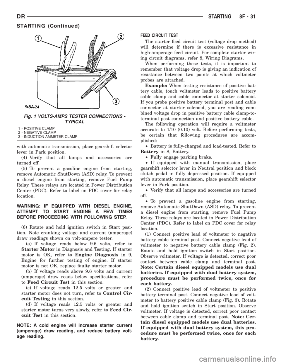
(1) Connect volt-ampere tester to battery terminals
(Fig. 1). See instructions provided by manufacturer of
volt-ampere tester being used.Note: Certain diesel
equipped models use dual batteries. If equipped
with dual battery system, tester should be con-
nected to battery on left side of vehicle only.
Also, tester current reading must be taken from
positive battery cable lead that connects to
starter motor.
(2) Fully engage parking brake.
(3) If equipped with manual transmission, place
gearshift selector lever in Neutral position and block
clutch pedal in fully depressed position. If equipped
8F - 30 STARTINGDR
STARTING (Continued)
Page 436 of 2895
with automatic transmission, place gearshift selector
lever in Park position.
(4) Verify that all lamps and accessories are
turned off.
(5) To prevent a gasoline engine from starting,
remove Automatic ShutDown (ASD) relay. To prevent
a diesel engine from starting, remove Fuel Pump
Relay. These relays are located in Power Distribution
Center (PDC). Refer to label on PDC cover for relay
location.
WARNING: IF EQUIPPED WITH DIESEL ENGINE,
ATTEMPT TO START ENGINE A FEW TIMES
BEFORE PROCEEDING WITH FOLLOWING STEP.
(6) Rotate and hold ignition switch in Start posi-
tion. Note cranking voltage and current (amperage)
draw readings shown on volt-ampere tester.
(a) If voltage reads below 9.6 volts, refer to
Starter Motorin Diagnosis and Testing. If starter
motor is OK, refer toEngine Diagnosisin 9,
Engine for further testing of engine. If starter
motor is not OK, replace faulty starter motor.
(b) If voltage reads above 9.6 volts and current
(amperage) draw reads below specifications, refer
toFeed Circuit Testin this section.
(c) If voltage reads 12.5 volts or greater and
starter motor does not turn, refer toControl Cir-
cuit Testingin this section.
(d) If voltage reads 12.5 volts or greater and
starter motor turns very slowly, refer toFeed Cir-
cuit Testin this section.
NOTE: A cold engine will increase starter current
(amperage) draw reading, and reduce battery volt-
age reading.FEED CIRCUIT TEST
The starter feed circuit test (voltage drop method)
will determine if there is excessive resistance in
high-amperage feed circuit. For complete starter wir-
ing circuit diagrams, refer 8, Wiring Diagrams.
When performing these tests, it is important to
remember that voltage drop is giving an indication of
resistance between two points at which voltmeter
probes are attached.
Example:When testing resistance of positive bat-
tery cable, touch voltmeter leads to positive battery
cable clamp and cable connector at starter solenoid.
If you probe positive battery terminal post and cable
connector at starter solenoid, you are reading com-
bined voltage drop in positive battery cable clamp-to-
terminal post connection and positive battery cable.
The following operation will require a voltmeter
accurate to 1/10 (0.10) volt. Before performing tests,
be certain that following procedures are accom-
plished:
²Battery is fully-charged and load-tested. Refer to
Batteryin 8, Battery.
²Fully engage parking brake.
²If equipped with manual transmission, place
gearshift selector lever in Neutral position and block
clutch pedal in fully depressed position. If equipped
with automatic transmission, place gearshift selector
lever in Park position.
²Verify that all lamps and accessories are turned
off.
²To prevent a gasoline engine from starting,
remove Automatic ShutDown (ASD) relay. To prevent
a diesel engine from starting, remove Fuel Pump
Relay. These relays are located in Power Distribution
Center (PDC). Refer to label on PDC cover for relay
location.
(1) Connect positive lead of voltmeter to negative
battery cable terminal post. Connect negative lead of
voltmeter to negative battery cable clamp (Fig. 2).
Rotate and hold ignition switch in Start position.
Observe voltmeter. If voltage is detected, correct poor
contact between cable clamp and terminal post.
Note: Certain diesel equipped models use dual
batteries. If equipped with dual battery system,
procedure must be performed twice, once for
each battery.
(2) Connect positive lead of voltmeter to positive
battery terminal post. Connect negative lead of volt-
meter to battery positive cable clamp (Fig. 3). Rotate
and hold ignition switch in Start position. Observe
voltmeter. If voltage is detected, correct poor contact
between cable clamp and terminal post.Note: Cer-
tain diesel equipped models use dual batteries.
If equipped with dual battery system, this pro-
cedure must be performed twice, once for each
battery.
Fig. 1 VOLTS-AMPS TESTER CONNECTIONS -
TYPICAL
1 - POSITIVE CLAMP
2 - NEGATIVE CLAMP
3 - INDUCTION AMMETER CLAMP
DRSTARTING 8F - 31
STARTING (Continued)
Page 437 of 2895
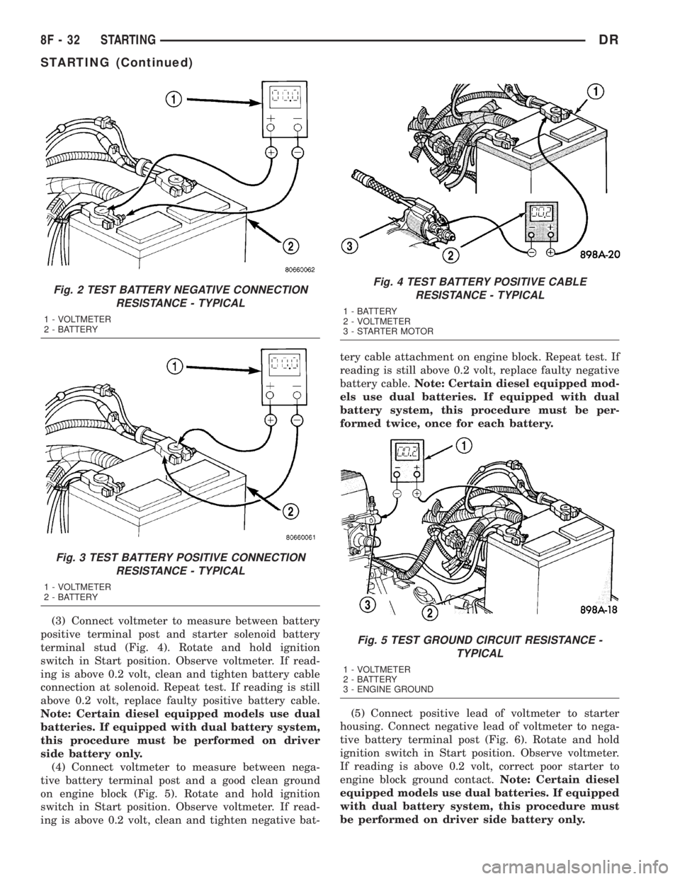
(3) Connect voltmeter to measure between battery
positive terminal post and starter solenoid battery
terminal stud (Fig. 4). Rotate and hold ignition
switch in Start position. Observe voltmeter. If read-
ing is above 0.2 volt, clean and tighten battery cable
connection at solenoid. Repeat test. If reading is still
above 0.2 volt, replace faulty positive battery cable.
Note: Certain diesel equipped models use dual
batteries. If equipped with dual battery system,
this procedure must be performed on driver
side battery only.
(4) Connect voltmeter to measure between nega-
tive battery terminal post and a good clean ground
on engine block (Fig. 5). Rotate and hold ignition
switch in Start position. Observe voltmeter. If read-
ing is above 0.2 volt, clean and tighten negative bat-tery cable attachment on engine block. Repeat test. If
reading is still above 0.2 volt, replace faulty negative
battery cable.Note: Certain diesel equipped mod-
els use dual batteries. If equipped with dual
battery system, this procedure must be per-
formed twice, once for each battery.
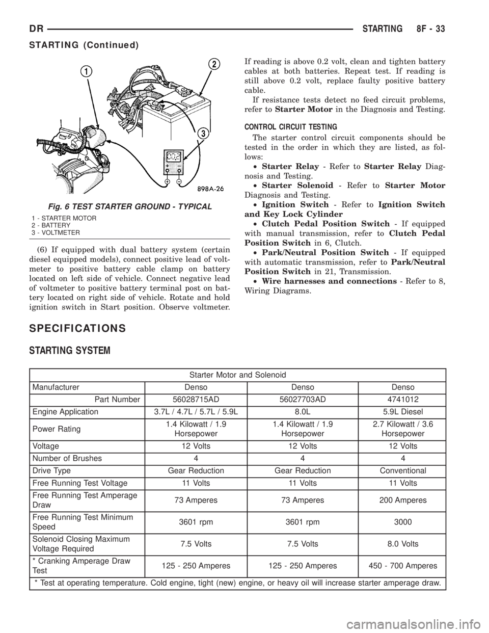
(5) Connect positive lead of voltmeter to starter
housing. Connect negative lead of voltmeter to nega-
tive battery terminal post (Fig. 6). Rotate and hold
ignition switch in Start position. Observe voltmeter.
If reading is above 0.2 volt, correct poor starter to
engine block ground contact.Note: Certain diesel
equipped models use dual batteries. If equipped
with dual battery system, this procedure must
be performed on driver side battery only.
Fig. 2 TEST BATTERY NEGATIVE CONNECTION
RESISTANCE - TYPICAL
1 - VOLTMETER
2 - BATTERY
Fig. 3 TEST BATTERY POSITIVE CONNECTION
RESISTANCE - TYPICAL
1 - VOLTMETER
2 - BATTERY
Fig. 4 TEST BATTERY POSITIVE CABLE
RESISTANCE - TYPICAL
1 - BATTERY
2 - VOLTMETER
3 - STARTER MOTOR
Fig. 5 TEST GROUND CIRCUIT RESISTANCE -
TYPICAL
1 - VOLTMETER
2 - BATTERY
3 - ENGINE GROUND
8F - 32 STARTINGDR
STARTING (Continued)
Page 438 of 2895
(6) If equipped with dual battery system (certain
diesel equipped models), connect positive lead of volt-
meter to positive battery cable clamp on battery
located on left side of vehicle. Connect negative lead
of voltmeter to positive battery terminal post on bat-
tery located on right side of vehicle. Rotate and hold
ignition switch in Start position. Observe voltmeter.If reading is above 0.2 volt, clean and tighten battery
cables at both batteries. Repeat test. If reading is
still above 0.2 volt, replace faulty positive battery
cable.
If resistance tests detect no feed circuit problems,
refer toStarter Motorin the Diagnosis and Testing.
CONTROL CIRCUIT TESTING
The starter control circuit components should be
tested in the order in which they are listed, as fol-
lows:
²Starter Relay- Refer toStarter RelayDiag-
nosis and Testing.
²Starter Solenoid- Refer toStarter Motor
Diagnosis and Testing.
²Ignition Switch- Refer toIgnition Switch
and Key Lock Cylinder
²Clutch Pedal Position Switch- If equipped
with manual transmission, refer toClutch Pedal
Position Switchin 6, Clutch.
²Park/Neutral Position Switch- If equipped
with automatic transmission, refer toPark/Neutral
Position Switchin 21, Transmission.
²Wire harnesses and connections- Refer to 8,
Wiring Diagrams.
SPECIFICATIONS
STARTING SYSTEM
Starter Motor and Solenoid
Manufacturer Denso Denso Denso
Part Number 56028715AD 56027703AD 4741012
Engine Application 3.7L / 4.7L / 5.7L / 5.9L 8.0L 5.9L Diesel
Power Rating1.4 Kilowatt / 1.9
Horsepower1.4 Kilowatt / 1.9
Horsepower2.7 Kilowatt / 3.6
Horsepower
Voltage 12 Volts 12 Volts 12 Volts
Number of Brushes 4 4 4
Drive Type Gear Reduction Gear Reduction Conventional
Free Running Test Voltage 11 Volts 11 Volts 11 Volts
Free Running Test Amperage
Draw73 Amperes 73 Amperes 200 Amperes
Free Running Test Minimum
Speed3601 rpm 3601 rpm 3000
Solenoid Closing Maximum
Voltage Required7.5 Volts 7.5 Volts 8.0 Volts
* Cranking Amperage Draw
Test125 - 250 Amperes 125 - 250 Amperes 450 - 700 Amperes
* Test at operating temperature. Cold engine, tight (new) engine, or heavy oil will increase starter amperage draw.
Fig. 6 TEST STARTER GROUND - TYPICAL
1 - STARTER MOTOR
2 - BATTERY
3 - VOLTMETER
DRSTARTING 8F - 33
STARTING (Continued)
Page 439 of 2895
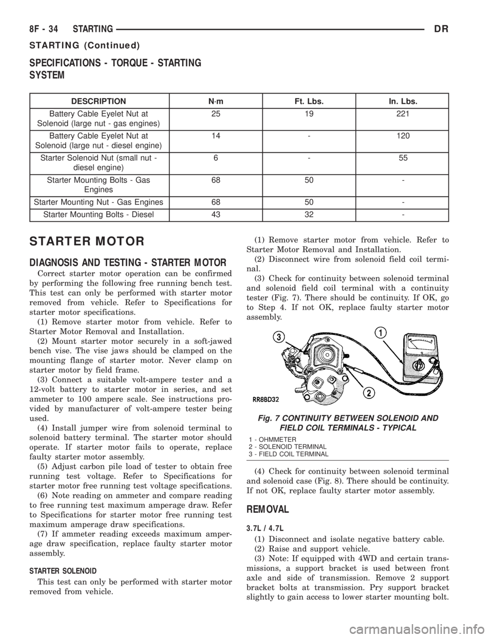
SPECIFICATIONS - TORQUE - STARTING
SYSTEM
DESCRIPTION N´m Ft. Lbs. In. Lbs.
Battery Cable Eyelet Nut at
Solenoid (large nut - gas engines)25 19 221
Battery Cable Eyelet Nut at
Solenoid (large nut - diesel engine)14 - 120
Starter Solenoid Nut (small nut -
diesel engine)6-55
Starter Mounting Bolts - Gas
Engines68 50 -
Starter Mounting Nut - Gas Engines 68 50 -
Starter Mounting Bolts - Diesel 43 32 -
STARTER MOTOR
DIAGNOSIS AND TESTING - STARTER MOTOR
Correct starter motor operation can be confirmed
by performing the following free running bench test.
This test can only be performed with starter motor
removed from vehicle. Refer to Specifications for
starter motor specifications.
(1) Remove starter motor from vehicle. Refer to
Starter Motor Removal and Installation.
(2) Mount starter motor securely in a soft-jawed
bench vise. The vise jaws should be clamped on the
mounting flange of starter motor. Never clamp on
starter motor by field frame.
(3) Connect a suitable volt-ampere tester and a
12-volt battery to starter motor in series, and set
ammeter to 100 ampere scale. See instructions pro-
vided by manufacturer of volt-ampere tester being
used.
(4) Install jumper wire from solenoid terminal to
solenoid battery terminal. The starter motor should
operate. If starter motor fails to operate, replace
faulty starter motor assembly.
(5) Adjust carbon pile load of tester to obtain free
running test voltage. Refer to Specifications for
starter motor free running test voltage specifications.
(6) Note reading on ammeter and compare reading
to free running test maximum amperage draw. Refer
to Specifications for starter motor free running test
maximum amperage draw specifications.
(7) If ammeter reading exceeds maximum amper-
age draw specification, replace faulty starter motor
assembly.
STARTER SOLENOID
This test can only be performed with starter motor
removed from vehicle.(1) Remove starter motor from vehicle. Refer to
Starter Motor Removal and Installation.
(2) Disconnect wire from solenoid field coil termi-
nal.
(3) Check for continuity between solenoid terminal
and solenoid field coil terminal with a continuity
tester (Fig. 7). There should be continuity. If OK, go
to Step 4. If not OK, replace faulty starter motor
assembly.
(4) Check for continuity between solenoid terminal
and solenoid case (Fig. 8). There should be continuity.
If not OK, replace faulty starter motor assembly.
REMOVAL
3.7L / 4.7L
(1) Disconnect and isolate negative battery cable.
(2) Raise and support vehicle.
(3) Note: If equipped with 4WD and certain trans-
missions, a support bracket is used between front
axle and side of transmission. Remove 2 support
bracket bolts at transmission. Pry support bracket
slightly to gain access to lower starter mounting bolt.
Fig. 7 CONTINUITY BETWEEN SOLENOID AND
FIELD COIL TERMINALS - TYPICAL
1 - OHMMETER
2 - SOLENOID TERMINAL
3 - FIELD COIL TERMINAL
8F - 34 STARTINGDR
STARTING (Continued)
Page 449 of 2895

OPERATION
The heated seat module receives fused battery cur-
rent through the Integrated Power Module only when
the engine is running. The heated seat switches
receive battery current through fuse #48 in the Inte-
grated Power Module only when the ignition switch
is in the On position. The heated seat module shares
a common ground circuit with each of the heated seat
elements. The heated seat system will only operate
when the surface temperature of the seat cushion is
below the designed temperature set points of the sys-
tem.
The heated seat system will also automatically
turn off whenever the ignition switch is turned to
any position except On, or if the engine quits run-
ning. If the ignition switch is turned to the Off posi-
tion or if the engine quits running while a heated
seat is ON, the heated seat will remain Off after the
engine is restarted until a heated seat switch is
depressed again. This helps prevent the vehicles bat-
tery from being drained by the heated seat system.The heated seat module monitors inputs from the
heated seat sensors and the heated seat switches. In
response to these inputs the heated seat module uses
its internal programming to control 12v to the heated
seat elements in both front seats and to control the
heated seat LED indicator lamps located in both of
the heated seat switches. The heated seat module is
also programmed to provide self-diagnostics, if a
problem with the heated seat system is detected. If
the module detects certain failures within the heated
seat system, it will provide a visual indication of the
failure by flashing the indicator lamps in the appro-
priate heated seat switch. The heated seat module
will automatically turn off the heated seat elements
if it detects a short or open in the heated seat ele-
ment circuit or a heated seat sensor value that is out
of range.
DIAGNOSIS AND TESTING - HEATED SEAT
SYSTEM
HEATED SEAT SYSTEM SELF-DIAGNOSIS
The heated seat system is capable of performing
some self-diagnostics. The following table depicts the
various monitored failures which will be reported to
the vehicle operator or technician by flashing the
individual heated seat switch Light Emitting Diode
(LED) indicator lamps. Refer to the HEATED SEAT
SYSTEM SELF-DIAGNOSIS table for failure identi-
fication. The drivers heated seat switch indicator
lamps will flash if a failure occurs in the driver
heated seat, and the passengers heated seat switch
indicator lamps will flash for a passenger heated seat
failure. If a monitored heated seat system failure
occurs, the switch indicator lamps will flash at a
pulse rate of about one-half second on, followed by
about one-half second off for a duration of about one
minute after the switch for the faulty heated seat is
depressed in either the Low or High direction. This
process will repeat every time the faulty heated seat
switch is actuated until the problem has been cor-
rected.
HEATED SEAT SYSTEM SELF-DIAGNOSIS
Monitored FailureSwitch High
Indicator LampSwitch Low
Indicator Lamp
Heated Seat
Element ShortedFlashing Flashing
Heated Seat
Element OpenFlashing Off
Heated Seat
Sensor Value Out
of RangeOff Flashing
Fig. 1 DR Heated Seat System Diagram
1 - WIRE HARNESS
2 - DRIVER HEATED SEAT SWITCH
3 - PASSENGER HEATED SEAT SWITCH
4 - PASSENGER HEATED SEAT CUSHION ELEMENT
5 - SEAT CUSHION/BACK ELEMENT ELECTRICAL CONNECTOR
LOCATION
6 - DRIVER HEATED SEAT BACK ELEMENT
7 - DRIVER HEATED SEAT CUSHION ELEMENT
8 - HEATED SEAT MODULE
8G - 4 HEATED SEAT SYSTEMDR
HEATED SEAT SYSTEM (Continued)
Page 456 of 2895
HORN
TABLE OF CONTENTS
page page
HORN SYSTEM
DESCRIPTION..........................1
OPERATION............................1
DIAGNOSIS AND TESTING - HORN SYSTEM . . . 1
HORN
DIAGNOSIS AND TESTING - HORN..........1REMOVAL.............................2
INSTALLATION..........................2
HORN SWITCH
DESCRIPTION..........................2
DIAGNOSIS AND TESTING - HORN SWITCH . . . 2
HORN SYSTEM
DESCRIPTION
The dual-note horn system features dual electro-
magnetic horn units. The horn system includes the
following major components:
²Horn- The two horns are located on the left
side of the engine compartment below the Integrated
Power Module (IPM).
²Horn Switch- The horn switch is molded into
the driver airbag trim cover.
OPERATION
The horn system operates on battery current
received through a fuse in the Integrated Power
Module (IPM). The horn system circuit is designed so
that the system will remain operational, regardless
of the ignition switch position.
DIAGNOSIS AND TESTING - HORN SYSTEM
The most reliable, efficient, and accurate
means to diagnose the horn system requires the
use of a DRBIIItscan tool and the proper Diag-
nostic Procedures manual. The DRBIIItscan
tool can provide confirmation that the PCI data
bus is functional, that all of the electronic mod-
ules are sending and receiving the proper mes-
sages on the PCI data bus, and that the horns
are being sent the proper hard wired outputs
for them to perform their functions.
Refer to the appropriate wiring information. The
wiring information includes wiring diagrams, proper
wire and connector repair procedures, details of wire
harness routing and retention, connector pin-out
information and location views for the various wire
harness connectors, splices and grounds.
In most cases, any problem involving continually
sounding horns can be quickly alleviated by removing
the horn fuse from the Integrated Power Module
(IPM).WARNING: DISABLE THE AIRBAG SYSTEM
BEFORE ATTEMPTING ANY STEERING WHEEL,
STEERING COLUMN, SEAT BELT TENSIONER, SIDE
AIRBAG, OR INSTRUMENT PANEL COMPONENT
DIAGNOSIS OR SERVICE. DISCONNECT AND ISO-
LATE THE BATTERY NEGATIVE (GROUND) CABLE,
THEN WAIT TWO MINUTES FOR THE AIRBAG SYS-
TEM CAPACITOR TO DISCHARGE BEFORE PER-
FORMING FURTHER DIAGNOSIS OR SERVICE. THIS
IS THE ONLY SURE WAY TO DISABLE THE AIRBAG
SYSTEM. FAILURE TO TAKE THE PROPER PRE-
CAUTIONS COULD RESULT IN ACCIDENTAL AIR-
BAG DEPLOYMENT AND POSSIBLE PERSONAL
INJURY.
HORN
DIAGNOSIS AND TESTING - HORN
The most reliable, efficient, and accurate
means to diagnose the horn system requires the
use of a DRBIIItscan tool and the proper Diag-
nostic Procedures manual. The DRBIIItscan
tool can provide confirmation that the PCI data
bus is functional, that all of the electronic mod-
ules are sending and receiving the proper mes-
sages on the PCI data bus, and that the horns
are being sent the proper hard wired outputs
for them to perform their functions.
Refer to the appropriate wiring information. The
wiring information includes wiring diagrams, proper
wire and connector repair procedures, details of wire
harness routing and retention, connector pin-out
information and location views for the various wire
harness connectors, splices and grounds.
DRHORN 8H - 1