Page 800 of 1184

7B–18 MANUAL CONTROL HEATING, VENTILATION, AND AIR CONDITIONING SYSTEM
DAEWOO M-150 BL2
D108B501
A/C PUSH KNOB
(Left–Hand Drive Shown, Right–Hand
Drive Similar)
Removal Procedure
1. Remove the instrument cluster housing trim panel.
Refer to Section 9E, Instrumentation/Driver Informa-
tion.
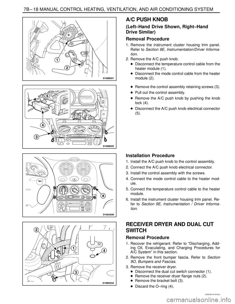
2. Remove the A/C push knob.
�Disconnect the temperature control cable from the
heater module (1).
�Disconnect the mode control cable from the heater
module (2).
D108B502
�Remove the control assembly retaining screws (3).
�Pull out the control assembly.
�Remove the A/C push knob by pushing the knob
lock (4).
�Disconnect the A/C push knob electrical connector
(5).
D108A506
Installation Procedure
1. Install the A/C push knob to the control assembly.
2. Connect the A/C push knob electrical connector.
3. Install the control assembly with the screws.
4. Connect the mode control cable to the heater mod-
ule.
5. Connect the temperature control cable to the heater
module.
6. Install the instrument cluster housing trim panel. Re-
fer to Section 9E, Instrumentation / Driver Informa-
tion.
D18B503A
RECEIVER DRYER AND DUAL CUT
SWITCH
Removal Procedure
1. Recover the refrigerant. Refer to “Discharging, Add-
ing Oil, Evaculating, and Charging Procedures for
A/C System” in this section.
2. Remove the front bumper fascia. Refer to Section
9O, Bumpers and Fascias.
3. Remove the receiver dryer.
�Disconnect the dual cut switch connector (1).
�Remove the receiver dryer flange nuts (2).
�Remove the bracket bolt (3).
�Discard the O–ring (4).
Page 801 of 1184
MANUAL CONTROL HEATING, VENTILATION, AND AIR CONDITIONING SYSTEM 7B–19
DAEWOO M-150 BL2
D18B504A
4. Remove the dual cut switch.
�With the receiver dryer clothed, vise the receiver
dryer (1).
�Remove the dual cut switch (2).
�Discard the O–ring (3).
D18B505B
Installation Procedure
1. Install the new O–ring.
2. Install the dual cut switch.
Tighten the dual cut switch to 13 N�m (115 lb-in).
D18B506B
3. Install the receiver dryer.
�Install the new O–rings.
�Install the bracket bolt (1).
Tighten
Tighten the bracket bolt to 5 N�m (44 lb-in).
�Install the receiver dryer flange nuts (2).
Tighten
Tighten the receiver dryer flange nut to 14 N�m (10.5
lb-ft).
�Connect the dual cut switch connector.
4. Install the front bumper fascia. Refer to Section 9O,
Bumpers and Fascias.
5. Evacuate and recharge the system. Refer to “Dis-
charging, Adding Oil, Evacuating, and Charging Pro-
cedures for A/C System” in this section.
Page 802 of 1184

7B–20 MANUAL CONTROL HEATING, VENTILATION, AND AIR CONDITIONING SYSTEM
DAEWOO M-150 BL2
D108B507
RECEIVER DRYER BRACKET
Removal Procedure
1. Remove the front bumper fascia. Refer to Section
9O, Bumpers and Fascias.
2. Remove the receiver dryer bracket.
�Remove the receiver dryer bracket bolt (1).
�Remove the receiver dryer bracket–to–body bolts
(2).
D18B508B
Installation Procedure
1. Install the receiver dry bracket with the bolts.
Tighten
�Tighten the receiver dryer bracket–to–body bolts
to 5 N�m (44 lb-in) (1).
�Tighten the receiver dryer bracket bolt to 5 N�m
(44 lb-in) (2).
2. Install the front bumper fascia. Refer to Section 9O,
Bumpers and Fascias.
D108B509
D18B510A
COMPRESSOR
Removal Procedure
1. Remove the receiver dryer. Refer to “Receiver Dryer
and Dual Cut Switch” in this section.
2. Remove the A/C belt. Refer to Section 6B, Power
Steering Pump.
3. Remove the compressor.
�Discharge and recover the refrigerant. Refer to
“Discharging, Adding Oil, Evacuating, and Charg-
ing Provedures for A/C System” in this section.
�Remove the bolt securing the low pressure pipe
line to the compressor (1).
�Remove the bolt securing the high pressure pipe
line to the compressor (2).
�Disconnect the electrical connector (3).
�Remove the upper bolt mounting the compressor–
to–bracket (4).
�Remove the lower bolts mounting the compres-
sor–to–bracket (5).
Page 803 of 1184

MANUAL CONTROL HEATING, VENTILATION, AND AIR CONDITIONING SYSTEM 7B -- 21
DAEWOO M-150 BL2
D18B511B
Installation Procedure
1. Install the compressor with the mounting bolts.
Tighten
DTighten the compressor--to--bracket upper bolt to
20 NSm (15 lb-ft) (1).
DTighten the compressor--to--bracket lower bolts to
22 NSm (16 lb-ft) (2).
2. Connect the electrical connector.
D18B512A
3. Install the A/C high pressure pipe line to the compres-
sor with the bolt.
Tighten
Tighten the A/C high pressure pipe line bolt to 23 NSm
(17 lb-ft) (3).
4. Install the A/C low pressure pipe line to the compres-
sor with the bolt.
Tighten
Tighten the A/C low pressure pipe line bolt to 23 NSm
(17 lb-ft) (4).
5. Evacuate and charge the system. Refer to “Discharg-
ing, Adding Oil, Evacuating, and Charging Procedure
for A/C System” in this section.
6. Install the A/C belt. Refer toSection 6B, Power Steer-
ing Pump.
7. Install the receiver dryer. Refer to “Receiver Dryer
and Dual Cut Switch” in this section.
D18B513A
CONDENSER
1. Disconnect the negative battery cable.
2. Remove the front bumper fascia. Refer toSection
9O, Bumpers and Fascias.
3. Discharge and recover the refrigerant. Refer to “Dis-
charging, Adding Oil, Evacuating, and Charging Pro-
cedures for A/C system” in this section.
4. Remove the condenser.
DLoosen the condenser pipe--to--compressor pipe
fitting (1).
DLoosen the condenser pipe--to--receiver dryer pipe
fitting (2).
Page 804 of 1184

7B -- 22 MANUAL CONTROL HEATING, VENTILATION, AND AIR CONDITIONING SYSTEM
DAEWOO M-150 BL2
D18B514A
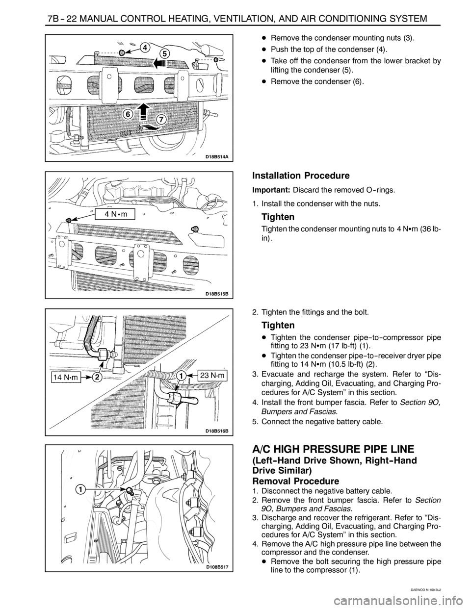
DRemove the condenser mounting nuts (3).
DPush the top of the condenser (4).
DTake off the condenser from the lower bracket by
lifting the condenser (5).
DRemove the condenser (6).
D18B515B
Installation Procedure
Important:Discard the removed O--rings.
1. Install the condenser with the nuts.
Tighten
Tighten the condenser mounting nuts to 4 NSm(36lb-
in).
D18B516B
2. Tighten the fittings and the bolt.
Tighten
DTighten the condenser pipe--to--compressor pipe
fitting to 23 NSm (17 lb-ft) (1).
DTighten the condenser pipe--to--receiver dryer pipe
fitting to 14 NSm (10.5 lb-ft) (2).
3. Evacuate and recharge the system. Refer to “Dis-
charging, Adding Oil, Evacuating, and Charging Pro-
cedures for A/C System” in this section.
4. Install the front bumper fascia. Refer toSection 9O,
Bumpers and Fascias.
5. Connect the negative battery cable.
D108B517
A/C HIGH PRESSURE PIPE LINE
(Left -- Hand Drive Shown, Right -- Hand
Drive Similar)
Removal Procedure
1. Disconnect the negative battery cable.
2. Remove the front bumper fascia. Refer toSection
9O, Bumpers and Fascias.
3. Discharge and recover the refrigerant. Refer to “Dis-
charging, Adding Oil, Evacuating, and Charging Pro-
cedures for A/C System” in this section.
4. Remove the A/C high pressure pipe line between the
compressor and the condenser.
DRemove the bolt securing the high pressure pipe
line to the compressor (1).
Page 805 of 1184
MANUAL CONTROL HEATING, VENTILATION, AND AIR CONDITIONING SYSTEM 7B -- 23
DAEWOO M-150 BL2
D18B518A
DLoosen the fitting securing the high pressure pipe
line to the condenser pipe line (2).
DRemove the clamp nut (3).
D18B519A
5. Remove the A/C high pressure pipe line between the
condenser and the receiver dryer.
DLoosen the fitting securing the receiver dryer to the
condenser (1).
D108B520
DRemove the receiver dryer flange nuts (2).
D18B521A
6. Remove the A/C high pressure pipe line between the
receiver dryer and the evaporator.
DRemove the purge control valve. Refer toSection
1F, Engine Controls.
DRemove the bracket nut (1).
DLoosen the fitting (2).
Page 806 of 1184

7B -- 24 MANUAL CONTROL HEATING, VENTILATION, AND AIR CONDITIONING SYSTEM
DAEWOO M-150 BL2
D18B522A
D18B523B
D18B524A
Installation Procedure
Important:Discard the removed O--rings.
1. Install the high pressure pipe lines with the bolts, the
nuts, and the fittings.
Tighten
DTighten the bolt securing the high pressure pipe
line to the compressor to 23 NSm (17 lb-ft) (1).
DTighten the fitting securing the high pressure pipe
line to the condenser pipe line to 23 NSm (17 lb-ft)
(2).
DTighten the fitting securing the high pressure pipe
line to the receiver dryer to 14 NSm (10.5 lb-ft) (3).
DTighten the bracket nut to 5 NSm (44 lb-in) (4).
DTighten the receiver dryer flange nuts to 14 NSm
(10.5 lb-ft) (5).
DTighten the nut securing the high pressure pipe line
to the evaporator to 14 NSm (10.5 lb-ft) (6).
DTighten the bracket nut to 5 NSm (44 lb-in) (7).
2. Install the purge control valve. Refer toSection 1F,
Engine controls.
3. Evacuate and recharge the system. Refer to “Dis-
charging, Adding Oil, Evaculating, and Charging Pro-
cedures for A/C System” in this section.
4. Install the front bumper fascia. Refer toSection 9O,
Bumpers and Fascias.
5. Connect the negative battery cable.
D18B525B
Page 807 of 1184
MANUAL CONTROL HEATING, VENTILATION, AND AIR CONDITIONING SYSTEM 7B -- 25
DAEWOO M-150 BL2
D108B526
A/C LOW PRESSURE PIPE LINE
(Left -- Hand Drive Shown, Right -- Hand
Drive Similar)
Removal Procedure
1. Disconnect the negative battery cable.
2. Discharge and recover the refrigerant. Refer to “Dis-
charging, Adding Oil, Evacuating, and Charging Pro-
cedures for A/C System” in this section.
3. Remove the A/C low pressure pipe line.
DRemove the bolt securing the A/C low pressure
pipe line at the compressor (1).
D18B527A
DRemove the bracket nut from shut bar (2).
D18B528A
DRemove the purge control valve. Refer toSection
1F, Engine Controls.
DLoosen the nut securing the A/C low pressure pipe
line at the evaporator (3).
D18B529B
Installation Procedure
Important:Discard the removed O--rings.
1. Install the A/C low pressure pipe line.
Tighten
DTighten the nut securing the A/C low pressure pipe
line at the evaporator to 14 NSm (10.5 lb-ft) (1).