Page 69 of 1184

ENGINE ELECTRICAL 1E–13
DAEWOO M-150 BL2
GENERATOR SYSTEM CHECK
When operating normally, the generator indicator lamp
will come on when the ignition switch is in the ON posi-
tion and go out when the engine starts. If the lamp oper-
ates abnormally or if an undercharged or overcharged
battery condition occurs, the following procedure may
be used to diagnose the charging system. Remember
that an undercharged battery is often caused by acces-
sories being left on overnight or by a defective switch
that allows a lamp, such as a trunk or glove box lamp, to
stay on.
Diagnose the generator with the following procedure:
1. Visually check the belt and wiring.
2. With the ignition switch in the ON position and the en-
gine stopped, the charge indicator lamp should be on.
If not, detach the harness at the generator and
ground the ‘‘L’’ terminal in the harness with a fused,
5-ampere jumper lead.�If the lamp lights, replace the generator. Refer to
“Generator” in the On-Vehicle Service section.
�If the lamp does not light, locate the open circuit
between the ignition switch and the harness con-
nector. The indicator lamp bulb may be burned out.
3. With the ignition switch in the ON position and the en-
gine running at moderate speed, the charge indicator
lamp should be off. If not, detach the wiring harness
at the generator.
�If the lamp goes off, replace the generator. Refer to
“Generator” in the On-Vehicle Service section.
�If the lamp stays on, check for a short to ground in
the harness between the connector and the indica-
tor lamp.
Important: Always check the generator for output be-
fore assuming that a grounded ‘‘L’’ terminal circuit has
damaged the regulator. Refer to “Generator” in the Unit
Repair section.
Page 768 of 1184
7A – 18 HEATING AND VENTILATION SYSTEM
DAEWOO M-150 BL2
REPAIR INSTRUCTIONS
ON-VEHICLE SERVICE
D108A502
D108A501
CONTROL ASSEMBLY AND
CONTROL CABLES
(Left–Hand Drive Shown, Right–Hand
Drive Similar)
Removal Procedure
1. Disconnect the negative battery cable.
2. Remove the instrument cluster housing trim panel.
Refer to Section 9E, Instrumentation/Driver informa-
tion.
3. Remove the control assembly.
�Remove the control assembly retaining screws (1).
�Separate the control assembly from the instrument
panel (2).
�Disconnect the electrical connectors (3).
�Disconnect the mode control cable from the heater
module (4).
�Disconnect the temperature control cable from the
heater module (5).
�Remove the glove box from the instrument panel.
Refer to Section 9E, Instrumentation/Driver Infor-
mation.
D108A503
�Disconnect the recirculating/fresh air door cable
from the blower module (6).
Page 769 of 1184
HEATING AND VENTILATION SYSTEM 7A–19
DAEWOO M-150 BL2
D108A504
D108A505
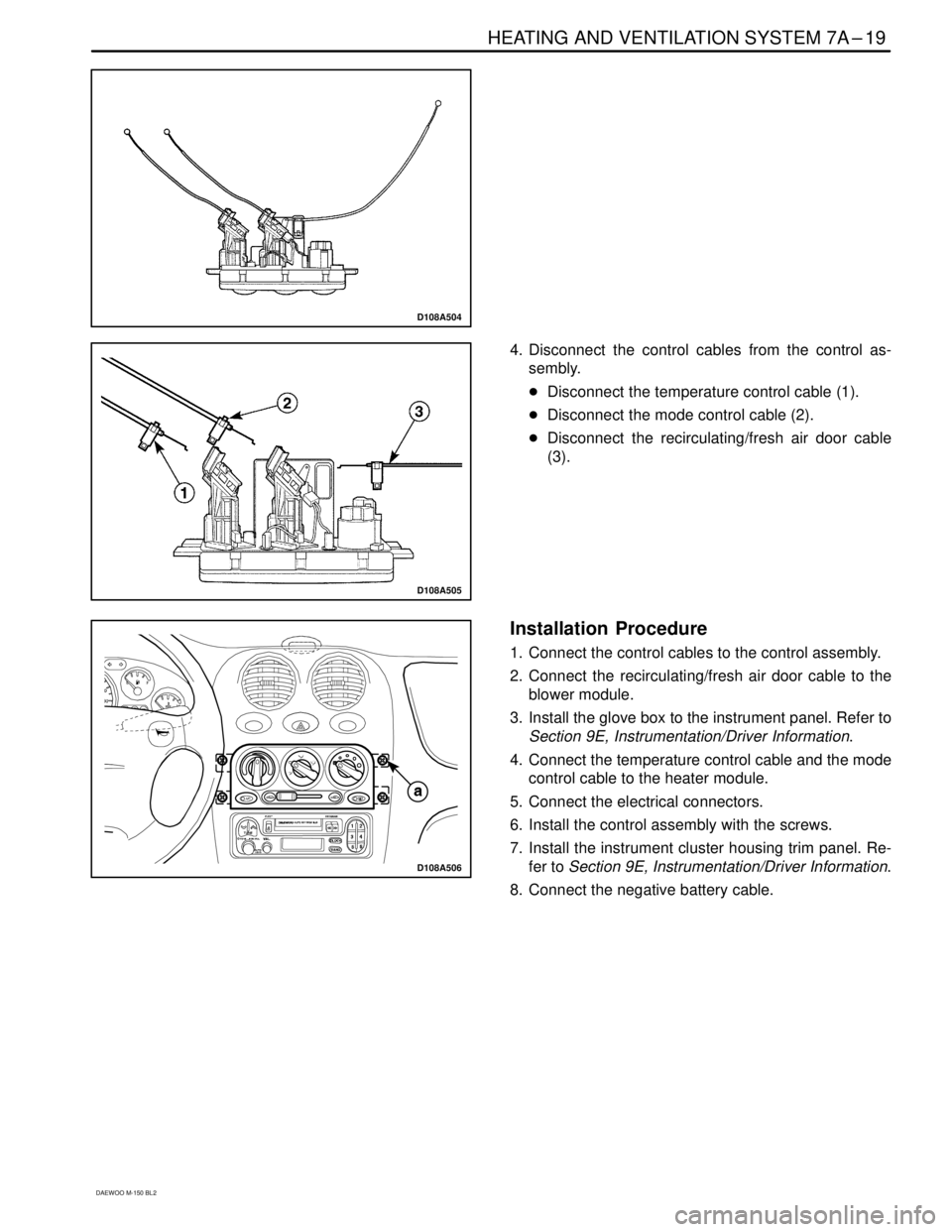
4. Disconnect the control cables from the control as-
sembly.
�Disconnect the temperature control cable (1).
�Disconnect the mode control cable (2).
�Disconnect the recirculating/fresh air door cable
(3).
D108A506
Installation Procedure
1. Connect the control cables to the control assembly.
2. Connect the recirculating/fresh air door cable to the
blower module.
3. Install the glove box to the instrument panel. Refer to
Section 9E, Instrumentation/Driver Information.
4. Connect the temperature control cable and the mode
control cable to the heater module.
5. Connect the electrical connectors.
6. Install the control assembly with the screws.
7. Install the instrument cluster housing trim panel. Re-
fer to Section 9E, Instrumentation/Driver Information.
8. Connect the negative battery cable.
Page 775 of 1184

HEATING AND VENTILATION SYSTEM 7A–25
DAEWOO M-150 BL2
D18A527B
D18A528B
Installation Procedure
1. Install the heater module with the nuts.
Tighten
Tighten the heater module lower nuts to 3–5 N�m
(27–44 lb-in) (1).
Tighten the heater module upper nuts to 3–5 N�m
(27–44 lb-in) (2).
2. Install the evaporator on the vehicle equipped with
A/C. Refer to Section 7B, Manual Control Heating,
Ventilation, and Air Conditioning System.
3. Install the heater module–to–blower module connec-
tion tube on the vehicle not equipped with A/C with
the screw.
4. Install the instrument panel and the lower tie bar. Re-
fer to Section 9E, Instrumentation/Driver Information.
5. Connect the heater hoses to the heater module. Re-
fer to “Heater Hoses” in this section.
D108A529
D108A530
BLOWER MODULE
(Left–Hand Drive Shown, Right–Hand
Drive Similar)
Removal Procedure
1. Remove the glove box from the instrument panel. Re-
fer to Section 9E, Instrumentation/Driver Information.
2. Remove the heater module–to–blower module con-
nection tube on the vehicle not equipped with A/C.
Refer to “Heater Module” in this section.
3. Remove the evaporator on the vehicle equipped with
A/C. Refer to Section 7B, Manual Control Heating,
Ventilation, and Air Conditioning System.
4. Remove the blower resistor. Refer to “Blower Resis-
tor” in this section.
5. Disconnect the blower motor connector. Refer to
“Blower Motor and Cooling Hose” in this section.
6. Remove the blower module.
�Remove the nuts (1).
�Disconnect the wiring harness (2).
Page 776 of 1184

7A–26 HEATING AND VENTILATION SYSTEM
DAEWOO M-150 BL2
D18A531B
Installation Procedure
1. Install the blower module with the nuts.
Tighten
Tighten the blower module retaining nuts to 3–5 N�m
(27–44 lb-in).
2. Connect the wiring harness.
3. Connect the blower motor connector. Refer to “Blow-
er Motor and Cooling Hose” in this section.
4. Install the blower resistor. Refer to “Blower Resistor”
in this section.
5. Install the evaporator on the vehicle equipped with
A/C. Refer to Section 7B, Manual Control Heating,
Ventilation, and Air Conditioning System.
6. Install the heater module–to–blower module connec-
tion tube on the vehicle not equipped with A/C. Refer
to “Heater Module” in this section.
7. Install the glove box to the instrument panel. Refer to
Section 9E, Instrumentation/Driver Information.
D108A532
DEFROSTER DUCT AND HOSES
(Left–Hand Drive Shown, Right–Hand
Drive Similar)
Removal Procedure
1. Remove the instrument panel. Refer to Section 9E,
Instrumentation/Driver Information.
2. Remove the defroster duct and hoses retaining
screws.
a. Retaining screw.
3. Remove the defroster duct and hoses.
b. Defroster duct and hoses.
D108A533
Installation Procedure
1. Install the defroster duct and hoses with the screws.
2. Install the instrument panel. Refer to Section 9E, In-
strumentation/Driver Information.
Page 808 of 1184
 (2).
DTighten the bolt securing the A/C low pr")
7B -- 26 MANUAL CONTROL HEATING, VENTILATION, AND AIR CONDITIONING SYSTEM
DAEWOO M-150 BL2
D18B530B
D18B531A
DTighten the bracket nut to 5 NSm (44 lb-in) (2).
DTighten the bolt securing the A/C low pressure pipe
line at the compressor to 23 NSm (17 lb-ft) (3).
2. Evacuate and recharge the system. Refer to “Dis-
charging, Adding Oil, Evacuating, and Charging Pro-
cedure for A/C System” in this section.
3. Connect the negative battery cable.
D108B532
D108B533
EVAPORATOR UNIT AND DRAIN
HOSE
(Left -- Hand Drive Shown, Right -- Hand
Drive Similar)
Removal Procedure
1. Disconnect the negative battery cable.
2. Discharge and recover the refrigerant. Refer to “Dis-
charging, Adding Oil, Evacuating, and Charging Pro-
cedures for A/C System” in this section.
3. Loosen the high pressure pipe line (receiver dry-
er→evaporator) nut and the low pressure pipe line
(evaporator→compressor) nut.
4. Remove the glove box. Refer toSection 9E, Instru-
mentation/Driver information.
5. Remove the evaporator unit.
DRemove the drain hose (1).
DDisconnect the thermistor connector (2).
DRemove the screws (3).
DRemove the evaporator backward slowly (4).
Page 809 of 1184
MANUAL CONTROL HEATING, VENTILATION, AND AIR CONDITIONING SYSTEM 7B -- 27
DAEWOO M-150 BL2
D18B534A
Installation Procedure
1. Install the evaporator evaporator with the screws.
2. Connect the thermistor connector.
3. Install the drain hose.
4. Install the glove box. Refer toSection 9E, Instrumen-
tation / Driver Information.
5. Tighten the high pressure pipe line (receiver dry-
er→evaporator) nut and the low pressure pipe line
(evaporator→compressor) nut to 14 NSm (10.5 lb-ft).
6. Evacuate and recharge the system. Refer to “Dis-
charging, Adding Oil, Evacuating, and Charging Pro-
cedures for A/C System” in this section.
7. Connect the negative battery cable.
Page 898 of 1184
 8B–71
DAEWOO M-150 BL2
5. Properly align the pointed marks () on the com-
ponents of the clock spring.
6. Connect the electrical connectors on the lower
spr")
SUPPLEMENTAL INFLATABLE RESTRAINTS (SIR) 8B–71
DAEWOO M-150 BL2
5. Properly align the pointed marks () on the com-
ponents of the clock spring.
6. Connect the electrical connectors on the lower
spring steering column.
7. Install the lower/upper steering column cover.
8. Install the steering wheel. Refer to Section 6E,
Steering Wheel and Column.
9. Connect the driver airbag module and the horn con-
nectors.
10. Install the driver airbag module. Refer to “Driver air-
bag module” in this section.
11. Connect the negative battery cable.
D110B508
PASSENGER AIRBAG MODULE
(Left–Hand Drive Shown, Right–Hand
Drive Similar)
Tool Required
DS 401 Torx Bolt Wrench.
Removal Procedure
1. Disconnect the negative battery cable.
2. Remove the glove box. Refer to Section 9E, Instru-
ment/Driver Information.
3. Disconnect the passenger airbag module connector.
D110B509
4. Remove the passenger airbag module.
�Remove the nuts (1).
�Remove the airbag module torx bolts using a torx
bolt wrench DS 401.
a. Passenger airbag module torx bolt.
�Remove the passenger airbag module (2).
15 N�m 10 N�m
D1AB510A
Installation Procedure
1. Install the passenger airbag module.
2. Install the passenger airbag module mounting torx
bolts and the nuts using a torx bolt wrench DS 401.
Tighten
�Tighten the passenger airbag module torx bolts to
15 N�m (11 lb-ft).
a. Passenger airbag module torx bolt.
�Tighten the passenger airbag module nuts to 10
N�m (89 lb-in).
b. Passenger airbag module nut.
Notice : Do not reuse the removed torx bolts.
Replace the torx bolts with the new ones.