Page 771 of 1184
HEATING AND VENTILATION SYSTEM 7A–21
DAEWOO M-150 BL2
D108A511
Installation Procedure
1. Install the blower resistor with the retaining screws.
2. Connect the blower resistor connector.
D108A512
BLOWER MOTOR SWITCH
(Left–Hand Drive Shown, Right–Hand
Drive Similar)
Removal Procedure
1. Remove the control assembly. Refer to “Control As-
sembly and Control Cables” in this section.
2. Remove the blower motor switch.
�Remove the switch knob (1).
D108A513
�Remove the blower motor switch retaining screw
(2).
�Turn the blower motor switch anticlockwise (3).
D108A514
Installation Procedure
1. Install the blower motor switch with the screw.
2. Install the switch knob.
3. Install the control assembly. Refer to “Control Assem-
bly and Control Cables” in this section.
Page 772 of 1184
7A–22 HEATING AND VENTILATION SYSTEM
DAEWOO M-150 BL2
D18A515A
HEATER HOSES
(Left–Hand Drive Shown, Right–Hand
Drive Similar)
Tool Required
DW100–020 Hose Remover/Installer.
Removal Procedure
1. Disconnect the negative battery cable.
2. Drain the coolant.
3. Remove the heater inlet hoses.
�Remove the air cleaner housing.
�Raise and suitably support the vehicle.
�Disconnect the hose from the heater module using
a hose remover DW100–020 (1).
D108A516
�Lower the vehicle.
�Disconnect the hose from the thermostat (2).
D18A517A
4. Remove the heater outlet hoses.
�Raise and suitably support the vehicle.
�Disconnect the hose from the heater module using
a hose remover DW100–020 (1).
�Disconnect the B
+ terminal from the starter. Refer
to Section 1E, Engine Electrical.
D108A518
�Disconnect the heater hose from the engine (2).
Page 773 of 1184
HEATING AND VENTILATION SYSTEM 7A–23
DAEWOO M-150 BL2
D108A521
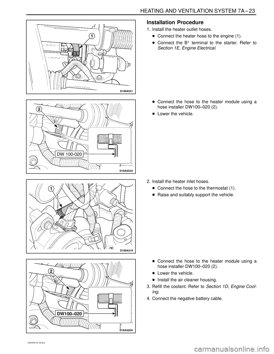
Installation Procedure
1. Install the heater outlet hoses.
�Connect the heater hose to the engine (1).
�Connect the B
+ terminal to the starter. Refer to
Section 1E, Engine Electrical.
D18A522A
�Connect the hose to the heater module using a
hose installer DW100–020 (2).
�Lower the vehicle.
D108A519
2. Install the heater inlet hoses.
�Connect the hose to the thermostat (1).
�Raise and suitably support the vehicle.
DW100–020
D18A520A
�Connect the hose to the heater module using a
hose installer DW100–020 (2).
�Lower the vehicle.
�Install the air cleaner housing.
3. Refill the coolant. Refer to Section 1D, Engine Cool-
ing.
4. Connect the negative battery cable.
Page 774 of 1184
7A–24 HEATING AND VENTILATION SYSTEM
DAEWOO M-150 BL2
D108A523
HEATER MODULE
(Left–Hand Drive Shown, Right–Hand
Drive Similar)
Removal Procedure
1. Disconnect the heater hoses from the heater module.
Refer to “Heater Hoses” in this section.
2. Remove the instrument panel and the lower tie bar
center. Refer to Section 9E, Instrumentation/Driver
Information.
3. Remove the heater module–to–blower module con-
nection tube on the vehicle not equipped with A/C.
a. Heater module–to–blower module connection tube.
D108A524
4. Remove the evaporator on the vehicle equipped with
A/C. Refer to Section 7B, Manual Control Heating,
Ventilation, and Air Conditioning System.
D108A525
5. Remove the heater module.
�Remove the upper nuts (1).
D108A526
�Remove the lower nuts (2).
�Remove the heater module (3).
Page 775 of 1184

HEATING AND VENTILATION SYSTEM 7A–25
DAEWOO M-150 BL2
D18A527B
D18A528B
Installation Procedure
1. Install the heater module with the nuts.
Tighten
Tighten the heater module lower nuts to 3–5 N�m
(27–44 lb-in) (1).
Tighten the heater module upper nuts to 3–5 N�m
(27–44 lb-in) (2).
2. Install the evaporator on the vehicle equipped with
A/C. Refer to Section 7B, Manual Control Heating,
Ventilation, and Air Conditioning System.
3. Install the heater module–to–blower module connec-
tion tube on the vehicle not equipped with A/C with
the screw.
4. Install the instrument panel and the lower tie bar. Re-
fer to Section 9E, Instrumentation/Driver Information.
5. Connect the heater hoses to the heater module. Re-
fer to “Heater Hoses” in this section.
D108A529
D108A530
BLOWER MODULE
(Left–Hand Drive Shown, Right–Hand
Drive Similar)
Removal Procedure
1. Remove the glove box from the instrument panel. Re-
fer to Section 9E, Instrumentation/Driver Information.
2. Remove the heater module–to–blower module con-
nection tube on the vehicle not equipped with A/C.
Refer to “Heater Module” in this section.
3. Remove the evaporator on the vehicle equipped with
A/C. Refer to Section 7B, Manual Control Heating,
Ventilation, and Air Conditioning System.
4. Remove the blower resistor. Refer to “Blower Resis-
tor” in this section.
5. Disconnect the blower motor connector. Refer to
“Blower Motor and Cooling Hose” in this section.
6. Remove the blower module.
�Remove the nuts (1).
�Disconnect the wiring harness (2).
Page 776 of 1184

7A–26 HEATING AND VENTILATION SYSTEM
DAEWOO M-150 BL2
D18A531B
Installation Procedure
1. Install the blower module with the nuts.
Tighten
Tighten the blower module retaining nuts to 3–5 N�m
(27–44 lb-in).
2. Connect the wiring harness.
3. Connect the blower motor connector. Refer to “Blow-
er Motor and Cooling Hose” in this section.
4. Install the blower resistor. Refer to “Blower Resistor”
in this section.
5. Install the evaporator on the vehicle equipped with
A/C. Refer to Section 7B, Manual Control Heating,
Ventilation, and Air Conditioning System.
6. Install the heater module–to–blower module connec-
tion tube on the vehicle not equipped with A/C. Refer
to “Heater Module” in this section.
7. Install the glove box to the instrument panel. Refer to
Section 9E, Instrumentation/Driver Information.
D108A532
DEFROSTER DUCT AND HOSES
(Left–Hand Drive Shown, Right–Hand
Drive Similar)
Removal Procedure
1. Remove the instrument panel. Refer to Section 9E,
Instrumentation/Driver Information.
2. Remove the defroster duct and hoses retaining
screws.
a. Retaining screw.
3. Remove the defroster duct and hoses.
b. Defroster duct and hoses.
D108A533
Installation Procedure
1. Install the defroster duct and hoses with the screws.
2. Install the instrument panel. Refer to Section 9E, In-
strumentation/Driver Information.
Page 777 of 1184
HEATING AND VENTILATION SYSTEM 7A–27
DAEWOO M-150 BL2
D18A534A
VENTILATION DUCT
(Left–Hand Drive Shown, Right–Hand
Drive Similar)
Removal Procedure
1. Remove the instrument panel. Refer to Section 9E,
Instrumentation/Driver Information.
2. Remove the ventilation duct retaining screws.
a. Retaining screw.
3. Remove the ventilation duct.
b. Ventilation duct.
D108A535
Installation Procedure
1. Install the ventilation duct with the screws.
2. Install the instrument panel. Refer to Section 9E, In-
strumentation/Driver Information.
Page 778 of 1184
7A–28 HEATING AND VENTILATION SYSTEM
DAEWOO M-150 BL2
UNIT REPAIR
D108A701
HEATER CORE
Disassembly Procedure
1. Remove the heater module. Refer to “Heater Module”
in this section.
2. Remove the heater core.
�Remove the heater core cover (1).
�Remove the heater core (2).
D108A702
Assembly Procedure
1. Install the heater core to the heater module.
2. Install the heater core cover.
3. Install the heater module. Refer to “Heater Module” in
this section.


Tool Required
DW100–020 Hose Remover/Installer.
Removal Procedure")

Removal Procedure
1. Disconnect the heater hoses from the heater m")

Removal Procedure
1. Remove the instrument panel. Refer to Sect")
