Page 76 of 1184
1E–20 ENGINE ELECTRICAL
DAEWOO M-150 BL2
D102E704
�Inspect the pinion gear’s moving to the outside (2).
�If the pinion gear does not move outside, replace
the magnetic switch.
D102E705
4. Solenoid hold-in test.
�Disconnect the starter motor terminal M (1).
�Connect the 12-volt battery lead to the starter mo-
tor terminal S and body.
Notice: Complete the testing in a minimum amount of
time to prevent overheating and damaging the solenoid.
D102E706
�Check the pinion gear’s moving to the outside (2).
�If the pinion gear move to the inside, the circuit is
open. Replace the magnetic switch.
D102E707
5. Solenoid return test.
�Disconnect the starter motor terminal M (1).
�Connect the 12-volt battery lead to the starter mo-
tor terminal S and body.
Notice: Complete the testing in a minimum amount of
time to prevent overheating and damaging the solenoid.
Page 77 of 1184
ENGINE ELECTRICAL 1E–21
DAEWOO M-150 BL2
D102E708
�Check the returning speed of pinion gear (2).
If the returning speed is fast, the operation is nor-
mal.
�Replace the solenoid if the operation is abnormal.
D102E709
5. No-road test.
�Connect the 12-volt battery lead to the starter cir-
cuit.
�Connect the current and the voltage (1).
�Install the starter motor rpm gage (2).
�Start the starter motor with the switch on (3).
�Measure the speed of pinion gear and the current.
�If the measurement satisfy the limit, the starter mo-
tor is normal.
D102E710
DesciptionLimit
The speed of pinion
gearMinimum: 2,000 rpm
Condition:
Voltage/CurrentMaximum: 9V / 150A
�Replace the starter motor if necessary.
D102E711
Disassembly Procedure
1. Remove the starter contact end frame.
�Remove the through-bolts (1).
�Remove the contact end frame bolts (2).
�Remove the frame with the spacer (3).
Page 78 of 1184
1E–22 ENGINE ELECTRICAL
DAEWOO M-150 BL2
D102E712
2. Remove the brush holder assembly.
�Remove the starter motor terminal M nut (1).
�Remove the brush holder assembly (2).
D102E713
3. Remove the field frame assembly from the armature
set (1).
D102E714
4. Remove the solenoid assembly.
�Remove the solenoid screws (1).
�Remove the magnetic switch (2).
�Remove the spring (3).
D102E715
5. Remove the armature set and solenoid from the start-
er housing.
�Remove the armature set (1).
�Remove the rubber sealer (2).
�Remove the shift lever plate (3).
�Remove the shift lever (4).
�Remove the solenoid (5).
�Remove the gasket (6).
Page 80 of 1184
1E–24 ENGINE ELECTRICAL
DAEWOO M-150 BL2
D12E720A
9-12 N�m
4-6 N�m
Assembly Procedure
1. Install in the reverse order of removal.
2. Install the bolts / nuts.
Tighten
Tighten the starter motor terminal M nut to 9–12 N�m
(80–106 lb-in) (a).
Tighten the through-bolts to 4–6 N�m (35–53 lb-in)
(b).
D102E721
GENERATOR (A-TYPE : MANDO)
Disassembly Procedure
1. Remove the generator. Refer to “Generator” in this
section.
2. Remove the front bracket and rear bracket.
�Remove the through-bolts (1).
D102E722
�Pry front bracket downwards using a screwdriver
(2).
�Separate the front bracket and rear bracket (3).
D102E723
3. Remove the pulley and rotor assembly from the front
bracket.
�Cover the rotor with the cloth (1).
�Place the pulley upwards and vice the rotor (2).
�Remove the pulley nut (3).
�Remove the pulley (4).
Page 83 of 1184
ENGINE ELECTRICAL 1E–27
DAEWOO M-150 BL2
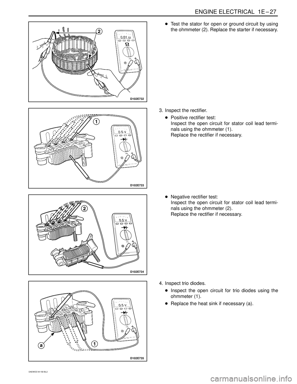
D102E732
�Test the stator for open or ground circuit by using
the ohmmeter (2). Replace the starter if necessary.
D102E733
3. Inspect the rectifier.
�Positive rectifier test:
Inspect the open circuit for stator coil lead termi-
nals using the ohmmeter (1).
Replace the rectifier if necessary.
D102E734
�Negative rectifier test:
Inspect the open circuit for stator coil lead termi-
nals using the ohmmeter (2).
Replace the rectifier if necessary.
D102E735
4. Inspect trio diodes.
�Inspect the open circuit for trio diodes using the
ohmmeter (1).
�Replace the heat sink if necessary (a).
Page 97 of 1184
kW0.8–
No Load Test @ 9 volts
D")
ENGINE ELECTRICAL 1E–41
DAEWOO M-150 BL2
SPECIFICATIONS
STARTER SPECIFICATIONS
ApplicationDescriptionUnitStandardLimit
Starter MotorType–SD 80–
Output(Capacity)kW0.8–
No Load Test @ 9 volts
Drive Pinion SpeedA
RPM150
2,000–
Brushes Lengthmm (in.)11.3–11.5
(0.445–0.453)7.0–7.25
(0.275–0.285)
GENERATOR SPECIFICATIONS
ApplicationDescriptionUnitStandardLimit
GeneratorTypeA-Type–J114D(MANDO)–GeneratorTypeA-Type
B-Type–J114D(MANDO)
CS114D(DAC)–
RegulatorA-TypeV14.4–15.0–Regulator
VoltageA-Type
B-TypeV14.4–15.0
14.3–4.9–
Brushes
LengthA-Type
B-Typemm (in.)18.5 (0.728)
20.0 (0.787)13.5 (0.531)
14 (0.551)
OutputA-Type–12V, 65A–Output
(Capacity)A-Type
B-Type–12V, 65A
12V, 65A–
IGNITION SYSTEM SPECIFICATIONS
ApplicationDescriptionUnitStandardLimit
Ignition CoilType–Closed
Magnetic Type–
First Coil ResistanceΩ1.2�10%–
Second Coil ResistanceKΩ12.1 �15%–
DistributorType–Optical Sensor
Type–
Spark PlugTypeUnlead–BPR5EY-11–
RN9YC4–
WR8DCX–
TypeLead–BPR5EY–
RN9YC–
WR8DC–
Spark PlugGapUnleadmm (in.)1.1 (0.043)–
1.2 (0.047)–
Leadmm (in.)0.8 (0.031)–
Ignition WireIgnition Wire ResistanceKΩ/m2.5–12.0–
Page 98 of 1184

1E–42 ENGINE ELECTRICAL
DAEWOO M-150 BL2
BATTERY SPECIFICATIONS
ApplicationDescriptionUnitStandardLimit
BatteryType–MF–
CapacityAH35–
Cold Cranking AmpsCCA246–
FASTENER TIGHTENING SPECIFICATIONS
ApplicationN�mLb-FtLb-In
Distributor Bolts10–16–89–142
Battery Retainer Clamp–to–Battery Rod Nuts6–8–53–71
Battery Carrier Tray Bolts9–12–80–106
Battery Cable Nuts9–12–80–106
Starter field Connector Nut9–12–80–106
Starter Through–Bolts4–6–35–53
Starter Mounting Bolts55–6541–48–
Starter Solenoid Assembly Screws6–8–53–71
Starter Solenoid Nuts9–12–80–106
Spark Plug20–3015–22–
Generator Through–Bolts4–6–35–53
Generator Drive End Nut80–11 059–81–
Generator Battery Lead Connector Nut4–7–35–62
Generator Bearing Plate Bolt6–8–53–71
Generator Brush Holder / Rectifier Screw9–12–80–106
Generator Belt Tension Adjusting Bolt18–2813–21–
Generator Shackle Bracket Bolt45–5533–41–
Generator Lower Bracket–to–Generator Bolt/Nut18–2813–21–
Ground Bolt35–4126–30–
Ignition Coil Screw4–7–35–62
Ignition Coil Bracket Bolt9–12–80–106
Page 413 of 1184

ENGINE CONTROLS 1F–315
DAEWOO M-150 BL2
Important: A special anti–seize compound is used on
the oxygen sensor threads. This compound consists of
a liquid graphite and glass beads. The graphite will burn
away, but the glass beads will remain, making the sen-
sor easier to remove. New or service sensors will al-
ready have the compound applied to the threads. If a
sensor is removed from any engine and if for any reason
it is to be reinstalled, the threads must have anti–seize
compound applied before reinstallation.
2. Install the oxygen sensor.
Tighten
Tighten the oxygen sensor to 35~44 N�m (26~33 lb-
ft).
MAA1F480
EXHAUST GAS RECIRCULATION
VA LV E
Removal Procedure
1. Disconnect the negative battery cable.
2. Remove the air cleaner assembly.
3. Disconnect the electric exhaust gas recirculation
(EEGR) valve connector.
D21F008
KNOCK SENSOR
Removal Procedure
1. Disconnect the negative battery cable.
2. Remove the starter. Refer to Section 1E, Engine
Electrical.
3. Disconnect the electrical connector at the knock sen-
sor (1).
D21F009
4. Remove the knock sensor.
�Remove the knock sensor retaining bolt (1).
�Remove the knock sensor.