Page 414 of 1184
.
2.")
1F–316 ENGINE CONTROLS
DAEWOO M-150 BL2
D21F010
Installation Procedure
1. Install the knock sensor with the bolt.
Tighten
Tighten the knock sensor retaining bolt to 15–25 N�m
(11–18 lb-ft).
2. Connect the electrical connector to the knock sensor.
3. Install the starter. Refer to Section 1E, Engine Electri-
cal.
4. Connect the negative battery cable.
MAA1F490
ELECTRONIC IGNITION (EI) SYSTEM
IGNITION COIL
Removal Procedure
1. Disconnect the negative battery cable.
2. Note the ignition wire location and disconnect the
ignition wires from the EI system ignition coil.
3. Disconnect the EI system ignition coil connector.
4. Remove the EI system ignition coil retaining bolts.
5. Remove the EI system ignition coil.
MAA1F500
Installation Procedure
1. Install the EI system ignition coil.
2. Tighten the EI system ignition coil to 8–12 N�m
(71–106 lb-in).
UAA1F2C0
CRANKSHAFT POSITION (CKP)
SENSOR
Removal Procedure
1. Disconnect the negative battery cable.
2. Remove the air cleaner assembly.
3. Disconnect the crankshaft position (CKP) sensor
connector.
4. Remove the CKP sensor retaining bolt.
Page 636 of 1184
FIVE-SPEED MANUAL TRANSAXLE 5B–11
DAEWOO M-150 BL2
D13B5031
6. Disconnect the radiator lower hose.
�Remove the bolts (1).
�Disconnect the radiator lower hose (2).
7. Remove crankshaft position (CKP) sensor.
�Remove the bolt (3).
�Disconnect the CKP sensor connector
�Remove the CKP sensor.
D103B507
8. Disconnect the speedometer cable.
�Loosen the nut (1).
�Disconnect the cable (2).
9. Remove the vehicle speed sensor (VSS) if
equipped.
�Disconnect VSS connector.
�Remove the VSS.
D102E502
10. Remove the starter motor.
�Remove upper two bolts that securing starter mo-
tor to transaxle.
D13B5041
11. Fix the engine assembly.
�Remove the cowl panel weatherstrip.
�Position the engine support fixture DW110–021
on the cowl panel and the front upper panel.
�Tighten the engine fixture joint with a bolt after re-
moving exhaust manifold bolt (No.4).
Page 640 of 1184
FIVE-SPEED MANUAL TRANSAXLE 5B–15
DAEWOO M-150 BL2
D13B518A
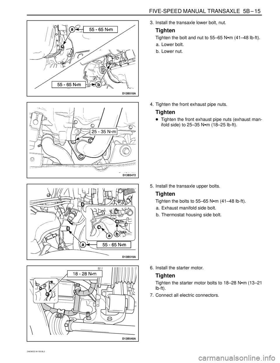
3. Install the transaxle lower bolt, nut.
Tighten
Tighten the bolt and nut to 55–65 N�m (41–48 lb-ft).
a. Lower bolt.
b. Lower nut.
D13B5472
4. Tighten the front exhaust pipe nuts.
Tighten
�Tighten the front exhaust pipe nuts (exhaust man-
ifold side) to 25–35 N�m (18–25 lb-ft).
D13B519A
5. Install the transaxle upper bolts.
Tighten
Tighten the bolts to 55–65 N�m (41–48 lb-ft).
a. Exhaust manifold side bolt.
b. Thermostat housing side bolt.
D13B548A
6. Install the starter motor.
Tighten
Tighten the starter motor bolts to 18–28 N�m (13–21
lb-ft).
7. Connect all electric connectors.
Page 678 of 1184

FIVE-SPEED MANUAL TRANSAXLE 5B–53
DAEWOO M-150 BL2
FASTENER TIGHTENING SPECIFICATIONS
ApplicationN�mLb-FtLb-In
5th/Reverse Gear Shift Shaft Bolt10 – 167 – 12–
Back Up Light Switch Nut15 – 1811 – 13–
Counter Shaft 5th Gear Nut60 – 8044 – 59–
Crankshaft Position Sensor Bolt5 – 8–44 – 70
Differential Ring Gear Bolt80 – 10059 – 74–
Engine Mounting Front Bracket Bolt
(Cylinder Block Side)35 – 4125 – 30–
Engine Mounting Front Damping Bush Bolt
(Crossmember Side)35 – 4125 – 30–
Engine Mounting Front Damping Bush Bolts
(Crossmember Side)45 – 5533 – 41–
Engine Mounting Front Damping Bush Bolt/Nut
(Bracket Side)68 – 8351 – 61–
Front Exhaust Pipe Nut
(Exhaust Manifold Side/Muffler Side)25 – 3518 – 25–
Gear Shift Control Case Bolt18 – 2813 – 21–
Gear Shift Lever Bolt4 – 7–35 – 62
High Speed Shift Shaft Bolt10 – 167 – 12–
Low Speed Shift Shaft Bolt10 – 167 – 12–
Oil Drain Plug25 – 3018 – 22–
Oil Level Plug36 – 5426 – 40–
Radiator Lower Hose Bracket Bolts8 – 15–70 – 132
Reverse Idle Gear Shaft Bolt18 – 2813 – 21–
Reverse Shift Lever Bolt18 – 2813 – 21–
Select Cable Nut(Shift Lever Side)8 – 12–71 – 106
Select Lever Bolt18 – 2813 – 21–
Side Cover Plate Screw6 – 7–53 – 62
Shift Guide Bolt18 – 2813 – 21–
Shift Interlock Bolt18 – 2813 – 21–
Side Cover Bolt8 – 12–71 – 106
Speedometer Driven Gear Bolt4 – 7–35 – 62
Starter Motor Bolt18 – 2813 – 21–
Transaxle Case Bolt15 – 2211 – 16–
Transaxle Case(left) Cap Bolt8 – 12–71 – 106
Transaxle Lower Bolt and Nut(Engine Side)55 – 6541 – 48–
Transaxle Mounting Bolt(Body Side)45 – 5533 – 41–
Transaxle Mounting Bolt and Nut(Transaxle Side)55 – 6541 – 48–
Transaxle Upper Bolt(Engine Side)55 – 6541 – 48–
Transaxle Under Cover Bolt35 – 5525 – 41–
Page 772 of 1184
7A–22 HEATING AND VENTILATION SYSTEM
DAEWOO M-150 BL2
D18A515A
HEATER HOSES
(Left–Hand Drive Shown, Right–Hand
Drive Similar)
Tool Required
DW100–020 Hose Remover/Installer.
Removal Procedure
1. Disconnect the negative battery cable.
2. Drain the coolant.
3. Remove the heater inlet hoses.
�Remove the air cleaner housing.
�Raise and suitably support the vehicle.
�Disconnect the hose from the heater module using
a hose remover DW100–020 (1).
D108A516
�Lower the vehicle.
�Disconnect the hose from the thermostat (2).
D18A517A
4. Remove the heater outlet hoses.
�Raise and suitably support the vehicle.
�Disconnect the hose from the heater module using
a hose remover DW100–020 (1).
�Disconnect the B
+ terminal from the starter. Refer
to Section 1E, Engine Electrical.
D108A518
�Disconnect the heater hose from the engine (2).
Page 773 of 1184
HEATING AND VENTILATION SYSTEM 7A–23
DAEWOO M-150 BL2
D108A521
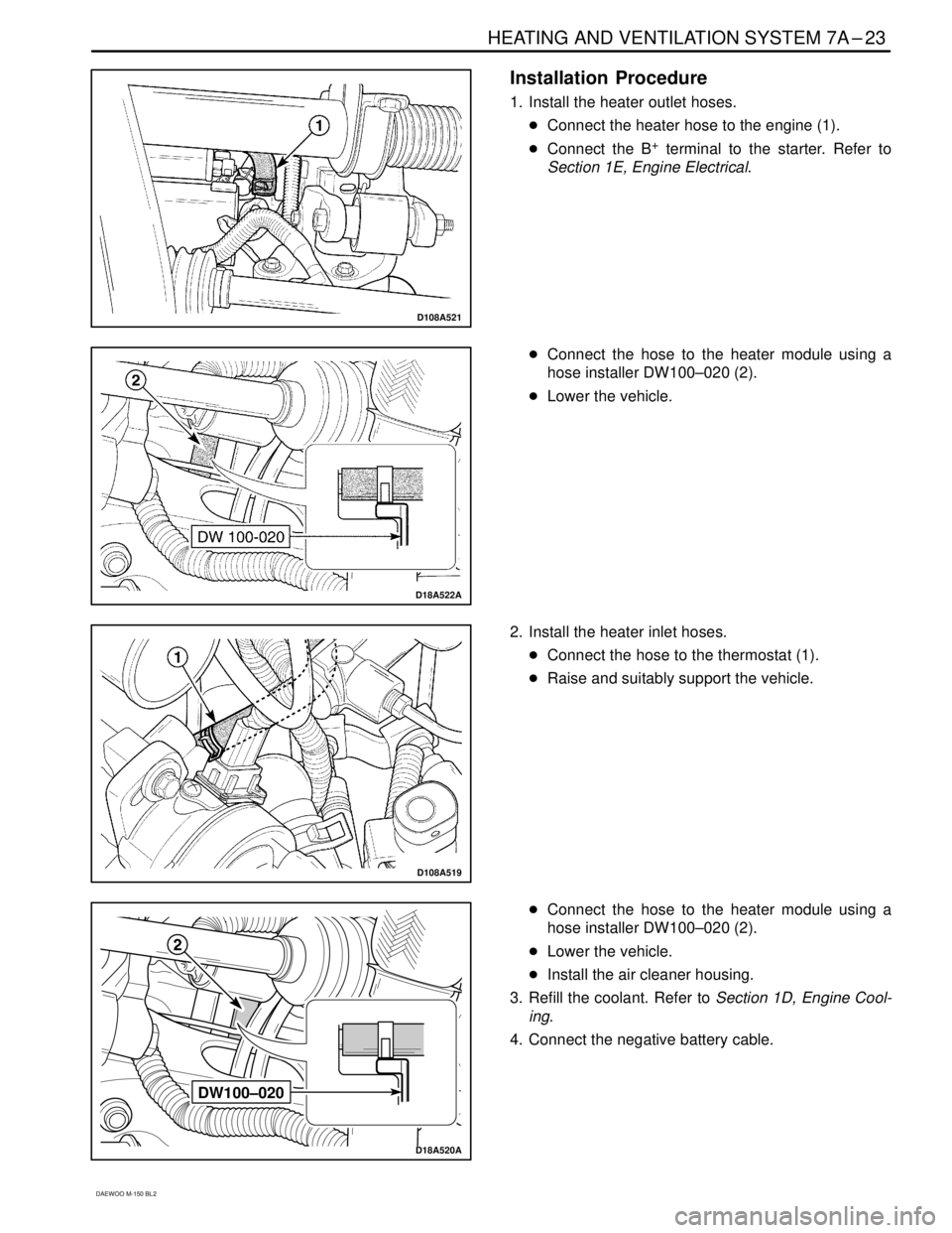
Installation Procedure
1. Install the heater outlet hoses.
�Connect the heater hose to the engine (1).
�Connect the B
+ terminal to the starter. Refer to
Section 1E, Engine Electrical.
D18A522A
�Connect the hose to the heater module using a
hose installer DW100–020 (2).
�Lower the vehicle.
D108A519
2. Install the heater inlet hoses.
�Connect the hose to the thermostat (1).
�Raise and suitably support the vehicle.
DW100–020
D18A520A
�Connect the hose to the heater module using a
hose installer DW100–020 (2).
�Lower the vehicle.
�Install the air cleaner housing.
3. Refill the coolant. Refer to Section 1D, Engine Cool-
ing.
4. Connect the negative battery cable.
Page 916 of 1184
50ABATABS
Ef240ABATIgnition Switch, Instrument Panel Fuse Block
(F5, F11 ~ F13)
Ef310ABATFuel cut-off")
9A–10 BODY WIRING SYSTEM
DAEWOO M-150 BL2
FUSE CHART
FuseRating/ SourceCircuit
Ef1 (Engine Fuse)50ABATABS
Ef240ABATIgnition Switch, Instrument Panel Fuse Block
(F5, F11 ~ F13)
Ef310ABATFuel cut-off Switch (Inertia Switch)
Ef410AIGN 1Fuel, EBCM, Generator, VSS, Fuel Pump Relay, Main Relay,
Ignition Coil
Ef5––Not Used
Ef620ABATBlower Motor
Ef715ABATRear Window Defogger
Ef810ABATHeadlamp Hi Beam, Right Side
Ef910ABATHeadlamp Hi Beam, Left Side
Ef1010ABATHeadlamp Lo Beam, Right Side
Ef1110ABATHeadlamp Lo Beam, Left Side
Ef1210A58Tail and Illumination Lamps, Right Side
Ef1310A58Tail and Illumination Lamps, Left Side
Ef1410ABATA/C Compressor
Ef1530ABATRadiator Fan
Ef1610A–Spare
Ef1710ABATHorn
Ef1820ABATHeadlamp Relay, Hi Beam Passing, DRL Module
Ef1915ABATECM, Main Relay
Ef2015ABATFront Fog Lamp
Ef2115A–Spare
F1 (Fuse)10AIGN 1Cluster, Clock, IMMO, Anti-Theft Control Unit,
DRL Relay
F210AIGN 1SDM
F325AIGN 1Hazard Switch, DRL Module
F410AIGN 1Turn Signal Lamp
F515ABATStop Lamp
F610AACCAudio
F720AACCCigar Light
F815AIGN 2Wiper
F915AIGN 2Rear Wiper Motor, Front & Rear Washer, Backup Lamp
F1010AIGN 2Auto Miror Switch
F1110AEf2IMMO, Audio, Room Lamp
F1215AEf2Hazard, Clock
F1320AEf2Anti-Theft Control Unit, Door Lock
F1420ASTStarter Motor
Page:
< prev 1-8 9-16 17-24


Tool Required
DW100–020 Hose Remover/Installer.
Removal Procedure")