Page 661 of 1184
.
Tighten
Tighten the n")
5B–36 FIVE-SPEED MANUAL TRANSAXLE
DAEWOO M-150 BL2
D13B744A
24. Install the backup light switch and the speedometer
driven gear assembly.
�Install the backup light switch (1).
Tighten
Tighten the nut to 15–18 N�m (11–13 lb-ft) (a).
�Install the speedometer driven gear assembly
(2).
Tighten
Tighten the bolt to 4–7 N�m (35–62 lb-in) (b).
�Install the hydraulic pump assembly (If equipped
with auto clutch). Refer to Section 5D, Auto
Clutch.
D13B7452
25. Install the transaxle mount.
�Install the mount (1).
Tighten
�Tighten the bolts to 55–65 N�m (41–48 lb-ft) (a).
�Tighten the nut to 55–65 N�m (41–48 lb-ft) (b).
D13B701A
26. Install the related clutch parts. Refer to Section 5C,
Clutch.
27. Remove the transaxle assembly from transaxle
stand.
�Remove the transaxle assembly using the trans-
axle fixture DW220–010A.
28. Install the transaxle assembly. Refer to “Manual
Transaxle Assembly” in this section.
D103B746
INPUT SHAFT
Tools Required
DW09921–57810 Gear, Bearing Remover
DW09925–98221 Gear, Bearing Installer
DW09940–53111 Gear, Bearing Installer
Disassembly Procedure
1. Remove the gear unit. Refer to “Gear Unit” in this
section.
2. Remove the input shaft right side bearing.
�Position the bearing to the gear, bearing remover
DW09921–57810.
�Remove the bearing by pressing (1).
Page 662 of 1184
FIVE-SPEED MANUAL TRANSAXLE 5B–37
DAEWOO M-150 BL2
D103B747
3. Remove the input shaft fifth gear spacer, the left side
bearing and the fourth gear.
�Position the fourth gear to the gear,bearing remov-
er DW09921–57810.
�Remove the following parts.
a. Fifth gear spacer.
b. Left side bearing.
c. Fourth gear
D103B748
4. Remove the fourth gear bearing.
5. Remove the fourth gear synchronizer ring and wave
spring.
D103B749
6. Remove the third–fourth synchronizer circlip.
D103B750
7. Remove the third–fourth synchronizer hub assembly,
the third gear 1 synchronizer ring.
�Position the third gear to the gear, bearing remover
DW09921–57810.
�Remove the following parts.
a. Third–fourth synchronizer hub assembly.
b. Third gear and synchronizer ring.
Page 665 of 1184

5B–40 FIVE-SPEED MANUAL TRANSAXLE
DAEWOO M-150 BL2
D103B759
2. Assemble the third–fourth synchronizer hub assem-
bly.
�Install the synchronizer springs to the hub.
�Install the synchronizer key to the hub.
Important: In case of assembling the synchronizer
sleeve and the hub, let A=B.
�Install the hub to the sleeve.
a. Sleeve.
b. Hub.
D103B760
3. Install the third–fourth synchronizer hub assembly.
�Insert the hub assembly into the input shaft (1).
Important: Position the longer flange of hub toward the
third gear and match the key and the ring groove.
�Install the hub assembly using a hammer and the
gear, bearing installer DW09940–53111.
D13B761A
Notice: When installing gear, bearing and hub assem-
bly, install them slowly using the gear, bearing installer
DW09940–53111 and a hammer. If overpressed, the
gear teeth may be damaged.
D103B749
4. Install the third–fourth synchronizer circlip.
5. Install the fourth synchronizer ring and wave spring.
Important: Match the ring groove to the key of hub.
Page 667 of 1184
5B–42 FIVE-SPEED MANUAL TRANSAXLE
DAEWOO M-150 BL2
Disassembly Procedure
1. Remove the gear unit. Refer to “Gear Unit” in this
section.
2. Remove the counter shaft right side bearing.
D103B766
3. Remove the counter shaft left side bearing and the
fourth gear.
�Position the fourth gear to the gear, bearing remov-
er DW09921–57810.
�Remove the following parts by pressing.
a. Counter shaft left side bearing.
b. Fourth gear.
D103B767
4. Remove the counter shaft third–fourth gear spacer.
5. Remove the counter shaft third gear and second gear.
�Position the second gear to the gear, bearing re-
mover DW09921–57810.
�Remove the following parts by pressing
a. Third gear.
b. Second gear.
D103B768
6. Remove the counter shaft second gear bearing.
7. Remove the second gear synchronizer ring.
8. Remove the first–second gear synchronizer circlip.
Page 668 of 1184
FIVE-SPEED MANUAL TRANSAXLE 5B–43
DAEWOO M-150 BL2
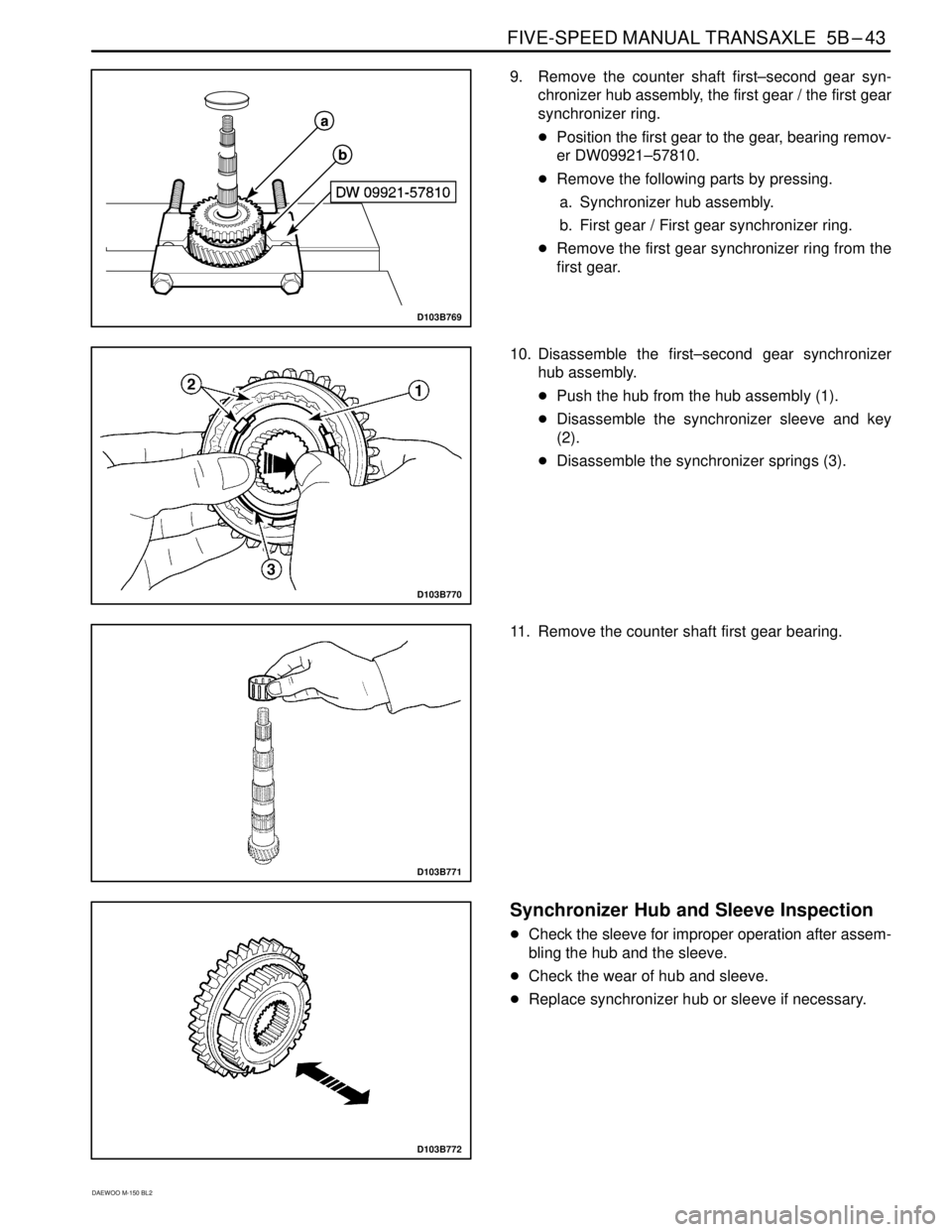
D103B769
9. Remove the counter shaft first–second gear syn-
chronizer hub assembly, the first gear / the first gear
synchronizer ring.
�Position the first gear to the gear, bearing remov-
er DW09921–57810.
�Remove the following parts by pressing.
a. Synchronizer hub assembly.
b. First gear / First gear synchronizer ring.
�Remove the first gear synchronizer ring from the
first gear.
D103B770
10. Disassemble the first–second gear synchronizer
hub assembly.
�Push the hub from the hub assembly (1).
�Disassemble the synchronizer sleeve and key
(2).
�Disassemble the synchronizer springs (3).
D103B771
11. Remove the counter shaft first gear bearing.
D103B772
Synchronizer Hub and Sleeve Inspection
�Check the sleeve for improper operation after assem-
bling the hub and the sleeve.
�Check the wear of hub and sleeve.
�Replace synchronizer hub or sleeve if necessary.
Page 669 of 1184
.
�Install the first gear (2).
�In")
5B–44 FIVE-SPEED MANUAL TRANSAXLE
DAEWOO M-150 BL2
D103B773
Assembly Procedure
1. Install the related counter shaft first gear.
�Install the first gear bearing (1).
�Install the first gear (2).
�Install the first gear synchronizer ring (3)
Important: Coat the inner parts; gear, bearing and oil
seal etc. with gear fluid.
Important: Be careful there is the difference of key
groove width between the first synchronizer ring and the
second synchronizer ring.
D103B774A
Unit : mm (in.)
��������� �
��������
��������� �
��������
First synchronizer ring (A)
: 8.2 (0.323)
��������� �
�������� ���������
Key Groove Width��������� �
�������� ���������Second synchronizer ring
(B) : 9.6 (0.378)
D103B775
2. Assemble the first–second synchronizer hub assem-
bly.
�Install the synchronizer springs to hub.
�Install the synchronizer keys to hub.
Important: Let (A)=(B) when installing the keys.
�Install the hub to the sleeve.
a. Sleeve.
b. Hub.
D103B776
3. Install the first–second synchronizer hub assembly.
�Insert the hub assembly into the counter shaft us-
ing the gear, bearing installer DW09940–53111,
the gear bearing remover/installer KM466–A and a
hammer (1).
Important: Position the synchronizer key to the first
gear synchronizer ring groove.
Page 670 of 1184
FIVE-SPEED MANUAL TRANSAXLE 5B–45
DAEWOO M-150 BL2
D103B768
4. Install the second synchronizer ring.
Important: Position the second synchronizer ring groove
to the synchronizer hub key.
5. Install the first–second gear synchronizer circlip.
D103B777
6. Install the related counter shaft second gear.
�Install the second gear bearing (1).
�Install the second gear (2).
D103B778
7. Install the counter shaft third gear and the third–fourth
gear spacer.
�Insert the third gear and the third–fourth gear
spacer into the counter shaft.
�Install the following parts using the gear, bearing
installer DW09913–80112 and a hammer.
a. Third–fourth gear spacer.
b. Third gear.
D103B779
8. Install the counter shaft fourth gear.
�Install the fourth gear to the counter shaft using the
gear, bearing installer DW09925–98221 and a
hammer (1).
Page 678 of 1184

FIVE-SPEED MANUAL TRANSAXLE 5B–53
DAEWOO M-150 BL2
FASTENER TIGHTENING SPECIFICATIONS
ApplicationN�mLb-FtLb-In
5th/Reverse Gear Shift Shaft Bolt10 – 167 – 12–
Back Up Light Switch Nut15 – 1811 – 13–
Counter Shaft 5th Gear Nut60 – 8044 – 59–
Crankshaft Position Sensor Bolt5 – 8–44 – 70
Differential Ring Gear Bolt80 – 10059 – 74–
Engine Mounting Front Bracket Bolt
(Cylinder Block Side)35 – 4125 – 30–
Engine Mounting Front Damping Bush Bolt
(Crossmember Side)35 – 4125 – 30–
Engine Mounting Front Damping Bush Bolts
(Crossmember Side)45 – 5533 – 41–
Engine Mounting Front Damping Bush Bolt/Nut
(Bracket Side)68 – 8351 – 61–
Front Exhaust Pipe Nut
(Exhaust Manifold Side/Muffler Side)25 – 3518 – 25–
Gear Shift Control Case Bolt18 – 2813 – 21–
Gear Shift Lever Bolt4 – 7–35 – 62
High Speed Shift Shaft Bolt10 – 167 – 12–
Low Speed Shift Shaft Bolt10 – 167 – 12–
Oil Drain Plug25 – 3018 – 22–
Oil Level Plug36 – 5426 – 40–
Radiator Lower Hose Bracket Bolts8 – 15–70 – 132
Reverse Idle Gear Shaft Bolt18 – 2813 – 21–
Reverse Shift Lever Bolt18 – 2813 – 21–
Select Cable Nut(Shift Lever Side)8 – 12–71 – 106
Select Lever Bolt18 – 2813 – 21–
Side Cover Plate Screw6 – 7–53 – 62
Shift Guide Bolt18 – 2813 – 21–
Shift Interlock Bolt18 – 2813 – 21–
Side Cover Bolt8 – 12–71 – 106
Speedometer Driven Gear Bolt4 – 7–35 – 62
Starter Motor Bolt18 – 2813 – 21–
Transaxle Case Bolt15 – 2211 – 16–
Transaxle Case(left) Cap Bolt8 – 12–71 – 106
Transaxle Lower Bolt and Nut(Engine Side)55 – 6541 – 48–
Transaxle Mounting Bolt(Body Side)45 – 5533 – 41–
Transaxle Mounting Bolt and Nut(Transaxle Side)55 – 6541 – 48–
Transaxle Upper Bolt(Engine Side)55 – 6541 – 48–
Transaxle Under Cover Bolt35 – 5525 – 41–