Page 618 of 1184
4G – 2 PARKING BRAKE
DAEWOO M-150 BL2
DESCRIPTION AND OPERATION
PARKING BRAKE
This braking system uses a BRAKE warning light lo-
cated in the instrument panel cluster. When the ignition
switch is in the III position, the BRAKE warning light
should glow and go OFF when the parking brake lever is
released. Whenever the parking brake is applied and theignition switch is II, the BRAKE warning light should
glow.
When the brake is firmly applied, the parking brake
should securely hold the vehicle with ample pedal travel
remaining. Check for frayed cables, rust, etc., or any
condition that may inhibit present (or future) free move-
ment of the parking brake lever assembly.
Page 632 of 1184
FIVE-SPEED MANUAL TRANSAXLE 5B–7
DAEWOO M-150 BL2
DIFFERENTIAL AND CASE
D13B4041
1 Speedometer Driven Gear
2 Oil Level Plug
3 Case Cap O–ring(Left)
4 Case Cap(Left)
5 Back Up Light Switch
6 Transaxle Case(Right)
7 Oil Plate
8 Transaxle Case(Left)
9 Oil Drain Plug
10 Oil Gutter
11 Side Cover Plate
12 Side Cover
13 Differential Ring Gear14 Differential Oil Seal(Left)
15 Differential Bearing(Left)
16 Differential Case
17 Speedometer Drive Gear
18 Differential Bearing(Right)
19 Differential Oil Seal(Right)
20 Differential Pinion Gear Shaft Pin
21 Differential Side Gear Adjust Shim
22 Differential Side Gear
23 Differential Pinion Gear Shaft
24 Differential Pinion Gear
25 Differential Pinion Gear Washer
Page 634 of 1184

FIVE-SPEED MANUAL TRANSAXLE 5B–9
DAEWOO M-150 BL2
CHECKING FLUID LEVEL
Check for a leak in the area of transaxle case and seal-
ing and then check fluid level and condition after remov-
ing oil level plug.
1. Operate the engine until it comes to normal operating
temperature(Coolant temperature : 80~90°C (176~
194°F)).
2. Stall the engine and raise the vehicle.
3. Remove the oil level plug and check the fluid level.
4. The fluid should slightly flow out from the oil level plug
hole.
5. If the level is low, add the recommended fluid through
the oil level plug hole until the fluid begins to run out.
6. If the fluid is contaminated or discolored, replace it
with the recommended fluid.
7. Reinstall the oil level plug and tighten it securely.
D103B301
CHANGING FLUID
1. Operate the engine until it comes to normal operating
temperature(Coolant temperature : 80~90°C (176~
194°F)).
2. Stall the engine and raise the vehicle.
3. Drain the fluid after removing the drain plug.
4. Reinstall the drain plug and tighten it securely after
coating sealant.
5. Remove the oil level plug and replenish the fluid until
it begins to run out.
a. Oil drain plug.
b. Oil level plug.
6. Reinstall the oil level plug and tighten it securely.Fluid Specification
75W-85(GL-4)
Fluid Capacity2.1L(2.21qt)
Service intervalRefer to Owner’s Manual
CHECKING TRANSAXLE NOISE
Many noises that appear to come from the transaxle
may actually originate with other sources such as tires,
road surfaces, wheel bearings, or engine and exhaust
system.
Identify the cause of any noise before attempting to re-
pair the clutch, the transaxle, or their related linkages.
To verify suspected transaxle noises,
1. Select a smooth, level asphalt road to reduce tyre
and resonant body noise.
2. Drive the vehicle far enough to warm up all the lubri-
cants thoroughly.
3. Record the speed and the gear range of the transaxle
when the noise occurs.
4. Check for noises with the vehicle stopped, but with
the engine running.
5. Determine if the noise occurs while the vehicle oper-
ates in.
�Drive – Under a light acceleration or a heavy pull.
�Float – Maintaining a constant speed with a light
throttle on a level road.
�Coast – With the transaxle in gear and the throttle
partly or fully closed.
�All of the above.
CHECKING BEARING NOISE
Differential Side Bearing Noise
Differential side bearing noise and wheel bearing noise
can be confused easily. Since side bearings are pre-
loaded, a differential side bearing noise should not di-
minish much when the differential/transaxle is run with
the wheels off the ground.
Wheel Bearing Noise
Wheel bearings produce a rough growl or grating sound
that will continue when the vehicle is coasting and the
transaxle is in NEUTRAL. Since wheel bearings are not
pre-loaded, a wheel bearing noise should diminish con-
siderably when the wheels are off the ground.
Page 647 of 1184

5B–22 FIVE-SPEED MANUAL TRANSAXLE
DAEWOO M-150 BL2
D103B540
Installation Procedure
1. Install in the reverse order of removal.
2. Push the cables toward the engine compartment
through dash panel’s hole slightly.
3. Position the cables on the select and the shift lever.
D13B5411
4. Connect the transaxle side select and shift control
cable.
5. Connect the gear shift lever side shift control cable.
6. Connect the gear shift lever side select control cable.
�Insert the select control cable eye ring to the select
arm pin (1).
�Install the selector lever control cable clip (2).
�Install the select control cable to gear shift lever
bracket with E–ring (3).
�Insert a driver to the select arm adjustment hole to
prevent the movement of gear shift lever in NEU-
TRAL (4).
7. Tighten the adjust nuts.
Tighten
Tighten the select cable adjust nut to 8–12 N�m
(71–106 lb-in).
D103B543
GEAR SHIFT CONTROL LEVER
Removal Procedure
1. Remove the floor console. Refer to Section 9G, Inte-
rior Trim.
2. Disconnect the select and shift control cable. Refer to
“Gear Shift control cable” in this section.
3. Remove the gear shift control lever assembly.
�Remove the bolts (1).
�Remove the gear shift control lever assembly (2).
�Remove the gear shift lever sensor connector.
(If equipped with auto clutch).
Page 649 of 1184
5B–24 FIVE-SPEED MANUAL TRANSAXLE
DAEWOO M-150 BL2
MAINTENANCE AND REPAIR
UNIT REPAIR
D13B701A
GEAR UNIT
Tools Required
09913–76010 Bushing, Seal Installer
DW09940–53111 Gear, Bearing Installer
DW09943–78210 Bushing, Seal Installer
DW220–010A Transaxle Fixture
KM519 Oil Seal Installer
Disassembly Procedure
1. Remove the manual transaxle. Refer to “Manual
Transaxle Assembly” in this section.
2. Position the manual transaxle to a transaxle stand us-
ing the transaxle fixture DW220–010.
D13B7021
3. Remove the related clutch parts. Refer to Section 5C,
Clutch.
4. Remove the manual transaxle mounting bracket.
�Remove the bolts (1).
�Remove the nut (2).
�Remove the mounting bracket (3).
D103B703
5. Disconnect the backup light switch and speedometer
driven gear assembly.
�Remove the nut (1).
�Disconnect the backup light switch (2).
�Remove the bolt (3).
�Remove the speedometer driven gear assembly
(4).
Page 653 of 1184
5B–28 FIVE-SPEED MANUAL TRANSAXLE
DAEWOO M-150 BL2
D103B716
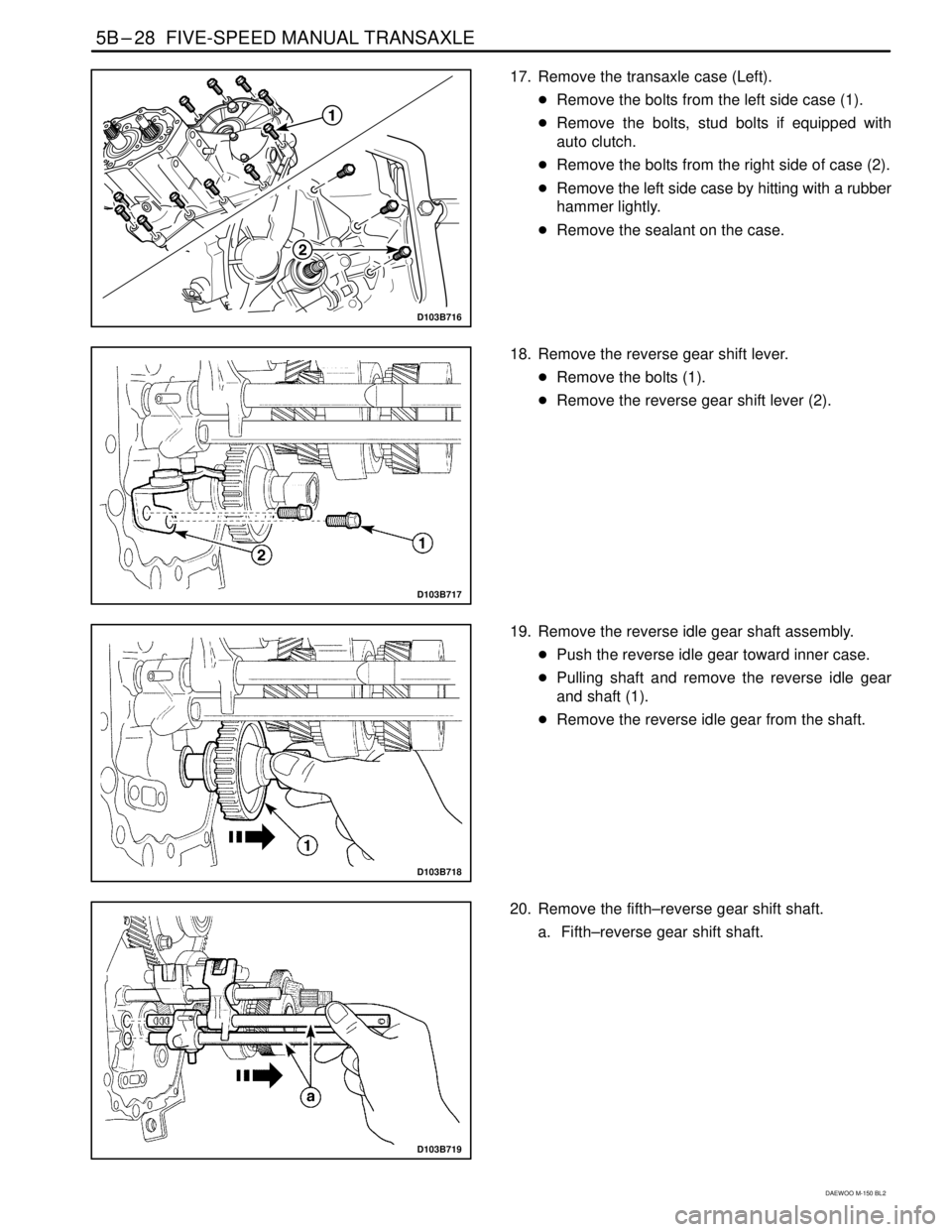
17. Remove the transaxle case (Left).
�Remove the bolts from the left side case (1).
�Remove the bolts, stud bolts if equipped with
auto clutch.
�Remove the bolts from the right side of case (2).
�Remove the left side case by hitting with a rubber
hammer lightly.
�Remove the sealant on the case.
D103B717
18. Remove the reverse gear shift lever.
�Remove the bolts (1).
�Remove the reverse gear shift lever (2).
D103B718
19. Remove the reverse idle gear shaft assembly.
�Push the reverse idle gear toward inner case.
�Pulling shaft and remove the reverse idle gear
and shaft (1).
�Remove the reverse idle gear from the shaft.
D103B719
20. Remove the fifth–reverse gear shift shaft.
a. Fifth–reverse gear shift shaft.
Page 661 of 1184
.
Tighten
Tighten the n")
5B–36 FIVE-SPEED MANUAL TRANSAXLE
DAEWOO M-150 BL2
D13B744A
24. Install the backup light switch and the speedometer
driven gear assembly.
�Install the backup light switch (1).
Tighten
Tighten the nut to 15–18 N�m (11–13 lb-ft) (a).
�Install the speedometer driven gear assembly
(2).
Tighten
Tighten the bolt to 4–7 N�m (35–62 lb-in) (b).
�Install the hydraulic pump assembly (If equipped
with auto clutch). Refer to Section 5D, Auto
Clutch.
D13B7452
25. Install the transaxle mount.
�Install the mount (1).
Tighten
�Tighten the bolts to 55–65 N�m (41–48 lb-ft) (a).
�Tighten the nut to 55–65 N�m (41–48 lb-ft) (b).
D13B701A
26. Install the related clutch parts. Refer to Section 5C,
Clutch.
27. Remove the transaxle assembly from transaxle
stand.
�Remove the transaxle assembly using the trans-
axle fixture DW220–010A.
28. Install the transaxle assembly. Refer to “Manual
Transaxle Assembly” in this section.
D103B746
INPUT SHAFT
Tools Required
DW09921–57810 Gear, Bearing Remover
DW09925–98221 Gear, Bearing Installer
DW09940–53111 Gear, Bearing Installer
Disassembly Procedure
1. Remove the gear unit. Refer to “Gear Unit” in this
section.
2. Remove the input shaft right side bearing.
�Position the bearing to the gear, bearing remover
DW09921–57810.
�Remove the bearing by pressing (1).
Page 678 of 1184

FIVE-SPEED MANUAL TRANSAXLE 5B–53
DAEWOO M-150 BL2
FASTENER TIGHTENING SPECIFICATIONS
ApplicationN�mLb-FtLb-In
5th/Reverse Gear Shift Shaft Bolt10 – 167 – 12–
Back Up Light Switch Nut15 – 1811 – 13–
Counter Shaft 5th Gear Nut60 – 8044 – 59–
Crankshaft Position Sensor Bolt5 – 8–44 – 70
Differential Ring Gear Bolt80 – 10059 – 74–
Engine Mounting Front Bracket Bolt
(Cylinder Block Side)35 – 4125 – 30–
Engine Mounting Front Damping Bush Bolt
(Crossmember Side)35 – 4125 – 30–
Engine Mounting Front Damping Bush Bolts
(Crossmember Side)45 – 5533 – 41–
Engine Mounting Front Damping Bush Bolt/Nut
(Bracket Side)68 – 8351 – 61–
Front Exhaust Pipe Nut
(Exhaust Manifold Side/Muffler Side)25 – 3518 – 25–
Gear Shift Control Case Bolt18 – 2813 – 21–
Gear Shift Lever Bolt4 – 7–35 – 62
High Speed Shift Shaft Bolt10 – 167 – 12–
Low Speed Shift Shaft Bolt10 – 167 – 12–
Oil Drain Plug25 – 3018 – 22–
Oil Level Plug36 – 5426 – 40–
Radiator Lower Hose Bracket Bolts8 – 15–70 – 132
Reverse Idle Gear Shaft Bolt18 – 2813 – 21–
Reverse Shift Lever Bolt18 – 2813 – 21–
Select Cable Nut(Shift Lever Side)8 – 12–71 – 106
Select Lever Bolt18 – 2813 – 21–
Side Cover Plate Screw6 – 7–53 – 62
Shift Guide Bolt18 – 2813 – 21–
Shift Interlock Bolt18 – 2813 – 21–
Side Cover Bolt8 – 12–71 – 106
Speedometer Driven Gear Bolt4 – 7–35 – 62
Starter Motor Bolt18 – 2813 – 21–
Transaxle Case Bolt15 – 2211 – 16–
Transaxle Case(left) Cap Bolt8 – 12–71 – 106
Transaxle Lower Bolt and Nut(Engine Side)55 – 6541 – 48–
Transaxle Mounting Bolt(Body Side)45 – 5533 – 41–
Transaxle Mounting Bolt and Nut(Transaxle Side)55 – 6541 – 48–
Transaxle Upper Bolt(Engine Side)55 – 6541 – 48–
Transaxle Under Cover Bolt35 – 5525 – 41–


4 Case Cap(Left)
5 Back Up Light Switch
6 Trans")