Page 57 of 96

Downloaded from www.Manualslib.com manuals search engine 57
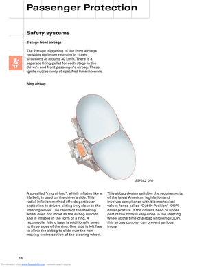
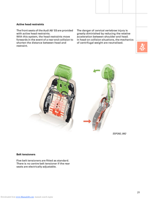
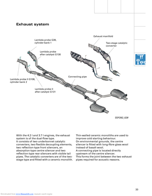
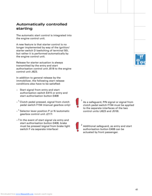
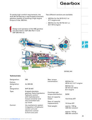
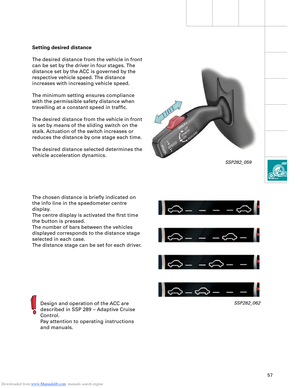
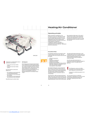
Setting desired distance
The desired distance from the vehicle in front
can be set by the driver in four stages. The
distance set by the ACC is governed by the
respective vehicle speed. The distance
increases with increasing vehicle speed.
The minimum setting ensures compliance
with the permissible safety distance when
travelling at a constant speed in traffic.
The desired distance from the vehicle in front
is set by means of the sliding switch on the
stalk. Actuation of the switch increases or
reduces the distance by one stage each time.
The desired distance selected determines the
vehicle acceleration dynamics.
The chosen distance is briefly indicated on
the info line in the speedometer centre
display.
The centre display is activated the first time
the button is pressed.
The number of bars between the vehicles
displayed corresponds to the distance stage
selected in each case.
The distance stage can be set for each driver.
Design and operation of the ACC are
described in SSP 289 – Adaptive Cruise
Control.
Pay attention to operating instructions
and manuals.SSP282_062
SSP282_059
Page 58 of 96

Downloaded from www.Manualslib.com manuals search engine 58
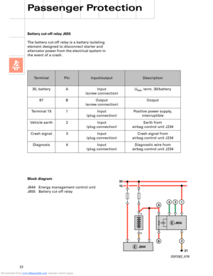
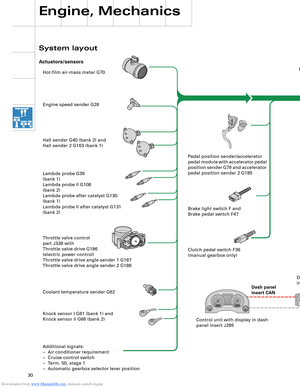
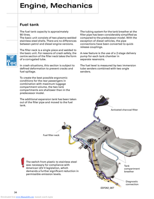
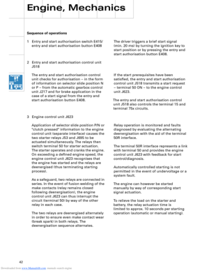
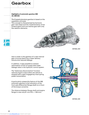
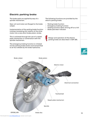
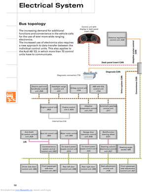
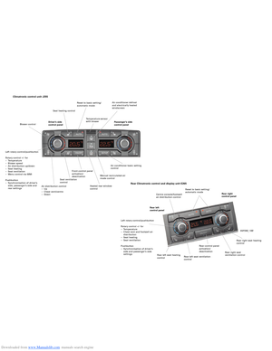
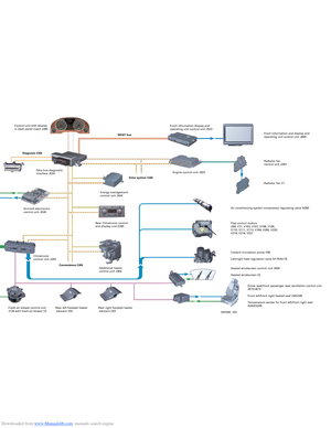
Bus topology
Electrical System
The increasing demand for additional
functions and convenience in the vehicle calls
for the use of ever more wide ranging
electronics.
The increased use of electronics also requires
a new approach to data transfer between the
individual control units. This also applies to
the Audi A8 ´03, in which more than 70 control
units have to communicate.
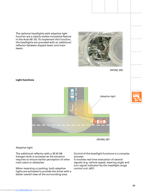
Distance regulation
control unit J428
Electric park and
handbrake control
unit J540Headlight range
control unit
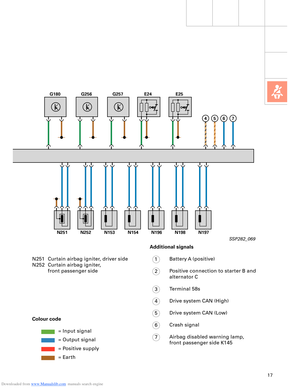
J431Airbag control unit
J234ABS with EDL
control unit
J104
Engine control unit
J623Adaptive
suspension control
unit J197 Engine control
unit 2 J624Automatic gearbox
control unit
J217
Anti-theft/
tilt system control
unit J529
Boot lid control unit
J605Wiper motor control
unit J400Garage door
operation control
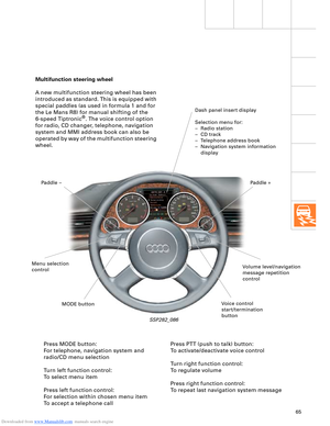
unit J530 Multifunction
steering wheel
E221
Convenenience
system central
control unit J393On-board power
supply control unit
J519
On-board power
supply control unit 2
J520Steering column
electronics control
unit J527Steering angle
sender G85
Driver side door
control unit J386Front passenger
side door
control unit J387Rear left door
control unit J388Rear right door
control unit J389Seat adjustment
control unit
J136Front passenger
seat adjustment
control unit J521 Control unit with
display in dash panel
insert J285
Diagnostic connection T16
Dash panel insert CAN
Drive system CAN
Diagnosis CAN
Convenience CAN
Internal bus link
LIN
Adaptive cruise control
CAN
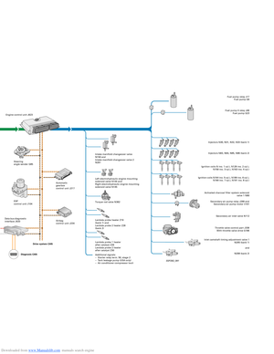
Page 59 of 96

Downloaded from www.Manualslib.com manuals search engine 59SSP282_063
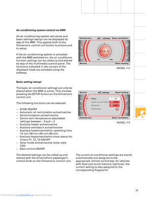
Telephone/
telematics control
unit J526
Front information
display and operating
unit control unit J523Rear DVD changer
R162Telephone
handset
R37
Control unit for rear
left
information display
and operating
unit J648
DSP control unit
J525
Navigation system
control unit
J401
TV tuner
R78
Digital radio
R147
Radio module R Chip card reader
control unit
J676 CD changer
R41 CD ROM drive
R92 Data bus diagnostic
interface J533
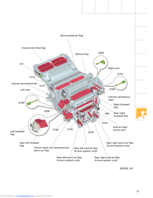
Fresh-air blower
control unit
J126Heated windscreen
control unit J505Rear left footwell
heater element Z42Rear right footwell
heater element Z43Driver seat
ventilation
control unit J672Front passenger
seat ventilation
control unit J673
Parking aid control
unit J446 Entry and start
authorisation
control unit J518 Energy
management
control unit J644 Rear seat
adjustment with
memory control
unit J522 Climatronic control
unit J255
Trailer detector
control unit J345
Rear Climatronic
control and
display unit E265Tyre pressure
monitor control unit
J502
Sun roof electronics
control unit J528
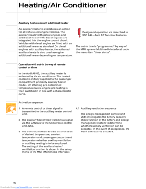
Additional heater
control unit J364Driver identification
control unit J589
Auxiliary heating
radio controlled
receiver R64 Sliding sun roof
motor V1 Front passenger
side rear seat
ventilation
control unit J675 Driver side rear seat
ventilation control
unit J674 Control unit for rear
right
information display
and operating
unit J649
MOST busBluetooth
TM
LIN
LIN
Page 60 of 96
 is
supplemented by the following bus systems:
– LIN bu")
Downloaded from www.Manualslib.com manuals search engine 60
LOCAL INTERCONNECT NETWORK
Electrical System
The familiar CAN bus (two-wire bus) is
supplemented by the following bus systems:
– LIN bus (single-wire data bus)
– MOST bus (optical data bus)
– Bluetooth
TM (wireless data bus)
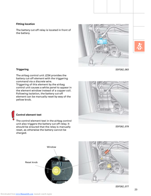
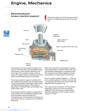
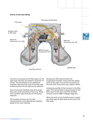
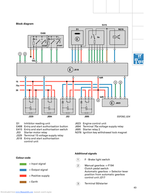
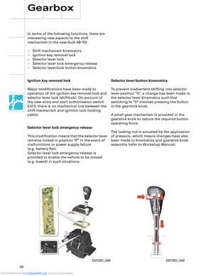
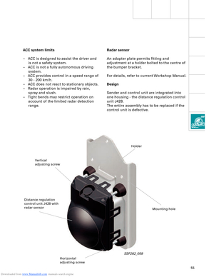
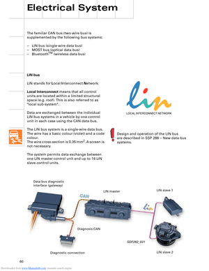
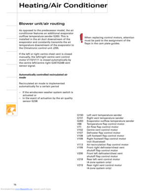
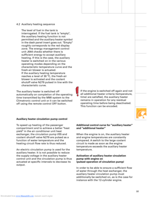
LIN bus
LIN stands for Local Interconnect Network.
Local Interconnect means that all control
units are located within a limited structural
space (e.g. roof). This is also referred to as
"local sub-system".
Data are exchanged between the individual
LIN bus systems in a vehicle by one control
unit in each case using the CAN data bus.
The LIN bus system is a single-wire data bus.
The wire has a basic colour (violet) and a code
colour.
The wire cross-section is 0.35 mm
2. A screen is
not necessary.
The system permits data exchange between
one LIN master control unit and up to 16 LIN
slave control units.
SSP282_031
Design and operation of the LIN bus
are described in SSP 286 – New data bus
systems.
Diagnostic connection Data bus diagnostic
interface (gateway)
LIN master
LIN slave 2 LIN slave 1
Diagnosis CAN
Page 61 of 96
 Cooperation\".")
Downloaded from www.Manualslib.com manuals search engine 61
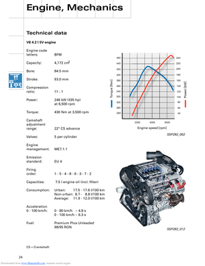
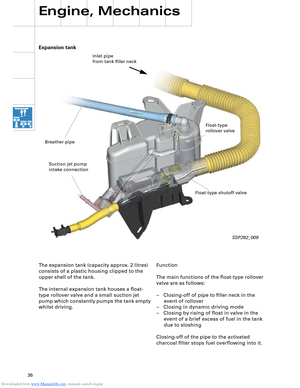
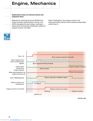
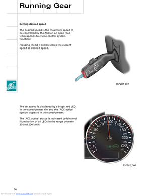
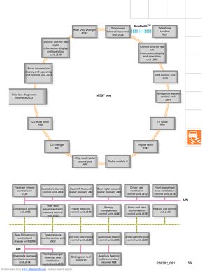
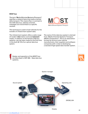
Media Oriented Systems Transport
R
The name of this data bus system is derived
from "Media Oriented Systems Transport
(MOST) Cooperation". This is an association
formed by various motor vehicle
manufacturers, their suppliers and software
companies with a view to developing
a standard high-speed data transfer system. MOST bus
The term "Media Oriented Systems Transport"
signifies a network featuring media-oriented
data transport. This means that, in contrast to
the CAN data bus, address-oriented
messages are transmitted to a specific
receiver.
This technique is used in Audi vehicles for the
transfer of infotainment system data.
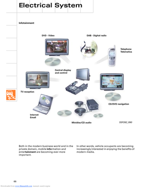
The infotainment system offers a wide range
of modern information and entertainment
media. In addition to the familiar CAN bus
systems, use has been made for the first time
in the Audi A8 ´03 of an optical data bus
system.
SSP282_034
Design and operation of the MOST bus
are described in SSP 286 – New data bus
systems.
System manager
Sound system
DisplayOperating unit
Page 62 of 96

Downloaded from www.Manualslib.com manuals search engine 62
Electrical System
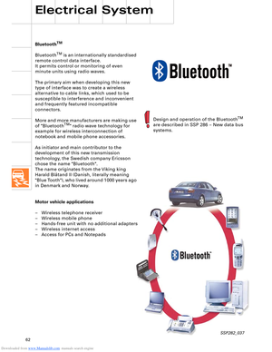
BluetoothTM
BluetoothTM is an internationally standardised
remote control data interface.
It permits control or monitoring of even
minute units using radio waves.
The primary aim when developing this new
type of interface was to create a wireless
alternative to cable links, which used to be
susceptible to interference and inconvenient
and frequently featured incompatible
connectors.
More and more manufacturers are making use
of "Bluetooth
TM" radio wave technology for
example for wireless interconnection of
notebook and mobile phone accessories.
As initiator and main contributor to the
development of this new transmission
technology, the Swedish company Ericsson
chose the name "Bluetooth".
The name originates from the Viking king
Harald Blåtand II (Danish, literally meaning
"Blue Tooth"), who lived around 1000 years ago
in Denmark and Norway.
Motor vehicle applications
– Wireless telephone receiver
– Wireless mobile phone
– Hands-free unit with no additional adapters
– Wireless internet access
– Access for PCs and Notepads
SSP282_037
Design and operation of the BluetoothTM
are described in SSP 286 – New data bus
systems.
Page 63 of 96

Downloaded from www.Manualslib.com manuals search engine 63
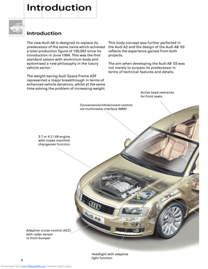
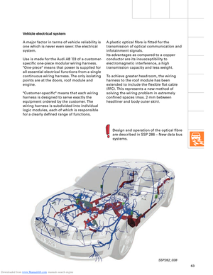
Vehicle electrical system
A major factor in terms of vehicle reliability is
one which is never even seen: the electrical
system.
Use is made for the Audi A8 ´03 of a customer-
specific one-piece modular wiring harness.
"One-piece" means that power is supplied for
all essential electrical functions from a single
continuous wiring harness. The only isolating
points are at the doors, roof module and
engine.
"Customer-specific" means that each wiring
harness is designed to serve exactly the
equipment ordered by the customer. The
wiring harness is subdivided into individual
logic modules, each of which is responsible
for a clearly defined range of functions.
SSP282_038
Design and operation of the optical fibre
are described in SSP 286 – New data bus
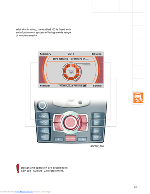
systems. A plastic optical fibre is fitted for the
transmission of optical communication and
infotainment signals.
Its advantages as compared to a copper
conductor are its insusceptibility to
electromagnetic interference, a high
transmission capacity and less weight.
To achieve greater headroom, the wiring
harness to the roof module has been
extended to include the flexible flat cable
(FFC). This represents a new method of
solving the wiring problem in extremely
confined spaces (max. 2 mm between
headliner and body outer skin).
Page 64 of 96

Downloaded from www.Manualslib.com manuals search engine 64
Electrical System
Convenience and security
electronics
"Advanced Key" entry and start
authorisation system
"Advanced Key" can be taken to mean an
"advanced locking and security system".
It takes the form of a non-contacting key
recognition system. With the "Advanced Key"
package, the "Vehicle unlocking" and "Vehicle
locking" functions by way of a mechanical or
remote control key are supplemented by the non-
contacting functions "Vehicle unlocking" and
"Vehicle locking".
Functions
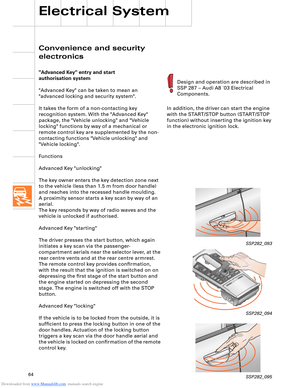
Advanced Key "unlocking"
The key owner enters the key detection zone next
to the vehicle (less than 1.5 m from door handle)
and reaches into the recessed handle moulding.
aerial.
The key responds by way of radio waves and the
vehicle is unlocked if authorised.
Advanced Key "starting"
The driver presses the start button, which again
initiates a key scan via the passenger-
compartment aerials near the selector lever, at the
rear centre vents and at the rear centre armrest.
The remote control key provides confirmation,
with the result that the ignition is switched on on
depressing the first stage of the start button and
the engine started on depressing the second
stage. The engine is switched off with the STOP
button.
Advanced Key "locking"
If the vehicle is to be locked from the outside, it is
sufficient to press the locking button in one of the
door handles. Actuation of the locking button
triggers a key scan via the door handle aerial and
the vehicle is locked on confirmation of the remote
control key.In addition, the driver can start the engine
with the START/STOP button (START/STOP
function) without inserting the ignition key
in the electronic ignition lock.
SSP282_093
SSP282_094
SSP282_095
Design and operation are described in
SSP 287 – Audi A8 ´03 Electrical
Components.
A proximity sensor starts a key scan by way of an