Page 25 of 96
Downloaded from www.Manualslib.com manuals search engine 25
200040006000
260
280 300
320
340 360380 400
420 440
46040
60
80
100
120
140
160
180
200
220
240
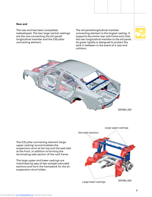
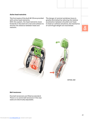
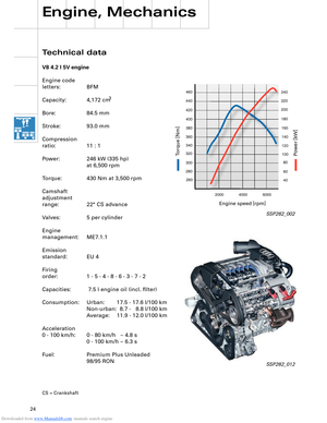
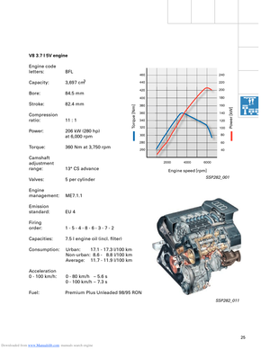
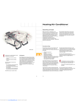
V8 3.7 l 5V engine
Engine code
letters: BFL
Capacity:
3
Bore: 84.5 mm
Stroke: 82.4 mm
Compression
ratio: 11 : 1
Power: 206 kW (280 hp)
at 6,000 rpm
Torque: 360 Nm at 3,750 rpm
Camshaft
adjustment
range: 13° CS advance
Valves: 5 per cylinder
Engine
management: ME7.1.1
Emission
standard: EU 4
Firing
order: 1 - 5 - 4 - 8 - 6 - 3 - 7 - 2
Capacities: 7.5 l engine oil (incl. filter)
Consumption: Urban: 17.1 - 17.3 l/100 km Non-urban: 8.6 - 8.8 l/100 km
Average: 11.7 - 11.9 l/100 km
Acceleration
0 - 100 km/h: 0 - 80 km/h – 5.6 s 0 - 100 km/h – 7.3 s
Fuel: Premium Plus Unleaded 98/95 RON
SSP282_001
SSP282_011
Engine speed [rpm]
P
ower [kW]
T
orq ue [Nm]
3,697 cm
Page 26 of 96
Downloaded from www.Manualslib.com manuals search engine 26
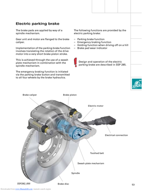
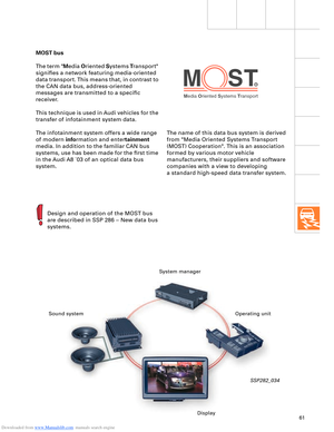
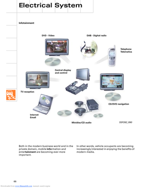
Engine, Mechanics
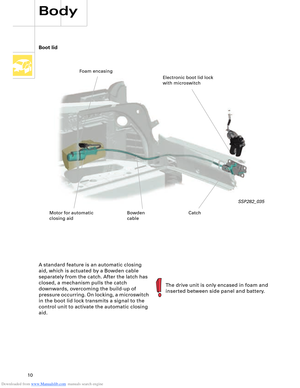
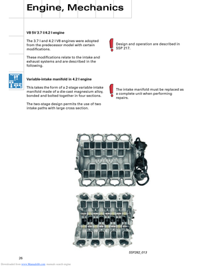
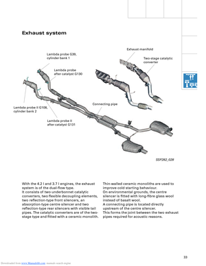
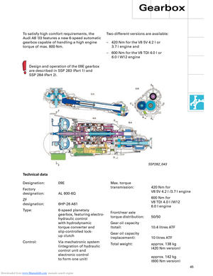
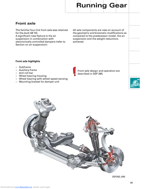
V8 5V 3.7 l/4.2 l engine
The 3.7 l and 4.2 l V8 engines were adopted
from the predecessor model with certain
modifications.
These modifications relate to the intake and
exhaust systems and are described in the
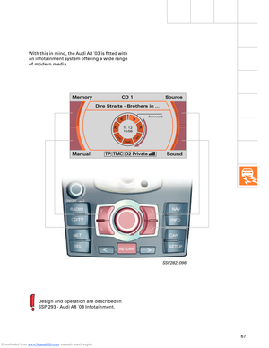
following.Design and operation are described in
SSP 217.
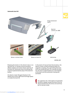
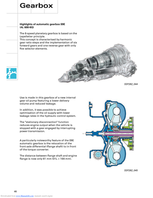
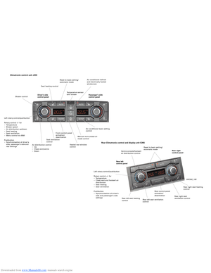
Variable-intake manifold in 4.2 l engine
This takes the form of a 2-stage variable-intake
manifold made of a die-cast magnesium alloy,
bonded and bolted together in four sections.
The two-stage design permits the use of two
intake paths with large cross section.The intake manifold must be replaced as
a complete unit when performing
repairs.
SSP282_013
Page 27 of 96
Downloaded from www.Manualslib.com manuals search engine 27
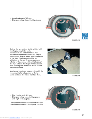
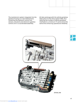
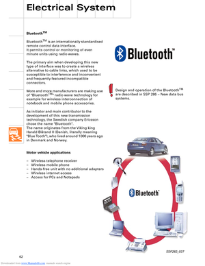
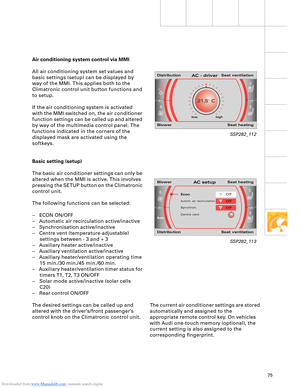
– Long intake path, 705 mm
– Changeover flap closed for high torque
Each of the two splined shafts is fitted with
four flaps per cylinder bank.
The shape of the rubber-encased flaps
ensures unimpeded air flow in the torque
position and reliable power position sealing
of the duct. This is a prerequisite for
utilisation of the gas-dynamic resonance
effects. In the power position, the backs of
the flaps take on the shape of the duct wall,
thus allowing low-resistance intake air flow
into the cylinders.
Mechanical couplings provide a link with the
vacuum units for adjustment of the two
shafts and thus the intake manifold flaps.
– Short intake path, 322 mm
– Changeover flap open for high power
with high air throughput
Changeover from long to short at 4,480 rpm
Changeover from short to long at 4,320 rpm
SSP282_014
SSP282_016
SSP282_015
Page 28 of 96
Downloaded from www.Manualslib.com manuals search engine 28
Engine, Mechanics
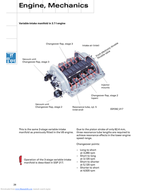
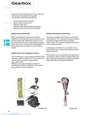
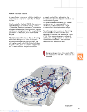
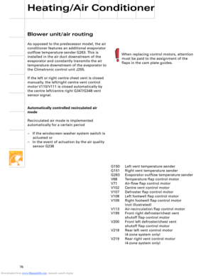
Variable-intake manifold in 3.7 l engine
Operation of the 3-stage variable-intake
manifold is described in SSP 217.
SSP282_017
This is the same 3-stage variable-intake
manifold as previously fitted in the V8 engine.Due to the piston stroke of only 82.4 mm,
three resonance tube lengths are required to
achieve resonance effects in the lower engine
speed range.
Changeover points:
– Long to short
at 3,280 rpm
– Short to long
at 3,120 rpm
– Short to shorter
at 5,120 rpm
– Shorter to short
at 4,920 rpm
Changeover flap, stage 3
From electronic throttle
Throttle valve
Intake air (inlet)
Changeover flap, stage 2
(open)
Resonance tube, cyl. 5
(inlet end) Vacuum unit
Changeover flap, stage 2 Vacuum unit
Changeover flap, stage 3
Injector
mounts
Page 29 of 96
Downloaded from www.Manualslib.com manuals search engine 29
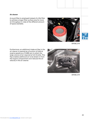
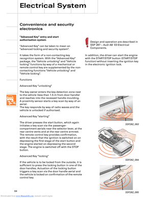
Air cleaner
A round filter is employed instead of a flat filter
to achieve a larger filter surface area for more
air throughput in view of the different amount
of space available.
Furthermore, an additional intake air flap in the
air cleaner is opened as a function of load at
engine speeds as of 3,000 rpm to attain the
large volume of air required at full throttle. This
flap enables additional air to be drawn in from
the engine compartment and reduces the air
velocity in the air cleaner.
SSP282_018
SSP282_019
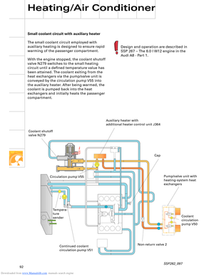
Page 30 of 96
 and
Hall sender 2 G163 (bank 1)
Lambda probe G39
(bank 1)
Lamb")
Downloaded from www.Manualslib.com manuals search engine 30
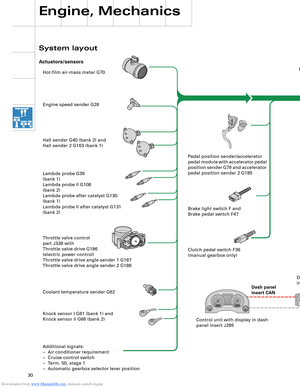
Hot-film air-mass meter G70
Engine speed sender G28
Hall sender G40 (bank 2) and
Hall sender 2 G163 (bank 1)
Lambda probe G39
(bank 1)
Lambda probe II G108
(bank 2)
Lambda probe after catalyst G130
(bank 1)
Lambda probe II after catalyst G131
(bank 2)
Throttle valve control
part J338 with
Throttle valve drive G186
(electric power control)
Throttle valve drive angle sender 1 G187
Throttle valve drive angle sender 2 G188
Coolant temperature sender G62
Knock sensor I G61 (bank 1) and
Knock sensor II G66 (bank 2)
Additional signals:
– Air conditioner requirement
– Cruise control switch
– Term. 50, stage 1
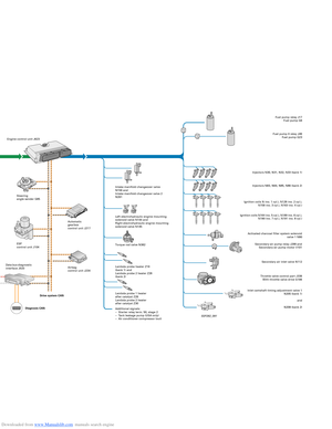
– Automatic gearbox selector lever positionEngine control unit J623
Steering
angle sender G85
ESP
control unit J104
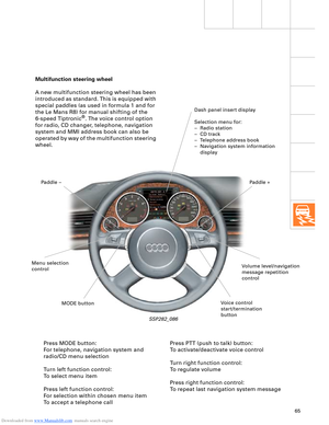
Dash panel
insert CANAutomatic
gearbox
control unit J217
Airbag
control unit J234Intake manifold changeover valve
N156 and
Intake manifold changeover valve 2
N261
Left electrohydraulic engine mounting
solenoid valve N144 and
Right electrohydraulic engine mounting
solenoid valve N145
Torque rod valve N382
Lambda probe heater Z19
(bank 1) and
Lambda probe 2 heater Z28
(bank 2)
Lambda probe 1 heater
after catalyst Z29
Lambda probe 2 heater
after catalyst Z30
Additional signals:
– Starter relay term. 50, stage 2
– Tank leakage pump (USA only)
– Air conditioner compressor (out)Fuel pump relay J17
Fuel pump G6
Fuel pump II relay J49
Fuel pump G23
Injectors N30, N31, N32, N33 (bank 1)
Injectors N83, N84, N85, N86 (bank 2)
Ignition coils N (no. 1 cyl.), N128 (no. 2 cyl.),
N158 (no. 3 cyl.), N163 (no. 4 cyl.)
Ignition coils N164 (no. 5 cyl.), N189 (no. 6 cyl.),
N190 (no. 7 cyl.), N191 (no. 8 cyl.)
Activated charcoal filter system solenoid
valve 1 N80
Secondary-air pump relay J299 and
Secondary-air pump motor V101
Secondary air inlet valve N112
Throttle valve control part J338
With throttle valve drive G186
Inlet camshaft timing adjustment valve 1
N205 (bank 1)
and
N208 (bank 2) Pedal position sender/accelerator
pedal module with accelerator pedal
position sender G79 and accelerator
pedal position sender 2 G185
Brake light switch F and
Brake pedal switch F47
Clutch pedal switch F36
(manual gearbox only)
Control unit with display in dash
panel insert J285Data bus diagnostic
interface J533
Engine, Mechanics
System layout
Actuators/sensors
SSP282_091 Drive system CAN
Diagnosis CAN
Page 31 of 96
 and
Hall sender 2 G163 (bank 1)
Lambda probe G39
(bank 1)
Lamb")
Downloaded from www.Manualslib.com manuals search engine 30
Hot-film air-mass meter G70
Engine speed sender G28
Hall sender G40 (bank 2) and
Hall sender 2 G163 (bank 1)
Lambda probe G39
(bank 1)
Lambda probe II G108
(bank 2)
Lambda probe after catalyst G130
(bank 1)
Lambda probe II after catalyst G131
(bank 2)
Throttle valve control
part J338 with
Throttle valve drive G186
(electric power control)
Throttle valve drive angle sender 1 G187
Throttle valve drive angle sender 2 G188
Coolant temperature sender G62
Knock sensor I G61 (bank 1) and
Knock sensor II G66 (bank 2)
Additional signals:
– Air conditioner requirement
– Cruise control switch
– Term. 50, stage 1
– Automatic gearbox selector lever positionEngine control unit J623
Steering
angle sender G85
ESP
control unit J104
Dash panel
insert CANAutomatic
gearbox
control unit J217
Airbag
control unit J234Intake manifold changeover valve
N156 and
Intake manifold changeover valve 2
N261
Left electrohydraulic engine mounting
solenoid valve N144 and
Right electrohydraulic engine mounting
solenoid valve N145
Torque rod valve N382
Lambda probe heater Z19
(bank 1) and
Lambda probe 2 heater Z28
(bank 2)
Lambda probe 1 heater
after catalyst Z29
Lambda probe 2 heater
after catalyst Z30
Additional signals:
– Starter relay term. 50, stage 2
– Tank leakage pump (USA only)
– Air conditioner compressor (out)Fuel pump relay J17
Fuel pump G6
Fuel pump II relay J49
Fuel pump G23
Injectors N30, N31, N32, N33 (bank 1)
Injectors N83, N84, N85, N86 (bank 2)
Ignition coils N (no. 1 cyl.), N128 (no. 2 cyl.),
N158 (no. 3 cyl.), N163 (no. 4 cyl.)
Ignition coils N164 (no. 5 cyl.), N189 (no. 6 cyl.),
N190 (no. 7 cyl.), N191 (no. 8 cyl.)
Activated charcoal filter system solenoid
valve 1 N80
Secondary-air pump relay J299 and
Secondary-air pump motor V101
Secondary air inlet valve N112
Throttle valve control part J338
With throttle valve drive G186
Inlet camshaft timing adjustment valve 1
N205 (bank 1)
and
N208 (bank 2) Pedal position sender/accelerator
pedal module with accelerator pedal
position sender G79 and accelerator
pedal position sender 2 G185
Brake light switch F and
Brake pedal switch F47
Clutch pedal switch F36
(manual gearbox only)
Control unit with display in dash
panel insert J285Data bus diagnostic
interface J533
Engine, Mechanics
System layout
Actuators/sensors
SSP282_091 Drive system CAN
Diagnosis CAN
Page 32 of 96

Downloaded from www.Manualslib.com manuals search engine 32
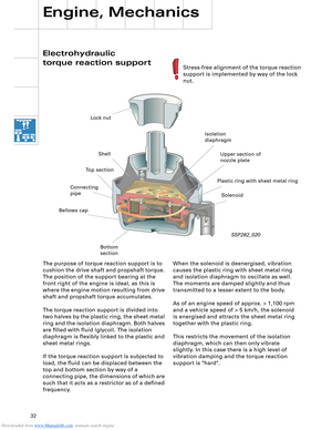
Electrohydraulic
torque reaction support
Engine, Mechanics
When the solenoid is deenergised, vibration
causes the plastic ring with sheet metal ring
and isolation diaphragm to oscillate as well.
The moments are damped slightly and thus
transmitted to a lesser extent to the body.
As of an engine speed of approx. > 1,100 rpm
and a vehicle speed of > 5 km/h, the solenoid
is energised and attracts the sheet metal ring
together with the plastic ring.
This restricts the movement of the isolation
diaphragm, which can then only vibrate
slightly. In this case there is a high level of
vibration damping and the torque reaction
support is "hard". The purpose of torque reaction support is to
cushion the drive shaft and propshaft torque.
The position of the support bearing at the
front right of the engine is ideal, as this is
where the engine motion resulting from drive
shaft and propshaft torque accumulates.
The torque reaction support is divided into
two halves by the plastic ring, the sheet metal
ring and the isolation diaphragm. Both halves
are filled with fluid (glycol). The isolation
diaphragm is flexibly linked to the plastic and
sheet metal rings.
If the torque reaction support is subjected to
load, the fluid can be displaced between the
top and bottom section by way of a
connecting pipe, the dimensions of which are
such that it acts as a restrictor as of a defined
frequency.
SSP282_020
Stress-free alignment of the torque reaction
support is implemented by way of the lock
nut.
Lock nut
Shell
Bellows cap
Bottom
sectionIsolation
diaphragm
Plastic ring with sheet metal ringUpper section of
nozzle plate
Solenoid Connecting
pipeTop section