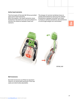
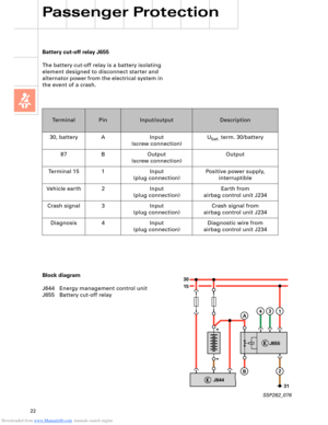
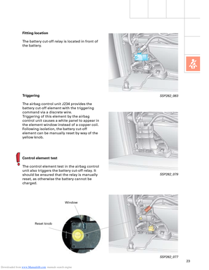
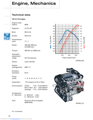
Page 49 of 96
Downloaded from www.Manualslib.com manuals search engine 49
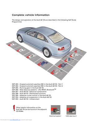
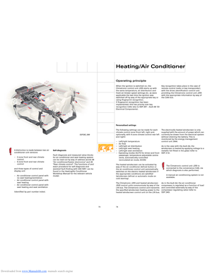
All axle components are new on account of
the geometric and kinematic modifications as
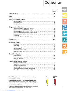
compared to the predecessor model, the air
suspension and the weight reductions
achieved.
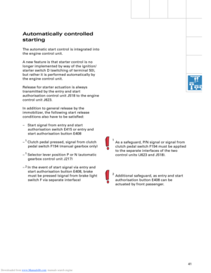
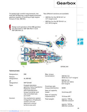
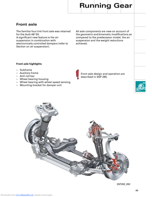
Front axle
The familiar four-link front axle was retained
for the Audi A8 '03.
A significant new feature is the air
suspension in combination with
electronically controlled dampers (refer to
Section on air suspension).
Front axle highlights
– Subframe
– Auxiliary frame
– Anti-roll bar
– Wheel bearing housing
– Wheel bearing with wheel speed sensing
– Mounting bracket for damper unit
Front axle design and operation are
described in SSP 285.
SSP282_050
Running Gear
Page 50 of 96
Downloaded from www.Manualslib.com manuals search engine 50
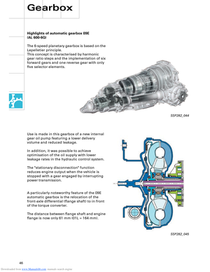
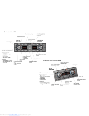
All axle components are new on account of
the geometric and kinematic modifications as
compared to the predecessor model, the air
suspension and the weight reductions
achieved.
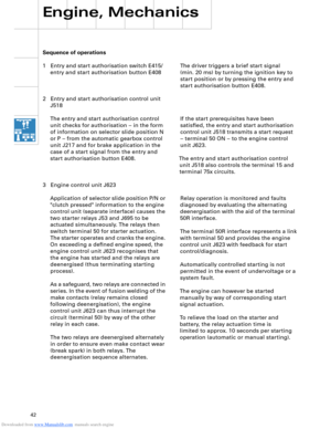
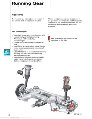
Rear axle highlights
– Use of air suspension in conjunction with
electronically controlled damping
– Aluminium subframe to help
reduce weight
– Connection of anti-roll bar to trapezium
link
– Use of shorter track rod to reduce change
in toe on compression and extension of
suspension
– Use of ball studs to connect wheel bearing
housing and track rod, thus reducing
secondary spring rate
– Use of slotted bonded rubber bushes in
upper transverse link and connection
between trapezium link and subframe
Rear axle design and operation are
described in SSP 285.
Rear axle
The rear axle is a more advanced version of
the familiar Audi A8 trapezium-link axle.
Running Gear
SSP282_051
Page 51 of 96

Downloaded from www.Manualslib.com manuals search engine 51
4-level air suspension
The introduction of the Audi A8 ´03 is
accompanied by a system featuring new
technical details and functions. The major
differences with respect to the familiar Audi
allroad quattro
® system are as follows:
EDC instead of PDC damping
The control system makes allowance for the
currently applicable driving status. Wheel
movement (unsprung masses) and body
movement (sprung masses) are detected.
Various damping characteristic curves are
implemented within the scope of three
selectable programs (modes) and each
damper can be controlled individually.
Control concept
Integration into the MMI makes for
convenient, logical and easy to remember
control action.
Extended range of sensors
Use is made of three acceleration sensors to
detect body movement.
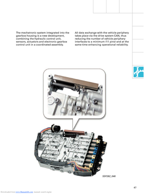
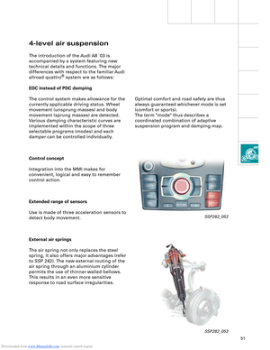
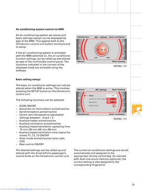
External air springs
The air spring not only replaces the steel
spring, it also offers major advantages (refer
to SSP 242). The new external routing of the
air spring through an aluminium cylinder
permits the use of thinner-walled bellows.
This results in an even more sensitive
response to road surface irregularities.
SSP282_052
SSP282_053
Optimal comfort and road safety are thus
always guaranteed whichever mode is set
(comfort or sports).
The term "mode" thus describes a
coordinated combination of adaptive
suspension program and damping map.
Page 52 of 96
Downloaded from www.Manualslib.com manuals search engine 52
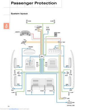
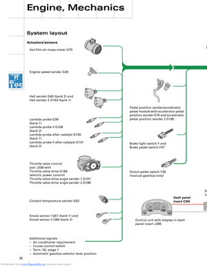
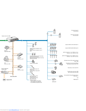
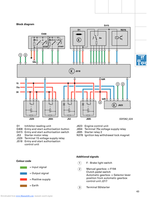
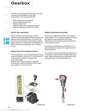
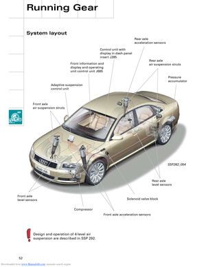
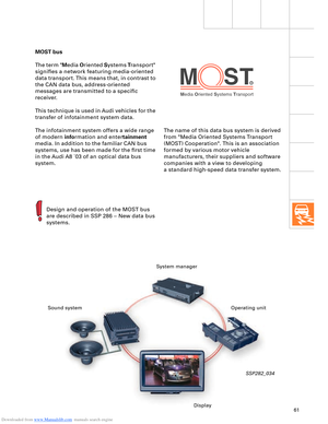
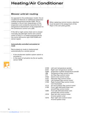
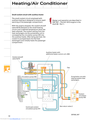
System layout
Running Gear
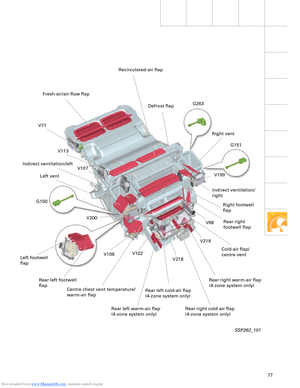
SSP282_054
Design and operation of 4-level air
suspension are described in SSP 292.
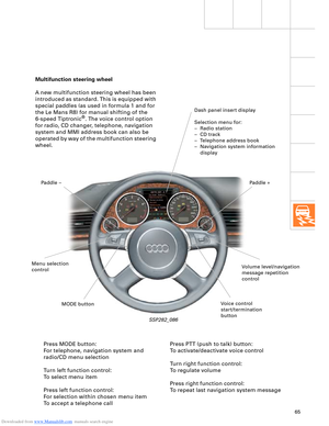
Front information and
display and operating
unit control unit J685
Front axle
level sensorsSolenoid valve blockRear axle
level sensorsPressure
accumulator
Adaptive suspension
control unitRear axle
air suspension struts Rear axle
acceleration sensors
CompressorControl unit with
display in dash panel
insert J285
Front axle
air suspension struts
Front axle acceleration sensors
Page 53 of 96
Downloaded from www.Manualslib.com manuals search engine 53
The following functions are provided by the
electric parking brake:
– Parking brake function
– Emergency braking function
– Holding function when driving off on a hill
– Brake pad wear indicator
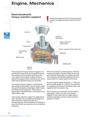
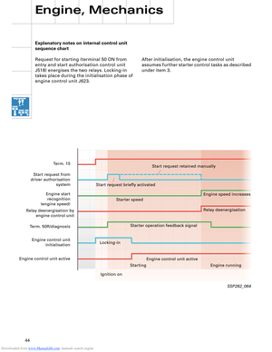
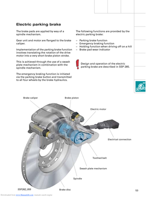
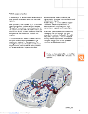
Electric parking brake
The brake pads are applied by way of a
spindle mechanism.
Gear unit and motor are flanged to the brake
caliper.
Implementation of the parking brake function
involves translating the rotation of the drive
motor into a very short brake piston stroke.
This is achieved through the use of a swash
plate mechanism in combination with the
spindle mechanism.
The emergency braking function is initiated
via the parking brake button and transmitted
to all four wheels by the brake hydraulics.
Design and operation of the electric
parking brake are described in SSP 285.
SSP282_055
Toothed belt
Swash plate mechanismElectric motor Brake piston
SpindleElectrical connection
Brake disc Brake caliper
Page 54 of 96

Downloaded from www.Manualslib.com manuals search engine 54
Driver convenience is further enhanced, as
fewer accelerator and brake pedal operations
are required. Speed restrictions and safety
factors are reliably observed and the flow of
traffic thus better regulated.
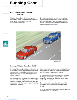
ACC (Adaptive Cruise
Control)
Adaptive Cruise Control is a new system
designed to assist drivers and offers a much
wider range of functions than the
conventional Tempomat.
Running Gear
If the distance is less than desired, the vehicle is
decelerated by reducing power, changing gear
and if necessary applying the brakes.
In the interests of comfort, maximum possible
braking is restricted to approx. 25 % of the
maximum deceleration potential of the brake
system (full braking).
The control action is designed to assist the
driver and thus contributes to greater road
safety.
In certain traffic situations, active braking by the
driver may still be necessary. Summary of Adaptive Cruise Control (ACC)
The basic Adaptive Cruise Control function is
to maintain a driver-selectable distance from
the vehicle in front. ACC thus represents the
logical next step on from the original cruise
control system.
The distance from and speed of the vehicle in
front are determined by a radar sensor. If the
distance is greater than desired, the vehicle is
accelerated until the required speed input by
the driver is achieved.
SSP282_057
Page 55 of 96
Downloaded from www.Manualslib.com manuals search engine 55
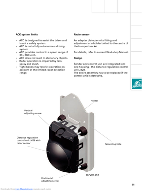
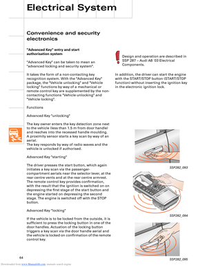
Radar sensor
An adapter plate permits fitting and
adjustment at a holder bolted to the centre of
the bumper bracket.
For details, refer to current Workshop Manual.
Design
Sender and control unit are integrated into
one housing - the distance regulation control
unit J428.
The entire assembly has to be replaced if the
control unit is defective. ACC system limits
– ACC is designed to assist the driver and
is not a safety system.
– ACC is not a fully autonomous driving
system.
– ACC provides control in a speed range of
30 - 200 km/h.
– ACC does not react to stationary objects.
– Radar operation is impaired by rain,
spray and slush.
– Tight bends may restrict operation on
account of the limited radar detection
range.
SSP282_058
Vertical
adjusting screwHolder
Distance regulation
control unit J428 with
radar sensor
Horizontal
adjusting screwMounting hole
Page 56 of 96
Downloaded from www.Manualslib.com manuals search engine 56
SSP282_061
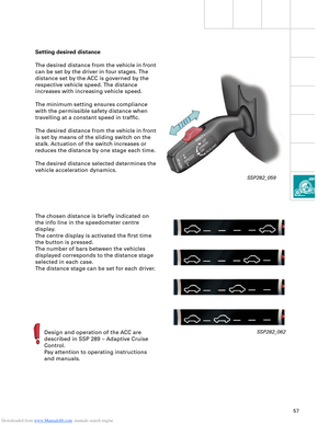
Setting desired speed
The desired speed is the maximum speed to
be controlled by the ACC on an open road
(corresponds to cruise control system
function).
Pressing the SET button stores the current
speed as desired speed.
Running Gear
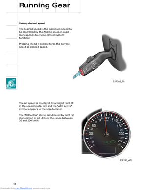
The set speed is displayed by a bright red LED
in the speedometer rim and the "ACC active"
symbol appears in the speedometer.
The "ACC active" status is indicated by faint red
illumination of all LEDs in the range between
30 and 200 km/h.
SSP282_060