Page 6 of 96
Downloaded from www.Manualslib.com manuals search engine 6
9712944
5051
1136
714 125
Brief outline
Body
SSP282_026
Kerb weight 1,780 kgGross weight 2,380 kg
Turning circle 12 mLuggage compartment volume approx. 500 l
Tank capacity approx. 90 litresDrag coefficient 0.27 Cd
1629
1894
1444
2028
1615
976
Page 24 of 96
Downloaded from www.Manualslib.com manuals search engine 24
Engine, Mechanics
200040006000
40
60
80
100
120
140
160
180
200
220
240
260
280 300
320
340 360380 400
420 440
460
Technical data
V8 4.2 l 5V engine
Engine code
letters: BFM
Capacity:
3
Bore: 84.5 mm
Stroke: 93.0 mm
Compression
ratio: 11 : 1
Power: 246 kW (335 hp)
at 6,500 rpm
Torque: 430 Nm at 3,500 rpm
Camshaft
adjustment
range: 22° CS advance
Valves: 5 per cylinder
Engine
management: ME7.1.1
Emission
standard: EU 4
Firing
order: 1 - 5 - 4 - 8 - 6 - 3 - 7 - 2
Capacities: 7.5 l engine oil (incl. filter)
Consumption: Urban: 17.5 - 17.6 l/100 km Non-urban: 8.7 - 8.8 l/100 km
Average: 11.9 - 12.0 l/100 km
Acceleration
0 - 100 km/h: 0 - 80 km/h – 4.8 s 0 - 100 km/h – 6.3 s
Fuel: Premium Plus Unleaded 98/95 RON
CS = Crankshaft
SSP282_002
SSP282_012
Engine speed [rpm]
P
ower [kW]
T
orq ue [Nm]
4,172 cm
Page 25 of 96
Downloaded from www.Manualslib.com manuals search engine 25
200040006000
260
280 300
320
340 360380 400
420 440
46040
60
80
100
120
140
160
180
200
220
240
V8 3.7 l 5V engine
Engine code
letters: BFL
Capacity:
3
Bore: 84.5 mm
Stroke: 82.4 mm
Compression
ratio: 11 : 1
Power: 206 kW (280 hp)
at 6,000 rpm
Torque: 360 Nm at 3,750 rpm
Camshaft
adjustment
range: 13° CS advance
Valves: 5 per cylinder
Engine
management: ME7.1.1
Emission
standard: EU 4
Firing
order: 1 - 5 - 4 - 8 - 6 - 3 - 7 - 2
Capacities: 7.5 l engine oil (incl. filter)
Consumption: Urban: 17.1 - 17.3 l/100 km Non-urban: 8.6 - 8.8 l/100 km
Average: 11.7 - 11.9 l/100 km
Acceleration
0 - 100 km/h: 0 - 80 km/h – 5.6 s 0 - 100 km/h – 7.3 s
Fuel: Premium Plus Unleaded 98/95 RON
SSP282_001
SSP282_011
Engine speed [rpm]
P
ower [kW]
T
orq ue [Nm]
3,697 cm
Page 34 of 96

Downloaded from www.Manualslib.com manuals search engine 34
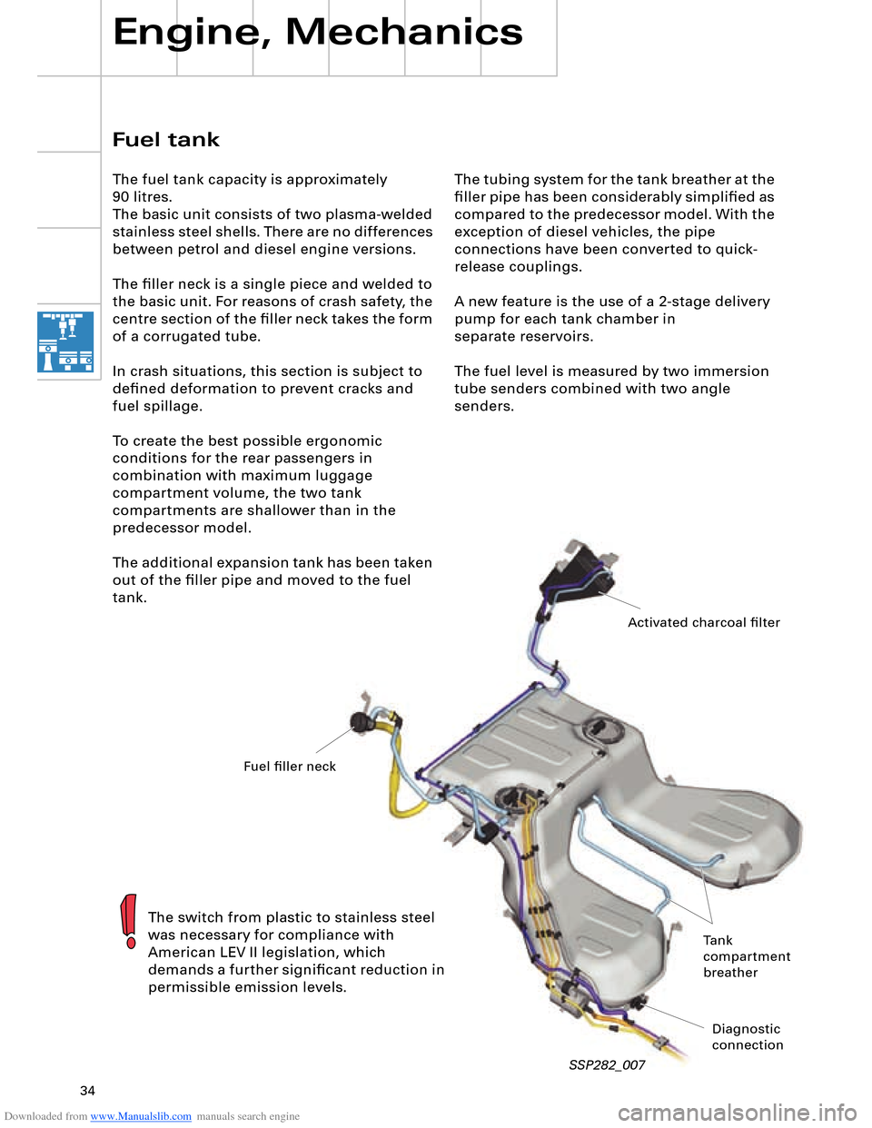
The tubing system for the tank breather at the
filler pipe has been considerably simplified as
compared to the predecessor model. With the
exception of diesel vehicles, the pipe
connections have been converted to quick-
release couplings.
A new feature is the use of a 2-stage delivery
pump for each tank chamber in
separate reservoirs.
The fuel level is measured by two immersion
tube senders combined with two angle
senders.
Engine, Mechanics
SSP282_007
Fuel tank
The fuel tank capacity is approximately
90 litres.
The basic unit consists of two plasma-welded
stainless steel shells. There are no differences
between petrol and diesel engine versions.
The filler neck is a single piece and welded to
the basic unit. For reasons of crash safety, the
centre section of the filler neck takes the form
of a corrugated tube.
In crash situations, this section is subject to
defined deformation to prevent cracks and
fuel spillage.
To create the best possible ergonomic
conditions for the rear passengers in
combination with maximum luggage
compartment volume, the two tank
compartments are shallower than in the
predecessor model.
The additional expansion tank has been taken
out of the filler pipe and moved to the fuel
tank.
The switch from plastic to stainless steel
was necessary for compliance with
American LEV II legislation, which
demands a further significant reduction in
permissible emission levels.
Activated charcoal filter
Fuel filler neck
Tank
compartment
breather
Diagnostic
connection
Page 36 of 96
Downloaded from www.Manualslib.com manuals search engine 36
Engine, Mechanics
Function
The main functions of the float-type rollover
valve are as follows:
– Closing-off of pipe to filler neck in the
event of rollover
– Closing in dynamic driving mode
– Closing by rising of float in valve in the
event of a brief excess of fuel in the tank
due to sloshing
Closing-off of the pipe to the activated
charcoal filter stops fuel overflowing into it. Expansion tank
The expansion tank (capacity approx. 2 litres)
consists of a plastic housing clipped to the
upper shell of the tank.
The internal expansion tank houses a float-
type rollover valve and a small suction jet
pump which constantly pumps the tank empty
whilst driving.
SSP282_009
Inlet pipe
from tank filler neck
Float-type
rollover valve
Float-type shutoff valve Breather pipe
Suction jet pump
intake connection
Page 45 of 96

Downloaded from www.Manualslib.com manuals search engine 45
Two different versions are available:
– 420 Nm for the V8 5V 4.2 l or
3.7 l engine and
– 600 Nm for the V8 TDI 4.0 l or
6.0 l W12 engine To satisfy high comfort requirements, the
Audi A8 ´03 features a new 6-speed automatic
gearbox capable of handling a high engine
torque of max. 600 Nm.
Gearbox
Design and operation of the 09E gearbox
are described in SSP 283 (Part 1) and
SSP 284 (Part 2).
SSP282_043
Technical data
Designation: 09E
Factory
designation: AL 600-6Q
ZF
designation: 6HP-26 A61
Type: 6-speed planetary
gearbox, featuring electro-
hydraulic control
with hydrodynamic
torque converter and
slip-controlled lock-
up clutch
Control: Via mechatronic system
(integration of hydraulic
control unit and
electronic control
to form one unit)Max. torque
transmission: 420 Nm for
V8 5V 4.2 l /3.7 l engine
600 Nm for
V8 TDI 4.0 l /W12
6.0 l engine
Front/rear axle
torque distribution: 50/50
Gear oil capacity
(total): 10.4 litres ATF
Gear oil capacity
(replacement): 10 litres ATF
Total weight: approx. 138 kg
(420 Nm version)
approx. 142 kg
(600 Nm version)
Page 63 of 96

Downloaded from www.Manualslib.com manuals search engine 63
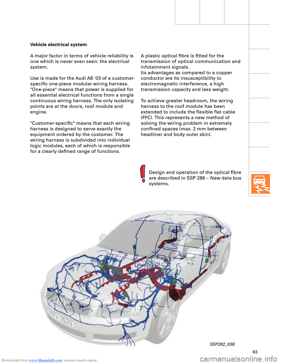
Vehicle electrical system
A major factor in terms of vehicle reliability is
one which is never even seen: the electrical
system.
Use is made for the Audi A8 ´03 of a customer-
specific one-piece modular wiring harness.
"One-piece" means that power is supplied for
all essential electrical functions from a single
continuous wiring harness. The only isolating
points are at the doors, roof module and
engine.
"Customer-specific" means that each wiring
harness is designed to serve exactly the
equipment ordered by the customer. The
wiring harness is subdivided into individual
logic modules, each of which is responsible
for a clearly defined range of functions.
SSP282_038
Design and operation of the optical fibre
are described in SSP 286 – New data bus
systems. A plastic optical fibre is fitted for the
transmission of optical communication and
infotainment signals.
Its advantages as compared to a copper
conductor are its insusceptibility to
electromagnetic interference, a high
transmission capacity and less weight.
To achieve greater headroom, the wiring
harness to the roof module has been
extended to include the flexible flat cable
(FFC). This represents a new method of
solving the wiring problem in extremely
confined spaces (max. 2 mm between
headliner and body outer skin).
Page 82 of 96

Downloaded from www.Manualslib.com manuals search engine 82
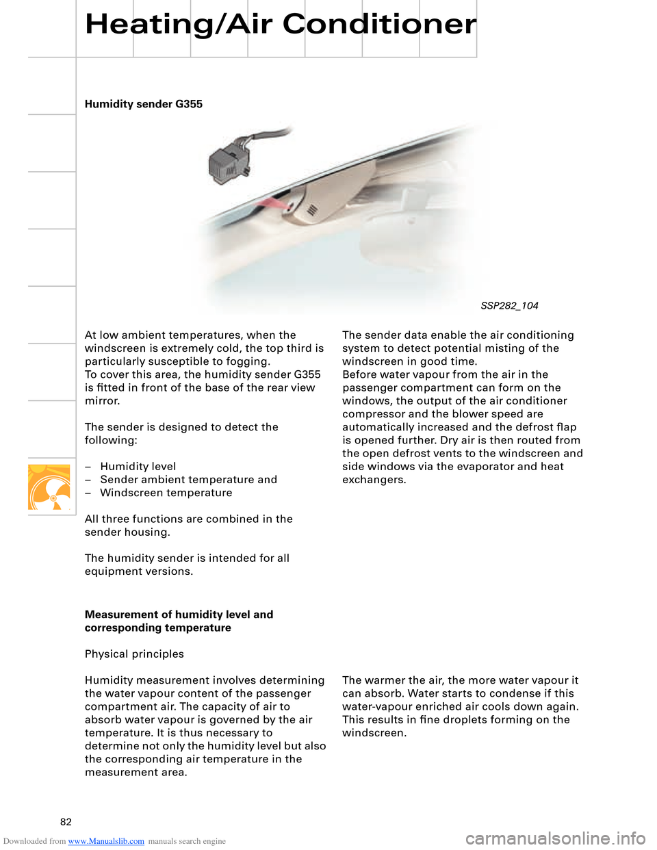
Humidity sender G355
Heating/Air Conditioner
At low ambient temperatures, when the
windscreen is extremely cold, the top third is
particularly susceptible to fogging.
To cover this area, the humidity sender G355
is fitted in front of the base of the rear view
mirror.
The sender is designed to detect the
following:
– Humidity level
– Sender ambient temperature and
– Windscreen temperature
All three functions are combined in the
sender housing.
The humidity sender is intended for all
equipment versions.The sender data enable the air conditioning
system to detect potential misting of the
windscreen in good time.
Before water vapour from the air in the
passenger compartment can form on the
windows, the output of the air conditioner
compressor and the blower speed are
automatically increased and the defrost flap
is opened further. Dry air is then routed from
the open defrost vents to the windscreen and
side windows via the evaporator and heat
exchangers.
Measurement of humidity level and
corresponding temperature
Physical principles
Humidity measurement involves determining
the water vapour content of the passenger
compartment air. The capacity of air to
absorb water vapour is governed by the air
temperature. It is thus necessary to
determine not only the humidity level but also
the corresponding air temperature in the
measurement area.The warmer the air, the more water vapour it
can absorb. Water starts to condense if this
water-vapour enriched air cools down again.
This results in fine droplets forming on the
windscreen.
SSP282_104