2003 AUDI A8 engine oil
[x] Cancel search: engine oilPage 16 of 96
Downloaded from www.Manualslib.com manuals search engine 16
15
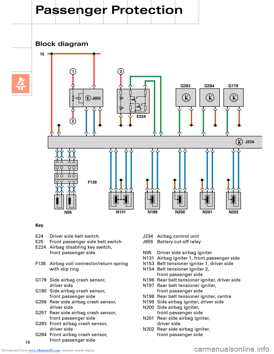
J234
J655
1
2
E224
3
G283G284G179
N131
F138
N202N199N200N201N95
Key
E24 Driver side belt switch
E25 Front passenger side belt switch
E224 Airbag disabling key switch,
front passenger side
F138 Airbag coil connector/return spring
with slip ring
G179 Side airbag crash sensor,
driver side
G180 Side airbag crash sensor,
front passenger side
G256 Rear side airbag crash sensor,
driver side
G257 Rear side airbag crash sensor,
front passenger side
G283 Front airbag crash sensor,
driver side
G284 Front airbag crash sensor,
front passenger side
Block diagram
Passenger Protection
J234 Airbag control unit
J655 Battery cut-off relay
N95 Driver side airbag igniter
N131 Airbag igniter 1, front passenger side
N153 Belt tensioner igniter 1, driver side
N154 Belt tensioner igniter 2,
front passenger side
N196 Rear belt tensioner igniter, driver side
N197 Rear belt tensioner igniter,
front passenger side
N198 Rear belt tensioner igniter, centre
N199 Side airbag igniter, driver side
N200 Side airbag igniter,
front passenger side
N201 Rear side airbag igniter,
driver side
N202 Rear side airbag igniter,
front passenger side
Page 23 of 96
Downloaded from www.Manualslib.com manuals search engine 23
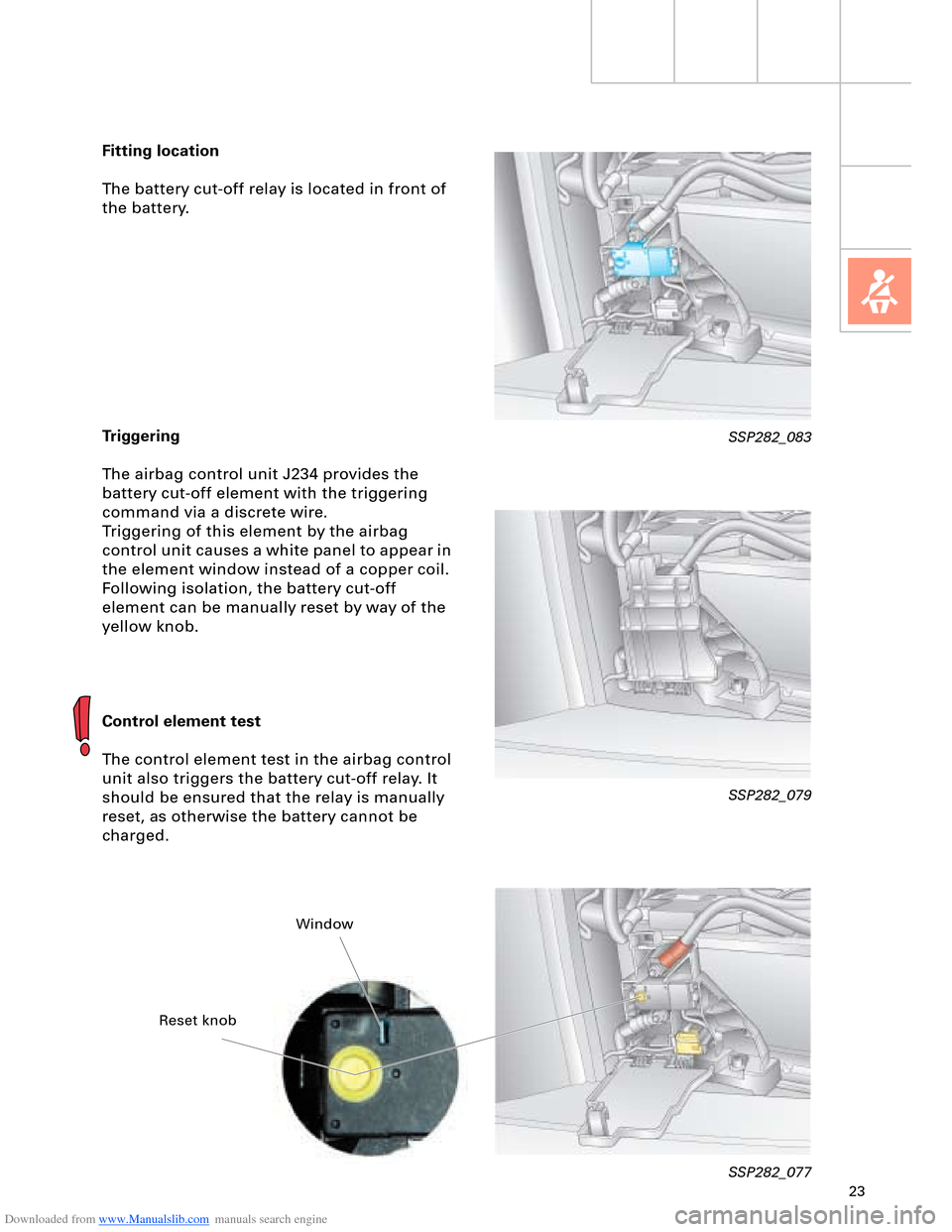
Fitting location
The battery cut-off relay is located in front of
the battery.
Triggering
The airbag control unit J234 provides the
battery cut-off element with the triggering
command via a discrete wire.
Triggering of this element by the airbag
control unit causes a white panel to appear in
the element window instead of a copper coil.
Following isolation, the battery cut-off
element can be manually reset by way of the
yellow knob.
Control element test
The control element test in the airbag control
unit also triggers the battery cut-off relay. It
should be ensured that the relay is manually
reset, as otherwise the battery cannot be
charged.
SSP282_079
SSP282_077
SSP282_083
Reset knobWindow
Page 24 of 96
Downloaded from www.Manualslib.com manuals search engine 24
Engine, Mechanics
200040006000
40
60
80
100
120
140
160
180
200
220
240
260
280 300
320
340 360380 400
420 440
460
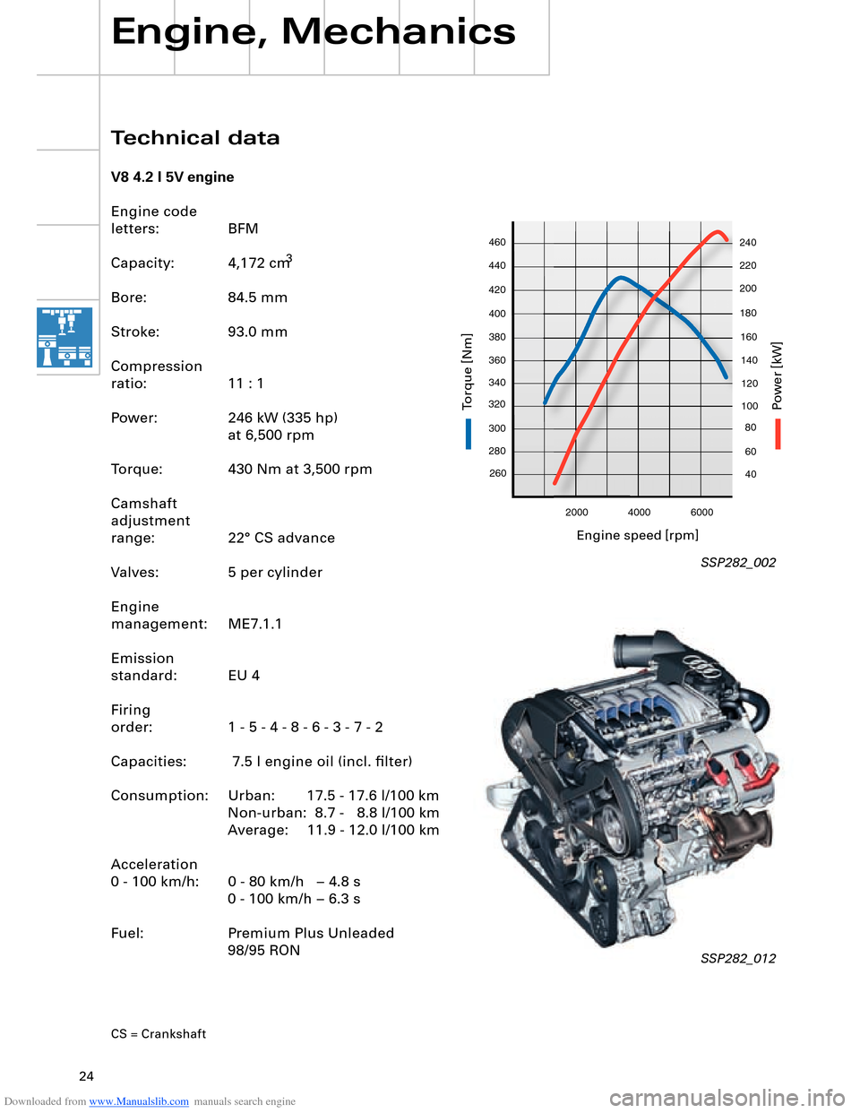
Technical data
V8 4.2 l 5V engine
Engine code
letters: BFM
Capacity:
3
Bore: 84.5 mm
Stroke: 93.0 mm
Compression
ratio: 11 : 1
Power: 246 kW (335 hp)
at 6,500 rpm
Torque: 430 Nm at 3,500 rpm
Camshaft
adjustment
range: 22° CS advance
Valves: 5 per cylinder
Engine
management: ME7.1.1
Emission
standard: EU 4
Firing
order: 1 - 5 - 4 - 8 - 6 - 3 - 7 - 2
Capacities: 7.5 l engine oil (incl. filter)
Consumption: Urban: 17.5 - 17.6 l/100 km Non-urban: 8.7 - 8.8 l/100 km
Average: 11.9 - 12.0 l/100 km
Acceleration
0 - 100 km/h: 0 - 80 km/h – 4.8 s 0 - 100 km/h – 6.3 s
Fuel: Premium Plus Unleaded 98/95 RON
CS = Crankshaft
SSP282_002
SSP282_012
Engine speed [rpm]
P
ower [kW]
T
orq ue [Nm]
4,172 cm
Page 25 of 96

Downloaded from www.Manualslib.com manuals search engine 25
200040006000
260
280 300
320
340 360380 400
420 440
46040
60
80
100
120
140
160
180
200
220
240
V8 3.7 l 5V engine
Engine code
letters: BFL
Capacity:
3
Bore: 84.5 mm
Stroke: 82.4 mm
Compression
ratio: 11 : 1
Power: 206 kW (280 hp)
at 6,000 rpm
Torque: 360 Nm at 3,750 rpm
Camshaft
adjustment
range: 13° CS advance
Valves: 5 per cylinder
Engine
management: ME7.1.1
Emission
standard: EU 4
Firing
order: 1 - 5 - 4 - 8 - 6 - 3 - 7 - 2
Capacities: 7.5 l engine oil (incl. filter)
Consumption: Urban: 17.1 - 17.3 l/100 km Non-urban: 8.6 - 8.8 l/100 km
Average: 11.7 - 11.9 l/100 km
Acceleration
0 - 100 km/h: 0 - 80 km/h – 5.6 s 0 - 100 km/h – 7.3 s
Fuel: Premium Plus Unleaded 98/95 RON
SSP282_001
SSP282_011
Engine speed [rpm]
P
ower [kW]
T
orq ue [Nm]
3,697 cm
Page 30 of 96
Downloaded from www.Manualslib.com manuals search engine 30
Hot-film air-mass meter G70
Engine speed sender G28
Hall sender G40 (bank 2) and
Hall sender 2 G163 (bank 1)
Lambda probe G39
(bank 1)
Lambda probe II G108
(bank 2)
Lambda probe after catalyst G130
(bank 1)
Lambda probe II after catalyst G131
(bank 2)
Throttle valve control
part J338 with
Throttle valve drive G186
(electric power control)
Throttle valve drive angle sender 1 G187
Throttle valve drive angle sender 2 G188
Coolant temperature sender G62
Knock sensor I G61 (bank 1) and
Knock sensor II G66 (bank 2)
Additional signals:
– Air conditioner requirement
– Cruise control switch
– Term. 50, stage 1
– Automatic gearbox selector lever positionEngine control unit J623
Steering
angle sender G85
ESP
control unit J104
Dash panel
insert CANAutomatic
gearbox
control unit J217
Airbag
control unit J234Intake manifold changeover valve
N156 and
Intake manifold changeover valve 2
N261
Left electrohydraulic engine mounting
solenoid valve N144 and
Right electrohydraulic engine mounting
solenoid valve N145
Torque rod valve N382
Lambda probe heater Z19
(bank 1) and
Lambda probe 2 heater Z28
(bank 2)
Lambda probe 1 heater
after catalyst Z29
Lambda probe 2 heater
after catalyst Z30
Additional signals:
– Starter relay term. 50, stage 2
– Tank leakage pump (USA only)
– Air conditioner compressor (out)Fuel pump relay J17
Fuel pump G6
Fuel pump II relay J49
Fuel pump G23
Injectors N30, N31, N32, N33 (bank 1)
Injectors N83, N84, N85, N86 (bank 2)
Ignition coils N (no. 1 cyl.), N128 (no. 2 cyl.),
N158 (no. 3 cyl.), N163 (no. 4 cyl.)
Ignition coils N164 (no. 5 cyl.), N189 (no. 6 cyl.),
N190 (no. 7 cyl.), N191 (no. 8 cyl.)
Activated charcoal filter system solenoid
valve 1 N80
Secondary-air pump relay J299 and
Secondary-air pump motor V101
Secondary air inlet valve N112
Throttle valve control part J338
With throttle valve drive G186
Inlet camshaft timing adjustment valve 1
N205 (bank 1)
and
N208 (bank 2) Pedal position sender/accelerator
pedal module with accelerator pedal
position sender G79 and accelerator
pedal position sender 2 G185
Brake light switch F and
Brake pedal switch F47
Clutch pedal switch F36
(manual gearbox only)
Control unit with display in dash
panel insert J285Data bus diagnostic
interface J533
Engine, Mechanics
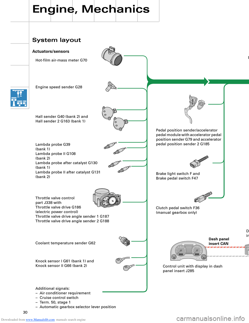
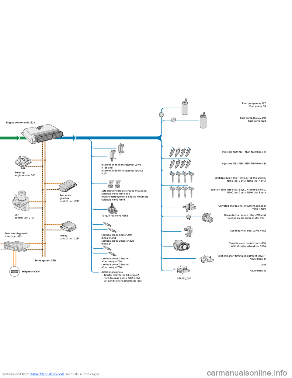
System layout
Actuators/sensors
SSP282_091 Drive system CAN
Diagnosis CAN
Page 31 of 96
Downloaded from www.Manualslib.com manuals search engine 30
Hot-film air-mass meter G70
Engine speed sender G28
Hall sender G40 (bank 2) and
Hall sender 2 G163 (bank 1)
Lambda probe G39
(bank 1)
Lambda probe II G108
(bank 2)
Lambda probe after catalyst G130
(bank 1)
Lambda probe II after catalyst G131
(bank 2)
Throttle valve control
part J338 with
Throttle valve drive G186
(electric power control)
Throttle valve drive angle sender 1 G187
Throttle valve drive angle sender 2 G188
Coolant temperature sender G62
Knock sensor I G61 (bank 1) and
Knock sensor II G66 (bank 2)
Additional signals:
– Air conditioner requirement
– Cruise control switch
– Term. 50, stage 1
– Automatic gearbox selector lever positionEngine control unit J623
Steering
angle sender G85
ESP
control unit J104
Dash panel
insert CANAutomatic
gearbox
control unit J217
Airbag
control unit J234Intake manifold changeover valve
N156 and
Intake manifold changeover valve 2
N261
Left electrohydraulic engine mounting
solenoid valve N144 and
Right electrohydraulic engine mounting
solenoid valve N145
Torque rod valve N382
Lambda probe heater Z19
(bank 1) and
Lambda probe 2 heater Z28
(bank 2)
Lambda probe 1 heater
after catalyst Z29
Lambda probe 2 heater
after catalyst Z30
Additional signals:
– Starter relay term. 50, stage 2
– Tank leakage pump (USA only)
– Air conditioner compressor (out)Fuel pump relay J17
Fuel pump G6
Fuel pump II relay J49
Fuel pump G23
Injectors N30, N31, N32, N33 (bank 1)
Injectors N83, N84, N85, N86 (bank 2)
Ignition coils N (no. 1 cyl.), N128 (no. 2 cyl.),
N158 (no. 3 cyl.), N163 (no. 4 cyl.)
Ignition coils N164 (no. 5 cyl.), N189 (no. 6 cyl.),
N190 (no. 7 cyl.), N191 (no. 8 cyl.)
Activated charcoal filter system solenoid
valve 1 N80
Secondary-air pump relay J299 and
Secondary-air pump motor V101
Secondary air inlet valve N112
Throttle valve control part J338
With throttle valve drive G186
Inlet camshaft timing adjustment valve 1
N205 (bank 1)
and
N208 (bank 2) Pedal position sender/accelerator
pedal module with accelerator pedal
position sender G79 and accelerator
pedal position sender 2 G185
Brake light switch F and
Brake pedal switch F47
Clutch pedal switch F36
(manual gearbox only)
Control unit with display in dash
panel insert J285Data bus diagnostic
interface J533
Engine, Mechanics
System layout
Actuators/sensors
SSP282_091 Drive system CAN
Diagnosis CAN
Page 39 of 96
Downloaded from www.Manualslib.com manuals search engine 39
Advantages:
– Longer service life thanks to noncontacting
measurement system
– Protection against dirt and deposits
– Low contact currents
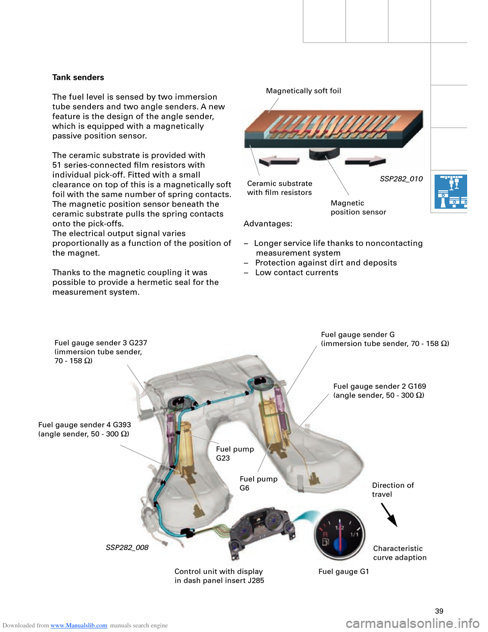
Tank senders
The fuel level is sensed by two immersion
tube senders and two angle senders. A new
feature is the design of the angle sender,
which is equipped with a magnetically
passive position sensor.
The ceramic substrate is provided with
51 series-connected film resistors with
individual pick-off. Fitted with a small
clearance on top of this is a magnetically soft
foil with the same number of spring contacts.
The magnetic position sensor beneath the
ceramic substrate pulls the spring contacts
onto the pick-offs.
The electrical output signal varies
proportionally as a function of the position of
the magnet.
Thanks to the magnetic coupling it was
possible to provide a hermetic seal for the
measurement system.
SSP282_010
SSP282_008
Magnetically soft foil
Ceramic substrate
with film resistors
Magnetic
position sensor
Fuel gauge sender 3 G237
(immersion tube sender,
70 - 158 W)
Fuel gauge sender 4 G393
(angle sender, 50 - 300 W)Fuel gauge sender G
(immersion tube sender, 70 - 158 W)
Fuel gauge sender 2 G169
(angle sender, 50 - 300 W)
Characteristic
curve adaption Direction of
travel
Control unit with display
in dash panel insert J285Fuel gauge G1 Fuel pump
G23
Fuel pump
G6
Page 45 of 96

Downloaded from www.Manualslib.com manuals search engine 45
Two different versions are available:
– 420 Nm for the V8 5V 4.2 l or
3.7 l engine and
– 600 Nm for the V8 TDI 4.0 l or
6.0 l W12 engine To satisfy high comfort requirements, the
Audi A8 ´03 features a new 6-speed automatic
gearbox capable of handling a high engine
torque of max. 600 Nm.
Gearbox
Design and operation of the 09E gearbox
are described in SSP 283 (Part 1) and
SSP 284 (Part 2).
SSP282_043
Technical data
Designation: 09E
Factory
designation: AL 600-6Q
ZF
designation: 6HP-26 A61
Type: 6-speed planetary
gearbox, featuring electro-
hydraulic control
with hydrodynamic
torque converter and
slip-controlled lock-
up clutch
Control: Via mechatronic system
(integration of hydraulic
control unit and
electronic control
to form one unit)Max. torque
transmission: 420 Nm for
V8 5V 4.2 l /3.7 l engine
600 Nm for
V8 TDI 4.0 l /W12
6.0 l engine
Front/rear axle
torque distribution: 50/50
Gear oil capacity
(total): 10.4 litres ATF
Gear oil capacity
(replacement): 10 litres ATF
Total weight: approx. 138 kg
(420 Nm version)
approx. 142 kg
(600 Nm version)