Page 42 of 96

Downloaded from www.Manualslib.com manuals search engine 42
Engine, Mechanics
Sequence of operations
1 Entry and start authorisation switch E415/entry and start authorisation button E408
2 Entry and start authorisation control unit J518
The entry and start authorisation control
unit checks for authorisation – in the form
of information on selector slide position N
or P – from the automatic gearbox control
unit J217 and for brake application in the
case of a start signal from the entry and
start authorisation button E408.
3 Engine control unit J623 Application of selector slide position P/N or
"clutch pressed" information to the engine
control unit (separate interface) causes the
two starter relays J53 and J695 to be
actuated simultaneously. The relays then
switch terminal 50 for starter actuation.
The starter operates and cranks the engine.
On exceeding a defined engine speed, the
engine control unit J623 recognises that
the engine has started and the relays are
deenergised (thus terminating starting
process).
As a safeguard, two relays are connected in
series. In the event of fusion welding of the
make contacts (relay remains closed
following deenergisation), the engine
control unit J623 can thus interrupt the
circuit (terminal 50) by way of the other
relay in each case.
The two relays are deenergised alternately
in order to ensure even make contact wear
(break spark) in both relays. The
deenergisation sequence alternates. The driver triggers a brief start signal
(min. 20 ms) by turning the ignition key to
start position or by pressing the entry and
start authorisation button E408.
If the start prerequisites have been
satisfied, the entry and start authorisation
control unit J518 transmits a start request
– terminal 50 ON – to the engine control
unit J623.
The entry and start authorisation control unit J518 also controls the terminal 15 and
terminal 75x circuits.
Relay operation is monitored and faults diagnosed by evaluating the alternating
deenergisation with the aid of the terminal
50R interface.
The terminal 50R interface represents a link
with terminal 50 and provides the engine
control unit J623 with feedback for start
control/diagnosis.
Automatically controlled starting is not
permitted in the event of undervoltage or a
system fault.
The engine can however be started
manually by way of corresponding start
signal actuation.
To relieve the load on the starter and
battery, the relay actuation time is
limited to approx. 10 seconds per starting
operation (automatic or manual starting).
Page 68 of 96

Downloaded from www.Manualslib.com manuals search engine 68
Electrical System
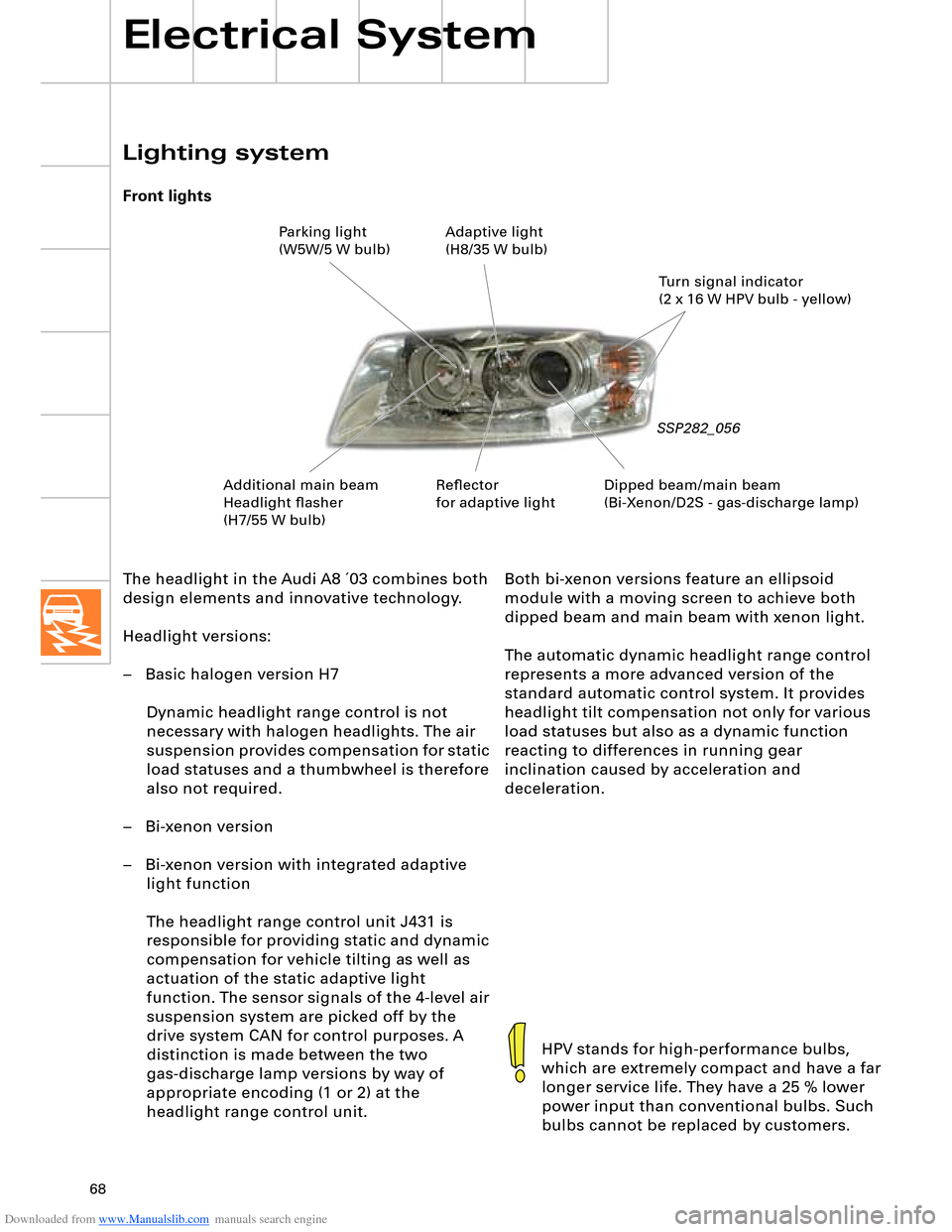
The headlight in the Audi A8 ´03 combines both
design elements and innovative technology.
Headlight versions:
– Basic halogen version H7
Dynamic headlight range control is not
necessary with halogen headlights. The air
suspension provides compensation for static
load statuses and a thumbwheel is therefore
also not required.
– Bi-xenon version
– Bi-xenon version with integrated adaptive
light function
The headlight range control unit J431 is
responsible for providing static and dynamic
compensation for vehicle tilting as well as
actuation of the static adaptive light
function. The sensor signals of the 4-level air
suspension system are picked off by the
drive system CAN for control purposes. A
distinction is made between the two
gas-discharge lamp versions by way of
appropriate encoding (1 or 2) at the
headlight range control unit.
Lighting system
Front lights
SSP282_056
HPV stands for high-performance bulbs,
which are extremely compact and have a far
longer service life. They have a 25 % lower
power input than conventional bulbs. Such
bulbs cannot be replaced by customers.
Both bi-xenon versions feature an ellipsoid
module with a moving screen to achieve both
dipped beam and main beam with xenon light.
The automatic dynamic headlight range control
represents a more advanced version of the
standard automatic control system. It provides
headlight tilt compensation not only for various
load statuses but also as a dynamic function
reacting to differences in running gear
inclination caused by acceleration and
deceleration.
Dipped beam/main beam
(Bi-Xenon/D2S - gas-discharge lamp)Turn signal indicator
(2 x 16 W HPV bulb - yellow) Parking light
(W5W/5 W bulb)Adaptive light
(H8/35 W bulb)
Additional main beam
Headlight flasher
(H7/55 W bulb)Reflector
for adaptive light
Page 69 of 96
Downloaded from www.Manualslib.com manuals search engine 69
Light functions
SSP282_087
Adaptive light
The additional reflector with a 35 W H8
halogen bulb is actuated as the situation
requires to ensure earlier perception of other
road users or obstacles.
When reversing or parking, both adaptive
lights are activated to provide the driver with a
better overall view of the surrounding area.
Adaptive light
Control of the headlight functions is a complex
process.
It involves real time evaluation of several
signals (e.g. vehicle speed, steering angle and
turn signal indicator) by the headlight range
control unit J431.
SSP282_092
The optional headlights with adaptive light
function are a clearly visible innovative feature
in the Audi A8 ´03. To implement this function,
the headlights are provided with an additional
reflector between dipped beam and main
beam.
Page 71 of 96

Downloaded from www.Manualslib.com manuals search engine 71
Rear lights
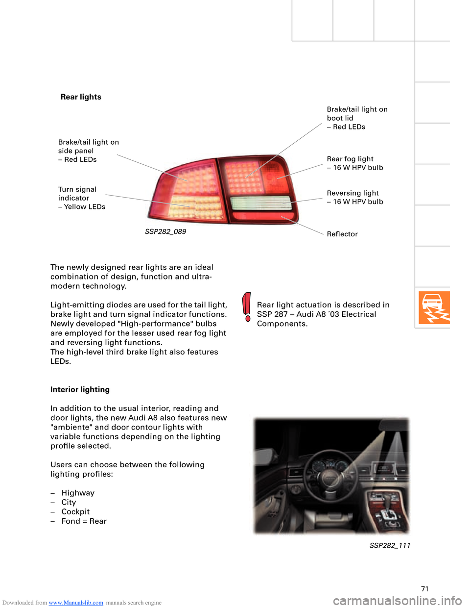
SSP282_089
The newly designed rear lights are an ideal
combination of design, function and ultra-
modern technology.
Light-emitting diodes are used for the tail light,
brake light and turn signal indicator functions.
Newly developed "High-performance" bulbs
are employed for the lesser used rear fog light
and reversing light functions.
The high-level third brake light also features
LEDs.
Interior lighting
In addition to the usual interior, reading and
door lights, the new Audi A8 also features new
"ambiente" and door contour lights with
variable functions depending on the lighting
profile selected.
Users can choose between the following
lighting profiles:
– Highway
– City
– Cockpit
– Fond = Rear
Rear light actuation is described in
SSP 287 – Audi A8 ´03 Electrical
Components.
SSP282_111
Brake/tail light on
side panel
– Red LEDs
Turn signal
indicator
– Yellow LEDsBrake/tail light on
boot lid
– Red LEDs
Rear fog light
– 16 W HPV bulb
Reversing light
– 16 W HPV bulb
Reflector