2003 AUDI A8 Battery
[x] Cancel search: BatteryPage 10 of 96
Downloaded from www.Manualslib.com manuals search engine 10
Body
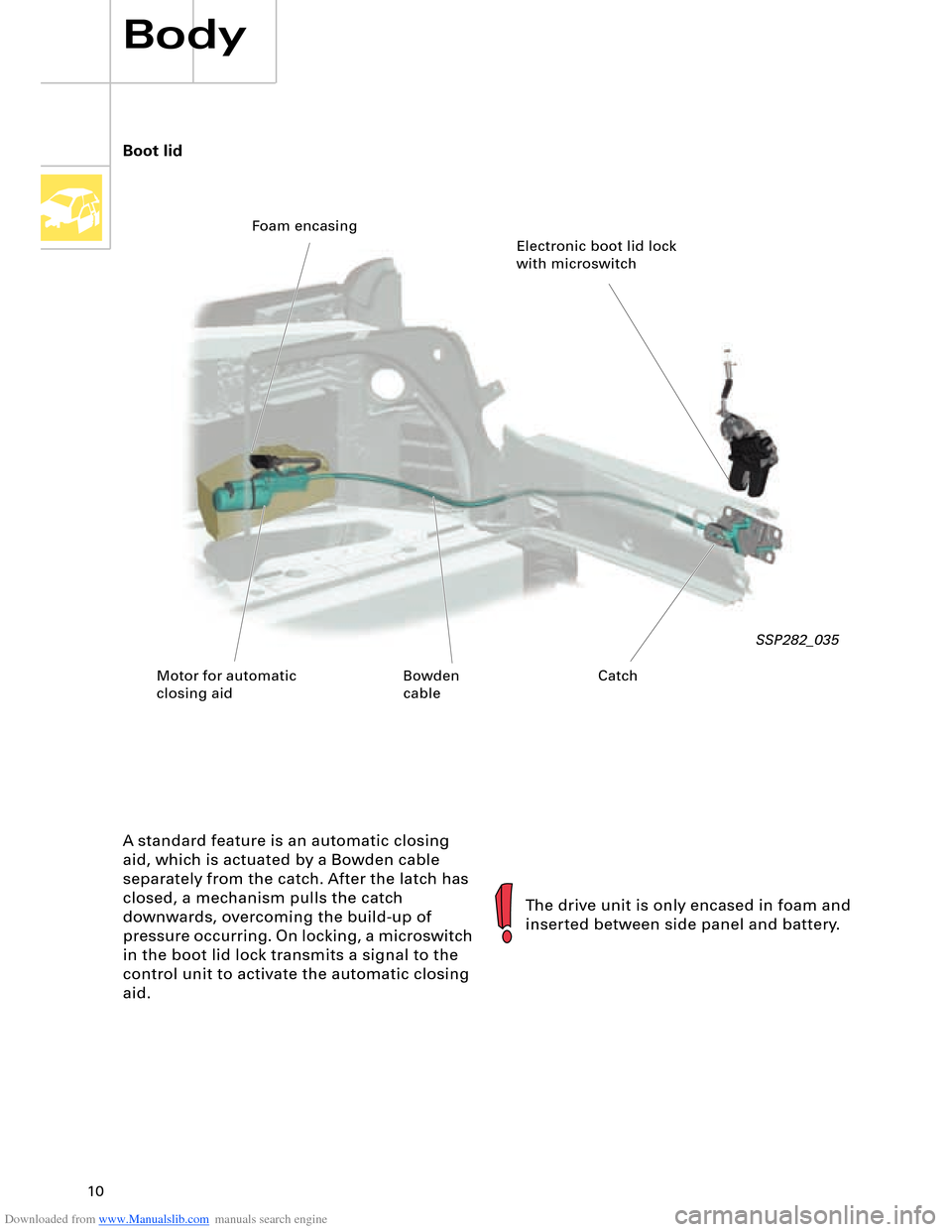
A standard feature is an automatic closing
aid, which is actuated by a Bowden cable
separately from the catch. After the latch has
closed, a mechanism pulls the catch
downwards, overcoming the build-up of
pressure occurring. On locking, a microswitch
in the boot lid lock transmits a signal to the
control unit to activate the automatic closing
aid.
SSP282_035
The drive unit is only encased in foam and
inserted between side panel and battery. Boot lid
Electronic boot lid lock
with microswitch Foam encasing
Motor for automatic
closing aidCatch Bowden
cable
Page 15 of 96
Downloaded from www.Manualslib.com manuals search engine 15
The wide range of sensors permits detection
not only of head-on collision and side impact,
but also of rear-end collisions. Use is made in the Audi A8 ´03 of the 8.4E+
airbag system with the aim of attaining greater
occupant safety whilst reducing the impact.
This was achieved, for example, by way of two-
stage front airbag triggering, active front head
restraints and a battery cut-off element.
K75 Airbag warning lamp
K145 Airbag disabled warning lamp,
front passenger side
N95 Driver side airbag igniter
N131 Airbag igniter 1, front passenger side
N153 Belt tensioner igniter 1, driver side
N154 Belt tensioner igniter 2,
front passenger side
N196 Rear belt tensioner igniter,
driver side
N197 Rear belt tensioner igniter,
front passenger side
N198 Rear belt tensioner igniter,
centre
N199 Side airbag igniter, driver side
N200 Side airbag igniter,
front passenger side
N201 Rear side airbag igniter,
driver side
N202 Rear side airbag igniter,
front passenger side
N251 Curtain airbag igniter, driver side
N252 Curtain airbag igniter,
front passenger side
T16 16-pin connector
(diagnostic connection) Key
E24 Driver side belt switch
E25 Front passenger side belt switch
E224 Airbag disabling key switch,
front passenger side
G85 Steering angle sender
G179 Side airbag crash sensor,
driver side (B-pillar)
G180 Side airbag crash sensor,
front passenger side (B-pillar)
G256 Rear side airbag crash sensor,
driver side
G257 Rear side airbag crash sensor,
front passenger side
G283 Front airbag crash sensor,
driver side
G284 Front airbag crash sensor,
front passenger side
J234 Airbag control unit
J285 Control unit with display
in dash panel insert
J393 Convenience system central
control unit
J526 Telephone/telematics control unit
J533 Data bus diagnostic interface
(gateway)
J623 Engine control unit
J655 Battery cut-off relay
Page 16 of 96
Downloaded from www.Manualslib.com manuals search engine 16
15
J234
J655
1
2
E224
3
G283G284G179
N131
F138
N202N199N200N201N95
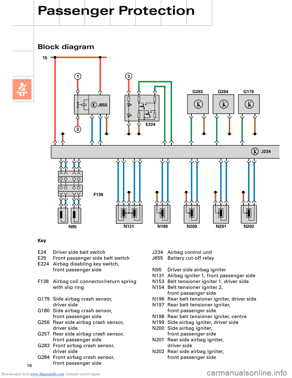
Key
E24 Driver side belt switch
E25 Front passenger side belt switch
E224 Airbag disabling key switch,
front passenger side
F138 Airbag coil connector/return spring
with slip ring
G179 Side airbag crash sensor,
driver side
G180 Side airbag crash sensor,
front passenger side
G256 Rear side airbag crash sensor,
driver side
G257 Rear side airbag crash sensor,
front passenger side
G283 Front airbag crash sensor,
driver side
G284 Front airbag crash sensor,
front passenger side
Block diagram
Passenger Protection
J234 Airbag control unit
J655 Battery cut-off relay
N95 Driver side airbag igniter
N131 Airbag igniter 1, front passenger side
N153 Belt tensioner igniter 1, driver side
N154 Belt tensioner igniter 2,
front passenger side
N196 Rear belt tensioner igniter, driver side
N197 Rear belt tensioner igniter,
front passenger side
N198 Rear belt tensioner igniter, centre
N199 Side airbag igniter, driver side
N200 Side airbag igniter,
front passenger side
N201 Rear side airbag igniter,
driver side
N202 Rear side airbag igniter,
front passenger side
Page 17 of 96
Downloaded from www.Manualslib.com manuals search engine 17
4567
G256G257E24E25
N198N251N252N153N154N196N197
G180
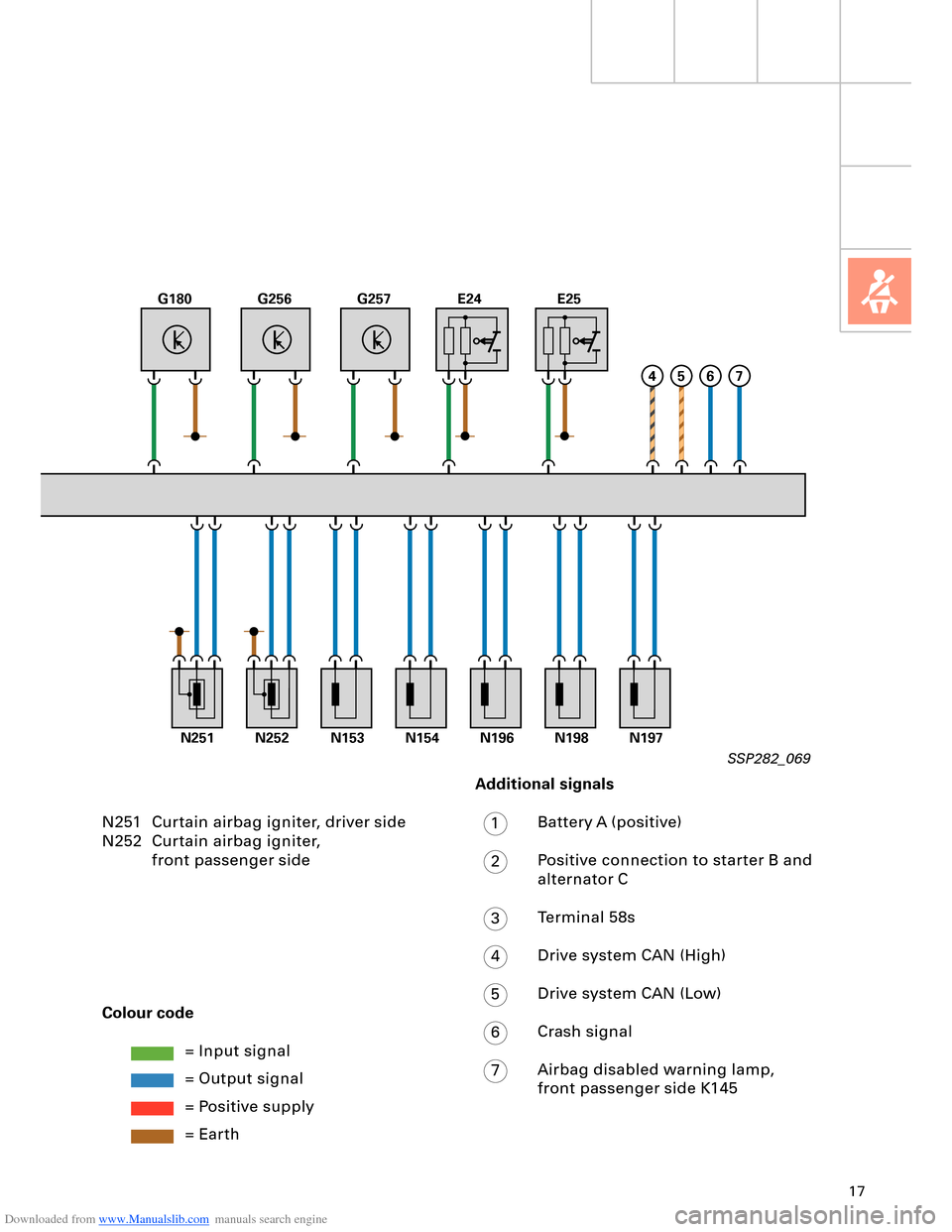
N251 Curtain airbag igniter, driver side
N252 Curtain airbag igniter,
front passenger side
Colour code
= Input signal
= Output signal
= Positive supply
= Earth
Additional signals
Battery A (positive)
Positive connection to starter B and
alternator C
Terminal 58s
Drive system CAN (High)
Drive system CAN (Low)
Crash signal
Airbag disabled warning lamp,
front passenger side K145
1
2
3
4
5
6
7
SSP282_069
Page 22 of 96
Downloaded from www.Manualslib.com manuals search engine 22
Passenger Protection
15 30
+
-
31
J644
J655
43
B
1
2
A
TerminalPinInput/outputDescription
30, battery A Input
(screw connection)U
bat. term. 30/battery
87 B Output
(screw connection)Output
Terminal 15 1 Input
(plug connection)Positive power supply,
interruptible
Vehicle earth 2 Input
(plug connection)Earth from
airbag control unit J234
Crash signal 3 Input
(plug connection)Crash signal from
airbag control unit J234
Diagnosis 4 Input
(plug connection)Diagnostic wire from
airbag control unit J234
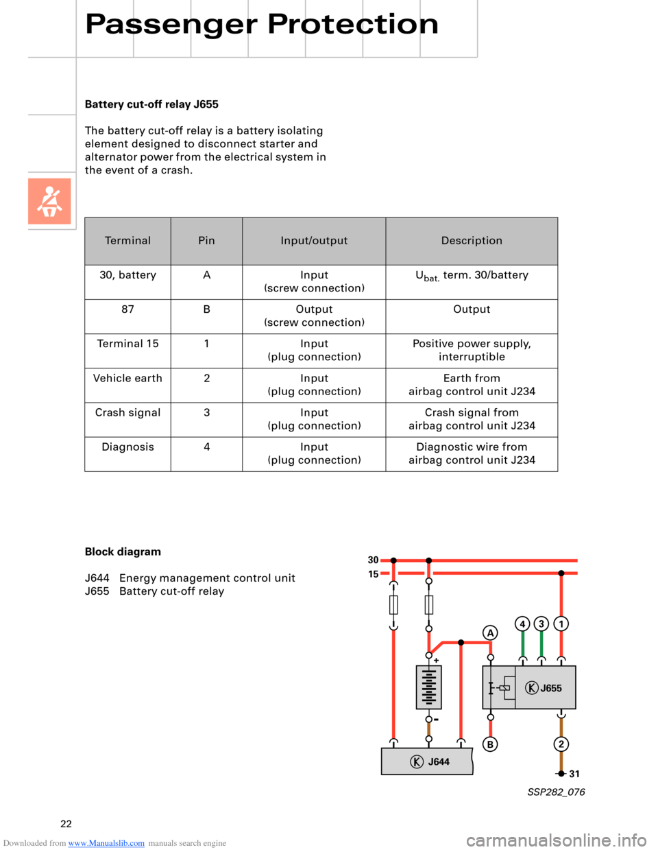
Battery cut-off relay J655
The battery cut-off relay is a battery isolating
element designed to disconnect starter and
alternator power from the electrical system in
the event of a crash.
Block diagram
J644 Energy management control unit
J655 Battery cut-off relay
SSP282_076
Page 23 of 96
Downloaded from www.Manualslib.com manuals search engine 23
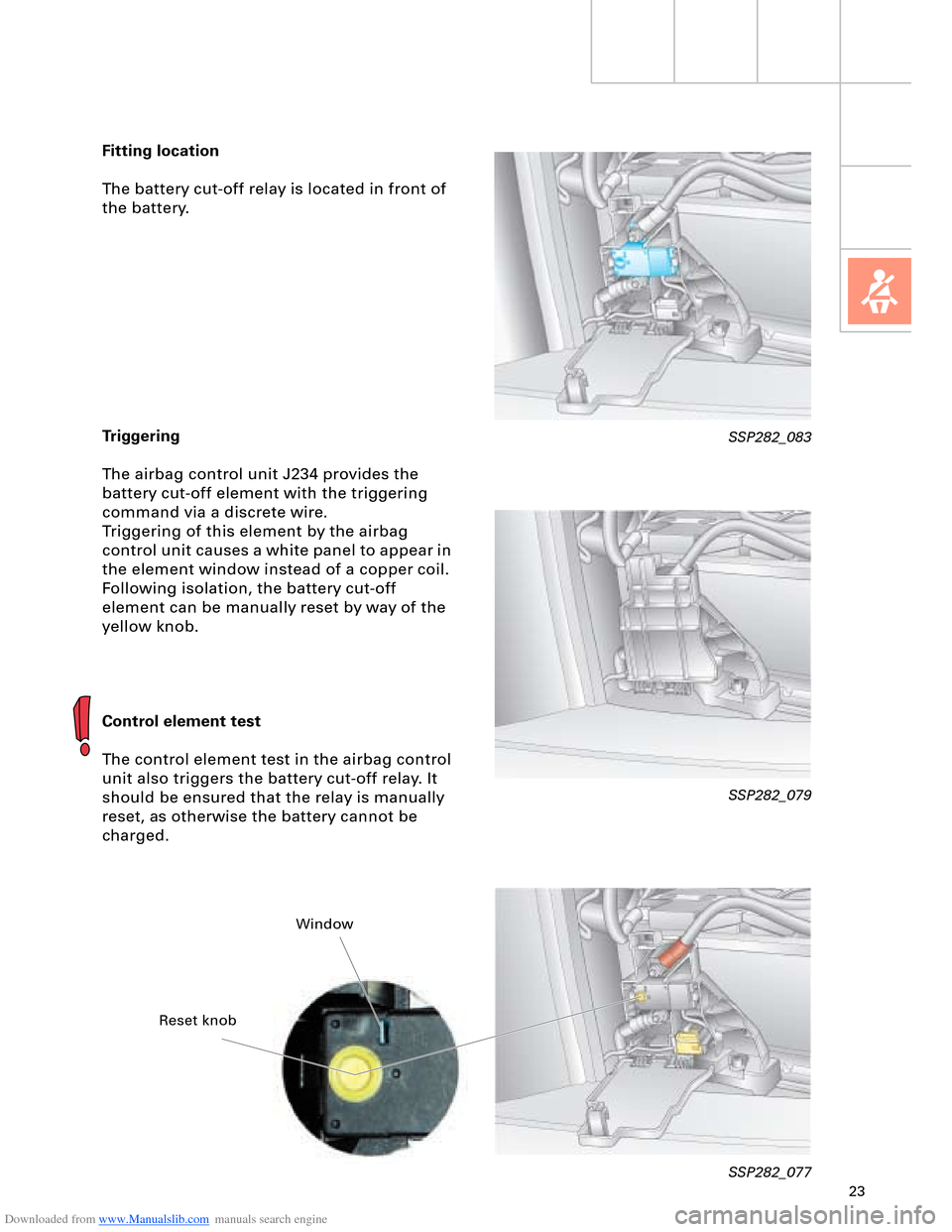
Fitting location
The battery cut-off relay is located in front of
the battery.
Triggering
The airbag control unit J234 provides the
battery cut-off element with the triggering
command via a discrete wire.
Triggering of this element by the airbag
control unit causes a white panel to appear in
the element window instead of a copper coil.
Following isolation, the battery cut-off
element can be manually reset by way of the
yellow knob.
Control element test
The control element test in the airbag control
unit also triggers the battery cut-off relay. It
should be ensured that the relay is manually
reset, as otherwise the battery cannot be
charged.
SSP282_079
SSP282_077
SSP282_083
Reset knobWindow
Page 42 of 96
Downloaded from www.Manualslib.com manuals search engine 42
Engine, Mechanics
Sequence of operations
1 Entry and start authorisation switch E415/entry and start authorisation button E408
2 Entry and start authorisation control unit J518
The entry and start authorisation control
unit checks for authorisation – in the form
of information on selector slide position N
or P – from the automatic gearbox control
unit J217 and for brake application in the
case of a start signal from the entry and
start authorisation button E408.
3 Engine control unit J623 Application of selector slide position P/N or
"clutch pressed" information to the engine
control unit (separate interface) causes the
two starter relays J53 and J695 to be
actuated simultaneously. The relays then
switch terminal 50 for starter actuation.
The starter operates and cranks the engine.
On exceeding a defined engine speed, the
engine control unit J623 recognises that
the engine has started and the relays are
deenergised (thus terminating starting
process).
As a safeguard, two relays are connected in
series. In the event of fusion welding of the
make contacts (relay remains closed
following deenergisation), the engine
control unit J623 can thus interrupt the
circuit (terminal 50) by way of the other
relay in each case.
The two relays are deenergised alternately
in order to ensure even make contact wear
(break spark) in both relays. The
deenergisation sequence alternates. The driver triggers a brief start signal
(min. 20 ms) by turning the ignition key to
start position or by pressing the entry and
start authorisation button E408.
If the start prerequisites have been
satisfied, the entry and start authorisation
control unit J518 transmits a start request
– terminal 50 ON – to the engine control
unit J623.
The entry and start authorisation control unit J518 also controls the terminal 15 and
terminal 75x circuits.
Relay operation is monitored and faults diagnosed by evaluating the alternating
deenergisation with the aid of the terminal
50R interface.
The terminal 50R interface represents a link
with terminal 50 and provides the engine
control unit J623 with feedback for start
control/diagnosis.
Automatically controlled starting is not
permitted in the event of undervoltage or a
system fault.
The engine can however be started
manually by way of corresponding start
signal actuation.
To relieve the load on the starter and
battery, the relay actuation time is
limited to approx. 10 seconds per starting
operation (automatic or manual starting).
Page 48 of 96
Downloaded from www.Manualslib.com manuals search engine 48
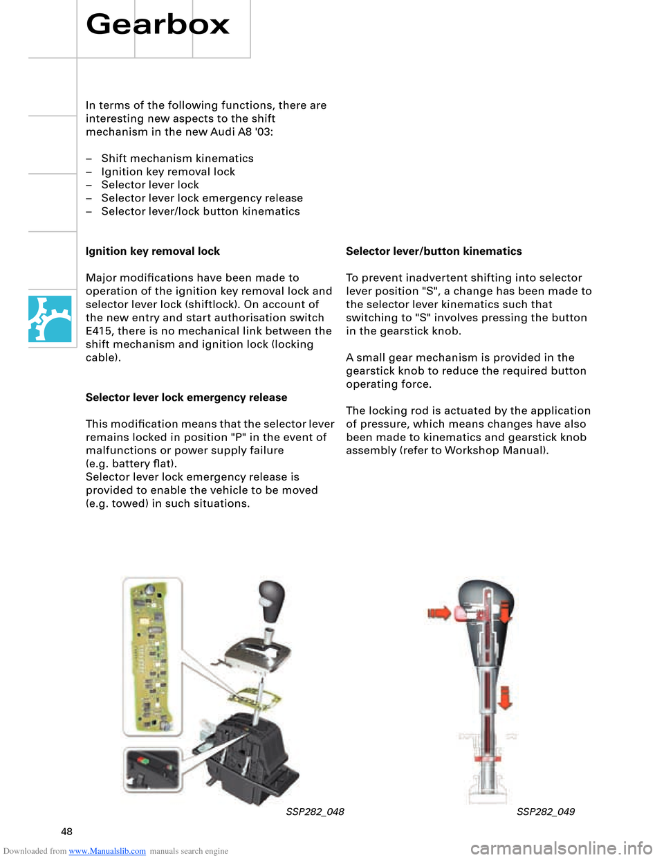
Selector lever/button kinematics
To prevent inadvertent shifting into selector
lever position "S", a change has been made to
the selector lever kinematics such that
switching to "S" involves pressing the button
in the gearstick knob.
A small gear mechanism is provided in the
gearstick knob to reduce the required button
operating force.
The locking rod is actuated by the application
of pressure, which means changes have also
been made to kinematics and gearstick knob
assembly (refer to Workshop Manual).
In terms of the following functions, there are
interesting new aspects to the shift
mechanism in the new Audi A8 '03:
– Shift mechanism kinematics
– Ignition key removal lock
– Selector lever lock
– Selector lever lock emergency release
– Selector lever/lock button kinematics
Ignition key removal lock
Major modifications have been made to
operation of the ignition key removal lock and
selector lever lock (shiftlock). On account of
the new entry and start authorisation switch
E415, there is no mechanical link between the
shift mechanism and ignition lock (locking
cable).
Selector lever lock emergency release
This modification means that the selector lever
remains locked in position "P" in the event of
malfunctions or power supply failure
(e.g. battery flat).
Selector lever lock emergency release is
provided to enable the vehicle to be moved
(e.g. towed) in such situations.
Gearbox
SSP282_048 SSP282_049