2003 AUDI A8 cruise control
[x] Cancel search: cruise controlPage 2 of 96
Downloaded from www.Manualslib.com manuals search engine Complete vehicle information
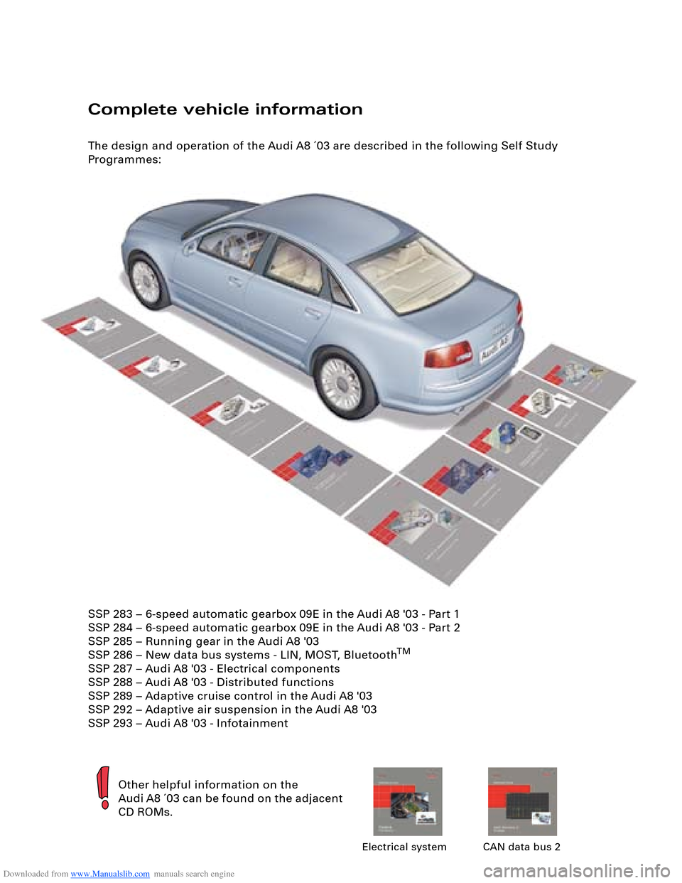
The design and operation of the Audi A8 ´03 are described in the following Self Study
Programmes:
Other helpful information on the
Audi A8 ´03 can be found on the adjacent
CD ROMs.
Electrical system CAN data bus 2
SSP 283 – 6-speed automatic gearbox 09E in the Audi A8 '03 - Part 1
SSP 284 – 6-speed automatic gearbox 09E in the Audi A8 '03 - Part 2
SSP 285 – Running gear in the Audi A8 '03
SSP 286 – New data bus systems - LIN, MOST, Bluetooth
TM
SSP 287 – Audi A8 '03 - Electrical components
SSP 288 – Audi A8 '03 - Distributed functions
SSP 289 – Adaptive cruise control in the Audi A8 '03
SSP 292 – Adaptive air suspension in the Audi A8 '03
SSP 293 – Audi A8 '03 - Infotainment
Page 3 of 96
Downloaded from www.Manualslib.com manuals search engine 3
Attention
NoteNew
Contents
Page
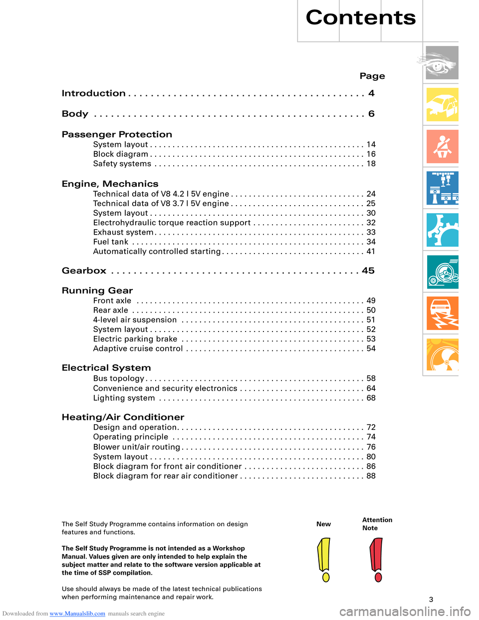
Introduction . . . . . . . . . . . . . . . . . . . . . . . . . . . . . . . . . . . . . . . . . . 4
Body . . . . . . . . . . . . . . . . . . . . . . . . . . . . . . . . . . . . . . . . . . . . . . . . 6
Passenger Protection
System layout . . . . . . . . . . . . . . . . . . . . . . . . . . . . . . . . . . . . . . . . . . . . . . . . 14
Block diagram . . . . . . . . . . . . . . . . . . . . . . . . . . . . . . . . . . . . . . . . . . . . . . . . 16
Safety systems . . . . . . . . . . . . . . . . . . . . . . . . . . . . . . . . . . . . . . . . . . . . . . . 18
Engine, Mechanics
Technical data of V8 4.2 l 5V engine . . . . . . . . . . . . . . . . . . . . . . . . . . . . . . 24
Technical data of V8 3.7 l 5V engine . . . . . . . . . . . . . . . . . . . . . . . . . . . . . . 25
System layout . . . . . . . . . . . . . . . . . . . . . . . . . . . . . . . . . . . . . . . . . . . . . . . . 30
Electrohydraulic torque reaction support . . . . . . . . . . . . . . . . . . . . . . . . . 32
Exhaust system . . . . . . . . . . . . . . . . . . . . . . . . . . . . . . . . . . . . . . . . . . . . . . . 33
Fuel tank . . . . . . . . . . . . . . . . . . . . . . . . . . . . . . . . . . . . . . . . . . . . . . . . . . . . 34
Automatically controlled starting . . . . . . . . . . . . . . . . . . . . . . . . . . . . . . . . 41
Gearbox . . . . . . . . . . . . . . . . . . . . . . . . . . . . . . . . . . . . . . . . . . . . 45
Running Gear
Front axle . . . . . . . . . . . . . . . . . . . . . . . . . . . . . . . . . . . . . . . . . . . . . . . . . . . 49
Rear axle . . . . . . . . . . . . . . . . . . . . . . . . . . . . . . . . . . . . . . . . . . . . . . . . . . . . 50
4-level air suspension . . . . . . . . . . . . . . . . . . . . . . . . . . . . . . . . . . . . . . . . . 51
System layout . . . . . . . . . . . . . . . . . . . . . . . . . . . . . . . . . . . . . . . . . . . . . . . . 52
Electric parking brake . . . . . . . . . . . . . . . . . . . . . . . . . . . . . . . . . . . . . . . . . 53
Adaptive cruise control . . . . . . . . . . . . . . . . . . . . . . . . . . . . . . . . . . . . . . . . 54
Electrical System
Bus topology . . . . . . . . . . . . . . . . . . . . . . . . . . . . . . . . . . . . . . . . . . . . . . . . . 58
Convenience and security electronics . . . . . . . . . . . . . . . . . . . . . . . . . . . . 64
Lighting system . . . . . . . . . . . . . . . . . . . . . . . . . . . . . . . . . . . . . . . . . . . . . . 68
Heating/Air Conditioner
Design and operation. . . . . . . . . . . . . . . . . . . . . . . . . . . . . . . . . . . . . . . . . . 72
Operating principle . . . . . . . . . . . . . . . . . . . . . . . . . . . . . . . . . . . . . . . . . . . 74
Blower unit/air routing . . . . . . . . . . . . . . . . . . . . . . . . . . . . . . . . . . . . . . . . . 76
System layout . . . . . . . . . . . . . . . . . . . . . . . . . . . . . . . . . . . . . . . . . . . . . . . . 80
Block diagram for front air conditioner . . . . . . . . . . . . . . . . . . . . . . . . . . . 86
Block diagram for rear air conditioner . . . . . . . . . . . . . . . . . . . . . . . . . . . . 88
The Self Study Programme contains information on design
features and functions.
The Self Study Programme is not intended as a Workshop
Manual. Values given are only intended to help explain the
subject matter and relate to the software version applicable at
the time of SSP compilation.
Use should always be made of the latest technical publications
when performing maintenance and repair work.
Page 4 of 96
Downloaded from www.Manualslib.com manuals search engine 4
Introduction
The new Audi A8 is designed to replace its
predecessor of the same name which achieved
a total production figure of 105,092 since its
introduction in June 1994. This was the first
standard saloon with aluminium body and
epitomised a new philosophy in the luxury
vehicle sector.
The weight-saving Audi Space Frame ASF
represented a major breakthrough in terms of
enhanced vehicle dynamics, whilst at the same
time solving the problem of increasing weight.
Introduction
This body concept was further perfected in
the Audi A2 and the design of the Audi A8 ´03
reflects the experience gained from both
projects.
The aim when developing the Audi A8 ´03 was
not merely to surpass its predecessor in
terms of technical features and details.
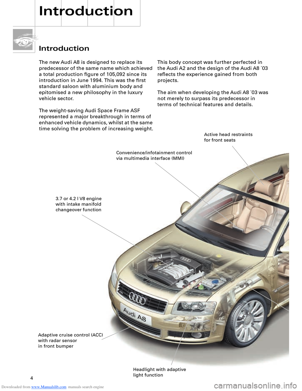
Convenience/infotainment control
via multimedia interface (MMI)
3.7 or 4.2 l V8 engine
with intake manifold
changeover function
Adaptive cruise control (ACC)
with radar sensor
in front bumper
Headlight with adaptive
light functionActive head restraints
for front seats
Page 30 of 96
Downloaded from www.Manualslib.com manuals search engine 30
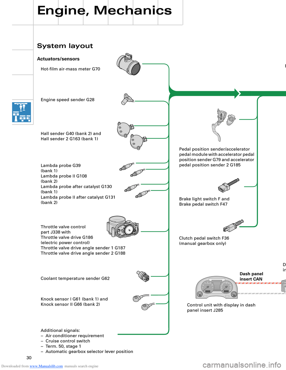
Hot-film air-mass meter G70
Engine speed sender G28
Hall sender G40 (bank 2) and
Hall sender 2 G163 (bank 1)
Lambda probe G39
(bank 1)
Lambda probe II G108
(bank 2)
Lambda probe after catalyst G130
(bank 1)
Lambda probe II after catalyst G131
(bank 2)
Throttle valve control
part J338 with
Throttle valve drive G186
(electric power control)
Throttle valve drive angle sender 1 G187
Throttle valve drive angle sender 2 G188
Coolant temperature sender G62
Knock sensor I G61 (bank 1) and
Knock sensor II G66 (bank 2)
Additional signals:
– Air conditioner requirement
– Cruise control switch
– Term. 50, stage 1
– Automatic gearbox selector lever positionEngine control unit J623
Steering
angle sender G85
ESP
control unit J104
Dash panel
insert CANAutomatic
gearbox
control unit J217
Airbag
control unit J234Intake manifold changeover valve
N156 and
Intake manifold changeover valve 2
N261
Left electrohydraulic engine mounting
solenoid valve N144 and
Right electrohydraulic engine mounting
solenoid valve N145
Torque rod valve N382
Lambda probe heater Z19
(bank 1) and
Lambda probe 2 heater Z28
(bank 2)
Lambda probe 1 heater
after catalyst Z29
Lambda probe 2 heater
after catalyst Z30
Additional signals:
– Starter relay term. 50, stage 2
– Tank leakage pump (USA only)
– Air conditioner compressor (out)Fuel pump relay J17
Fuel pump G6
Fuel pump II relay J49
Fuel pump G23
Injectors N30, N31, N32, N33 (bank 1)
Injectors N83, N84, N85, N86 (bank 2)
Ignition coils N (no. 1 cyl.), N128 (no. 2 cyl.),
N158 (no. 3 cyl.), N163 (no. 4 cyl.)
Ignition coils N164 (no. 5 cyl.), N189 (no. 6 cyl.),
N190 (no. 7 cyl.), N191 (no. 8 cyl.)
Activated charcoal filter system solenoid
valve 1 N80
Secondary-air pump relay J299 and
Secondary-air pump motor V101
Secondary air inlet valve N112
Throttle valve control part J338
With throttle valve drive G186
Inlet camshaft timing adjustment valve 1
N205 (bank 1)
and
N208 (bank 2) Pedal position sender/accelerator
pedal module with accelerator pedal
position sender G79 and accelerator
pedal position sender 2 G185
Brake light switch F and
Brake pedal switch F47
Clutch pedal switch F36
(manual gearbox only)
Control unit with display in dash
panel insert J285Data bus diagnostic
interface J533
Engine, Mechanics
System layout
Actuators/sensors
SSP282_091 Drive system CAN
Diagnosis CAN
Page 31 of 96
Downloaded from www.Manualslib.com manuals search engine 30
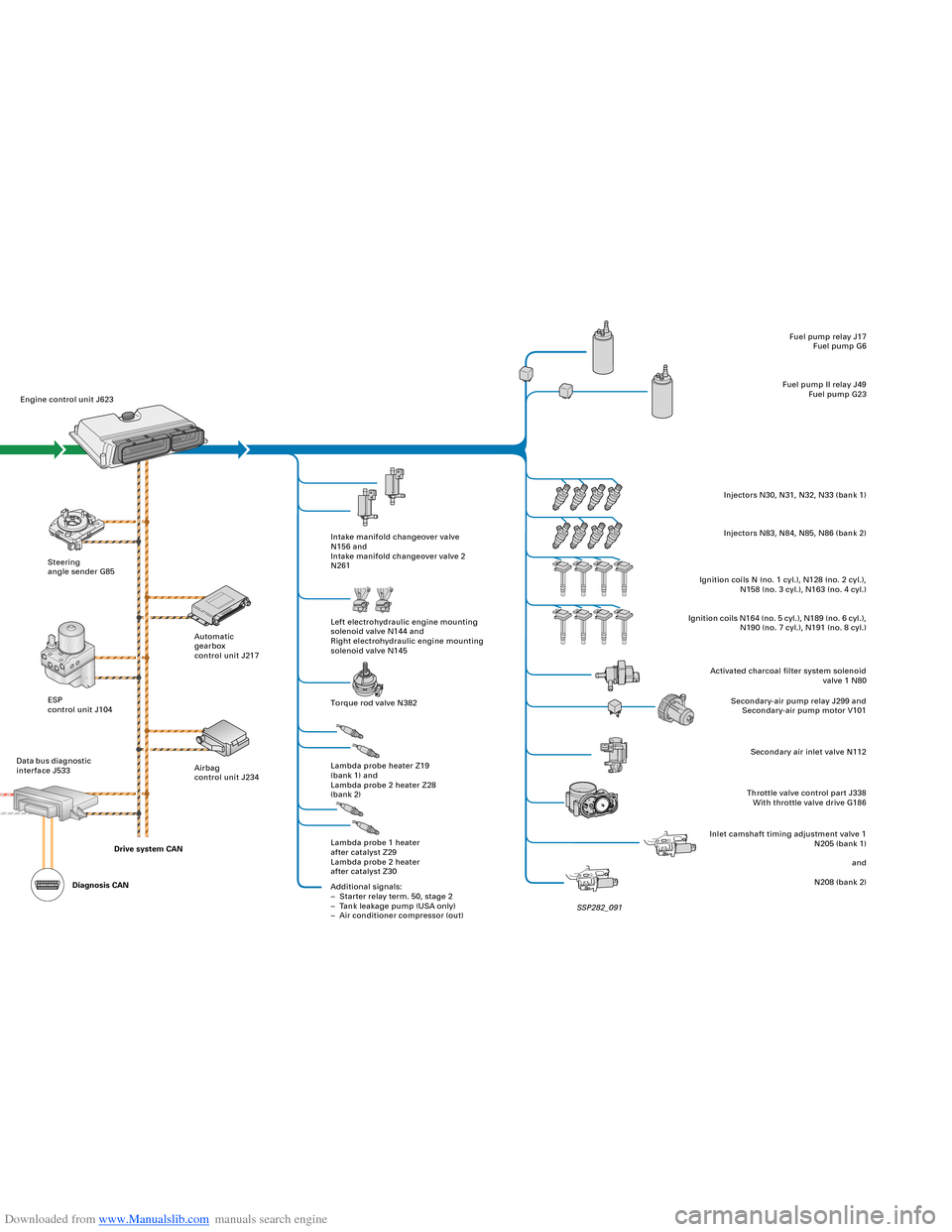
Hot-film air-mass meter G70
Engine speed sender G28
Hall sender G40 (bank 2) and
Hall sender 2 G163 (bank 1)
Lambda probe G39
(bank 1)
Lambda probe II G108
(bank 2)
Lambda probe after catalyst G130
(bank 1)
Lambda probe II after catalyst G131
(bank 2)
Throttle valve control
part J338 with
Throttle valve drive G186
(electric power control)
Throttle valve drive angle sender 1 G187
Throttle valve drive angle sender 2 G188
Coolant temperature sender G62
Knock sensor I G61 (bank 1) and
Knock sensor II G66 (bank 2)
Additional signals:
– Air conditioner requirement
– Cruise control switch
– Term. 50, stage 1
– Automatic gearbox selector lever positionEngine control unit J623
Steering
angle sender G85
ESP
control unit J104
Dash panel
insert CANAutomatic
gearbox
control unit J217
Airbag
control unit J234Intake manifold changeover valve
N156 and
Intake manifold changeover valve 2
N261
Left electrohydraulic engine mounting
solenoid valve N144 and
Right electrohydraulic engine mounting
solenoid valve N145
Torque rod valve N382
Lambda probe heater Z19
(bank 1) and
Lambda probe 2 heater Z28
(bank 2)
Lambda probe 1 heater
after catalyst Z29
Lambda probe 2 heater
after catalyst Z30
Additional signals:
– Starter relay term. 50, stage 2
– Tank leakage pump (USA only)
– Air conditioner compressor (out)Fuel pump relay J17
Fuel pump G6
Fuel pump II relay J49
Fuel pump G23
Injectors N30, N31, N32, N33 (bank 1)
Injectors N83, N84, N85, N86 (bank 2)
Ignition coils N (no. 1 cyl.), N128 (no. 2 cyl.),
N158 (no. 3 cyl.), N163 (no. 4 cyl.)
Ignition coils N164 (no. 5 cyl.), N189 (no. 6 cyl.),
N190 (no. 7 cyl.), N191 (no. 8 cyl.)
Activated charcoal filter system solenoid
valve 1 N80
Secondary-air pump relay J299 and
Secondary-air pump motor V101
Secondary air inlet valve N112
Throttle valve control part J338
With throttle valve drive G186
Inlet camshaft timing adjustment valve 1
N205 (bank 1)
and
N208 (bank 2) Pedal position sender/accelerator
pedal module with accelerator pedal
position sender G79 and accelerator
pedal position sender 2 G185
Brake light switch F and
Brake pedal switch F47
Clutch pedal switch F36
(manual gearbox only)
Control unit with display in dash
panel insert J285Data bus diagnostic
interface J533
Engine, Mechanics
System layout
Actuators/sensors
SSP282_091 Drive system CAN
Diagnosis CAN
Page 54 of 96
Downloaded from www.Manualslib.com manuals search engine 54
Driver convenience is further enhanced, as
fewer accelerator and brake pedal operations
are required. Speed restrictions and safety
factors are reliably observed and the flow of
traffic thus better regulated.
ACC (Adaptive Cruise
Control)
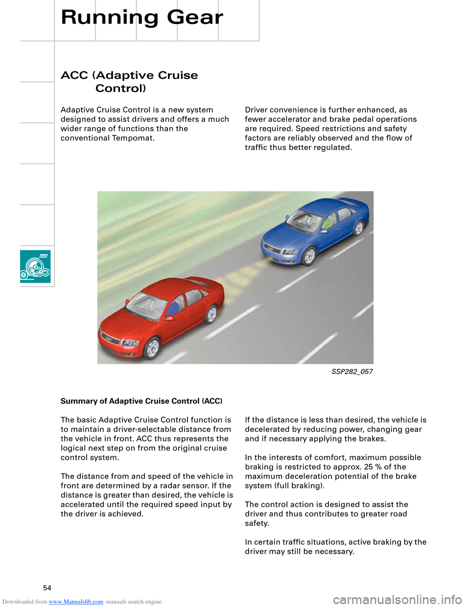
Adaptive Cruise Control is a new system
designed to assist drivers and offers a much
wider range of functions than the
conventional Tempomat.
Running Gear
If the distance is less than desired, the vehicle is
decelerated by reducing power, changing gear
and if necessary applying the brakes.
In the interests of comfort, maximum possible
braking is restricted to approx. 25 % of the
maximum deceleration potential of the brake
system (full braking).
The control action is designed to assist the
driver and thus contributes to greater road
safety.
In certain traffic situations, active braking by the
driver may still be necessary. Summary of Adaptive Cruise Control (ACC)
The basic Adaptive Cruise Control function is
to maintain a driver-selectable distance from
the vehicle in front. ACC thus represents the
logical next step on from the original cruise
control system.
The distance from and speed of the vehicle in
front are determined by a radar sensor. If the
distance is greater than desired, the vehicle is
accelerated until the required speed input by
the driver is achieved.
SSP282_057
Page 56 of 96
Downloaded from www.Manualslib.com manuals search engine 56
SSP282_061
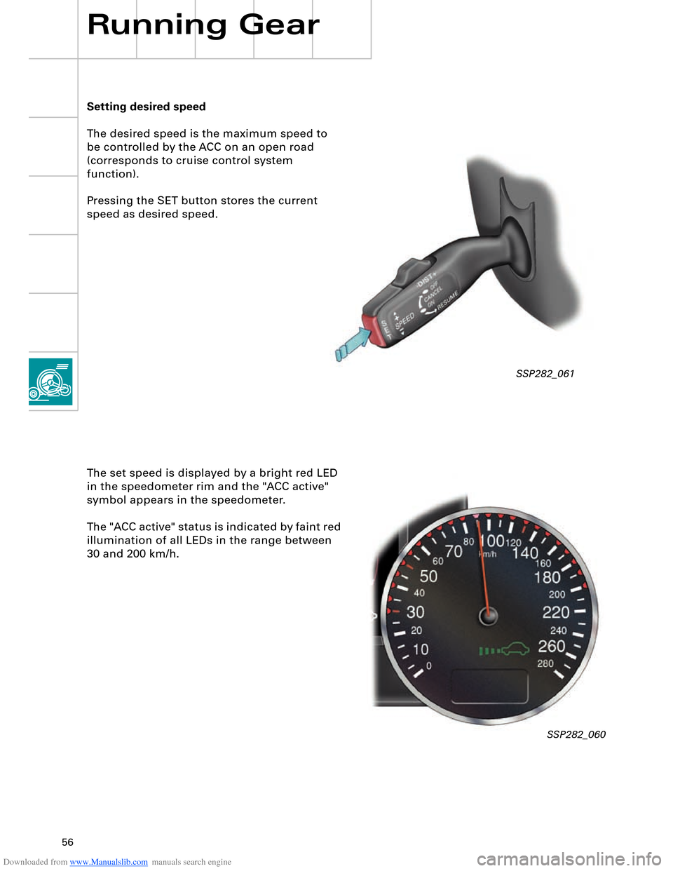
Setting desired speed
The desired speed is the maximum speed to
be controlled by the ACC on an open road
(corresponds to cruise control system
function).
Pressing the SET button stores the current
speed as desired speed.
Running Gear
The set speed is displayed by a bright red LED
in the speedometer rim and the "ACC active"
symbol appears in the speedometer.
The "ACC active" status is indicated by faint red
illumination of all LEDs in the range between
30 and 200 km/h.
SSP282_060
Page 57 of 96
Downloaded from www.Manualslib.com manuals search engine 57
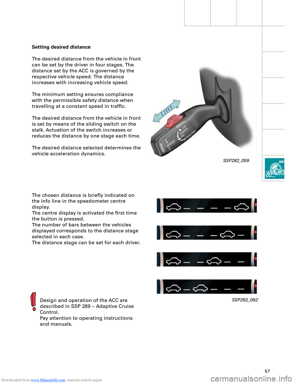
Setting desired distance
The desired distance from the vehicle in front
can be set by the driver in four stages. The
distance set by the ACC is governed by the
respective vehicle speed. The distance
increases with increasing vehicle speed.
The minimum setting ensures compliance
with the permissible safety distance when
travelling at a constant speed in traffic.
The desired distance from the vehicle in front
is set by means of the sliding switch on the
stalk. Actuation of the switch increases or
reduces the distance by one stage each time.
The desired distance selected determines the
vehicle acceleration dynamics.
The chosen distance is briefly indicated on
the info line in the speedometer centre
display.
The centre display is activated the first time
the button is pressed.
The number of bars between the vehicles
displayed corresponds to the distance stage
selected in each case.
The distance stage can be set for each driver.
Design and operation of the ACC are
described in SSP 289 – Adaptive Cruise
Control.
Pay attention to operating instructions
and manuals.SSP282_062
SSP282_059