Page 33 of 72
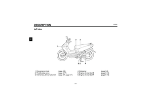
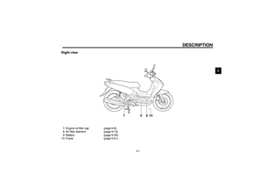
PERIODIC MAINTENANCE AND MINOR REPAIR
6-6
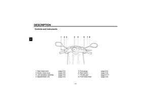
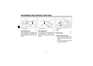
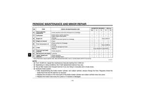
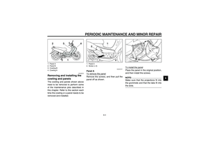
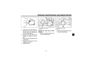
6 3. Remove the screws on cowling B.4. Pull cowling A off as shown.
NOTE:_ When removing cowling A, pull out on
the areas shown from bottom to top. _
To install the cowling1. Align the tabs in cowling A with the
slots of cowling B, and then push
cowling A into the original position.NOTE:_ When installing cowling A, push in on
the areas shown from top to bottom. _2. Install the screws on cowling B.
3. Install the screws on cowling A.
4. Install the license plate bracket by
installing the screws.
1. Screw (× 6)
2. Cowling BU5MXE0.book Page 6 Thursday, December 20, 2001 2:08 PM
Page 34 of 72

PERIODIC MAINTENANCE AND MINOR REPAIR
6-7
6
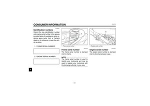
EAUT0004*
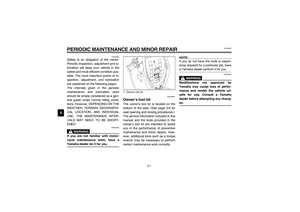
Checking the spark plug The spark plug is an important engine
component, which is easy to check.
Since heat and deposits will cause any
spark plug to slowly erode, the spark
plug should be removed and checked
in accordance with the periodic mainte-
nance and lubrication chart. In addition,
the condition of the spark plug can re-
veal the condition of the engine.
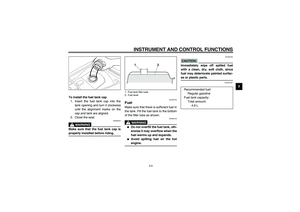
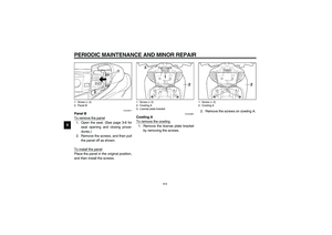
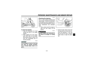
To remove the spark plug
1. Remove panel A. (See page 6-4
for panel removal and installation
procedures.)
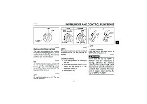
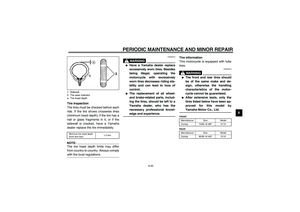
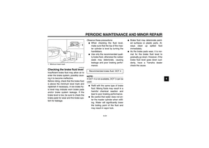
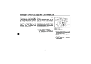
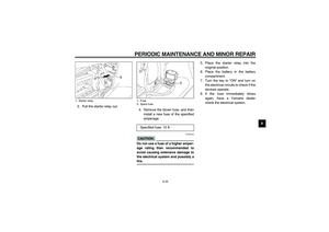
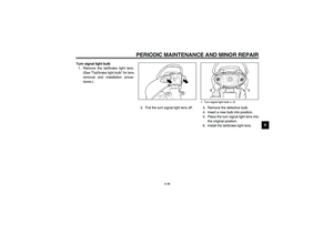
2. Remove the spark plug cap.3. Remove the spark plug as shown,
with the spark plug wrench includ-
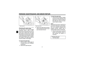
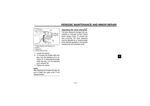
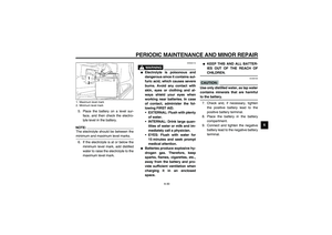
ed in the owner’s tool kit.To check the spark plug
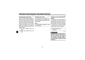
1. Check that the porcelain insulator
around the center electrode of the
spark plug is a medium-to-light tan
(the ideal color when the motor-
cycle is ridden normally).
NOTE:_ If the spark plug shows a distinctly dif-
ferent color, the engine could be defec-
tive. Do not attempt to diagnose such
problems yourself. Instead, have a
Yamaha dealer check the motorcycle. _2. Check the spark plug for electrode
erosion and excessive carbon or
other deposits, and replace it if
necessary.
1. Spark plug cap
1. Spark plug wrench
Specified spark plug:
CR7HSA (NGK)
U5MXE0.book Page 7 Thursday, December 20, 2001 2:08 PM
Page 35 of 72
PERIODIC MAINTENANCE AND MINOR REPAIR
6-8
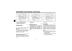
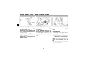
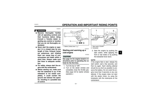
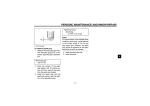
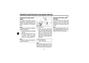
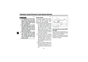
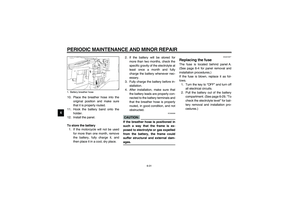
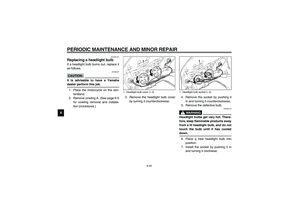
6 To install the spark plug
1. Measure the spark plug gap with a
wire thickness gauge and, if nec-
essary, adjust the gap to specifica-
tion.
2. Clean the surface of the spark
plug gasket and its mating sur-
face, and then wipe off any grime
from the spark plug threads.
3. Install the spark plug with the
spark plug wrench, and then tight-
en it to the specified torque.
NOTE:_ If a torque wrench is not available when
installing a spark plug, a good estimate
of the correct torque is 1/4–1/2 turn
past finger tight. However, the spark
plug should be tightened to the speci-
fied torque as soon as possible. _4. Install the spark plug cap.
5. Install the panel.
a. Spark plug gapSpark plug gap:
0.6–0.7 mm
Tightening torque:
Spark plug:
12.5 Nm (1.25 m·kgf)
U5MXE0.book Page 8 Thursday, December 20, 2001 2:08 PM
Page 36 of 72

PERIODIC MAINTENANCE AND MINOR REPAIR
6-9
6
EAUT0016*
Engine oil and oil strainer The engine oil level should be checked
before each ride. In addition, the oil
must be changed and the oil strainer
cleaned at the intervals specified in the
periodic maintenance and lubrication
chart.
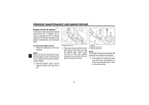
To check the engine oil level
1. Place the motorcycle on the cen-
terstand.NOTE:_ Make sure that the motorcycle is posi-
tioned straight up when checking the oil
level. A slight tilt to the side can result in
a false reading. _2. Start the engine, warm it up for
several minutes, and then turn it
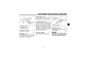
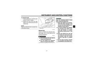
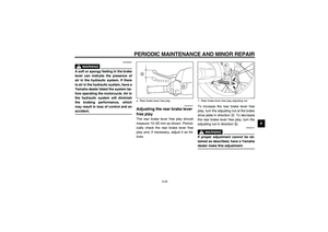
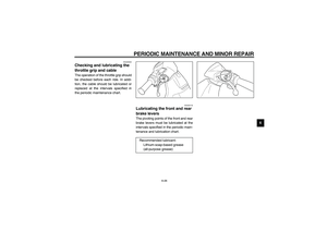
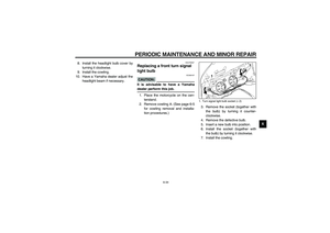
off.3. Wait a few minutes until the oil set-
tles, remove the oil filler cap, wipe
the dipstick clean, insert it back
into the oil filler hole (without
screwing it in), and then remove it
again to check the oil level.
NOTE:_ The engine oil should be between the
minimum and maximum level marks. _4. If the engine oil is below the mini-
mum level mark, add sufficient oil
of the recommended type to raise
it to the correct level.
1. Engine oil filler cap
1. Dipstick
2. Maximum level mark
3. Minimum level mark
U5MXE0.book Page 9 Thursday, December 20, 2001 2:08 PM
Page 37 of 72

PERIODIC MAINTENANCE AND MINOR REPAIR
6-10
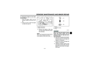
6 To change the engine oil and clean
the oil strainer
1. Start the engine, warm it up for
several minutes, and then turn it
off.
2. Place an oil pan under the engine
to collect the used oil.
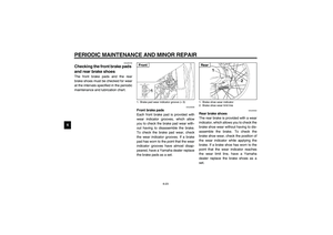
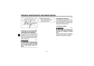
3. Remove the engine oil filler cap
and drain bolts to drain the oil from
the crankcase.
NOTE:_ When only changing the engine oil, re-
move engine oil drain bolt A only. _
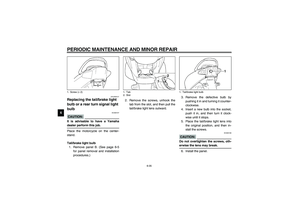
EC000070*
CAUTION:_ When removing the engine oil drain
bolt B, the O-ring, spring, and oil
strainer will fall out. Take care not to
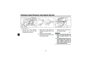
lose these parts. _4. Clean the oil strainer with solvent,
and then check it for damage and
replace it if necessary.
5. Check the O-ring for damage and
replace it if necessary.
6. Install the oil strainer, spring, O-ring
and engine oil drain bolts, and then
tighten the drain bolts to the speci-
fied torque.
1. Engine oil drain bolt A
2. Engine oil drain bolt B
1. Strainer
2. Compression spring
3. O-ring
U5MXE0.book Page 10 Thursday, December 20, 2001 2:08 PM
Page 38 of 72

PERIODIC MAINTENANCE AND MINOR REPAIR
6-11
6
NOTE:_ Make sure that the O-ring is properly
seated. _7. Add the specified amount of the
recommended engine oil, and
then install and tighten the engine
oil filler cap.
ECA00105
CAUTION:_ �
In order to prevent clutch slip-
page (since the engine oil also
lubricates the clutch), do not
mix any chemical additives with
the oil or use oils of grade “CD”
or higher. In addition, do not
use oils labeled “ENERGY CON-
SERVING II” or higher.
�
Make sure that no foreign mate-
rial enters the crankcase.
_8. Start the engine, and then let it idle
for several minutes while checking
it for oil leakage. If oil is leaking,
immediately turn the engine off
and check for the cause.
9. Turn the engine off, and then
check the oil level and correct it if
necessary.
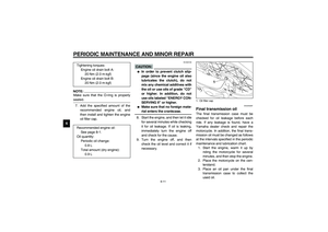
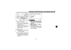
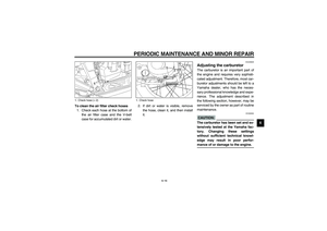
EAU04228*
Final transmission oil The final transmission case must be
checked for oil leakage before each
ride. If any leakage is found, have a
Yamaha dealer check and repair the
motorcycle. In addition, the final trans-
mission oil must be changed as follows
at the intervals specified in the periodic
maintenance and lubrication chart.
1. Start the engine, warm it up by
riding the motorcycle for several
minutes, and then stop the engine.
2. Place the motorcycle on the cen-
terstand.
3. Place an oil pan under the final
transmission case to collect the
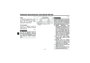
used oil. Tightening torques:
Engine oil drain bolt A:
20 Nm (2.0 m·kgf)
Engine oil drain bolt B:
20 Nm (2.0 m·kgf)
Recommended engine oil:
See page 8-1.
Oil quantity:
Periodic oil change:
0.8 L
Total amount (dry engine):
0.9 L1. Oil filler cap
U5MXE0.book Page 11 Thursday, December 20, 2001 2:08 PM
Page 39 of 72
PERIODIC MAINTENANCE AND MINOR REPAIR
6-12
6 4. Remove the oil filler cap and drain
bolt to drain the oil from the final
transmission case.
5. Install the final transmission oil
drain bolt, and then tighten it to the
specified torque.
6. Add the specified amount of the
recommended final transmission
oil, and then install and tighten the
oil filler cap.
EWA00062
WARNING
_ �
Make sure that no foreign mate-
rial enters the final transmis-
sion case.
�
Make sure that no oil gets on
the tire or wheel.
_7. Check the final transmission case
for oil leakage. If oil is leaking,
check for the cause.
1. Final transmission oil drain boltTightening torque:
Final transmission oil drain bolt:
22 Nm (2.2 m·kgf)
Recommended final transmission
oil:
See page 8-1.
Oil quantity:
0.1 L
U5MXE0.book Page 12 Thursday, December 20, 2001 2:08 PM
Page 40 of 72
PERIODIC MAINTENANCE AND MINOR REPAIR
6-13
6
EAUM0058*
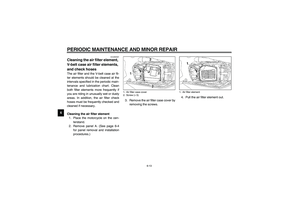
Cleaning the air filter element,
V-belt case air filter elements,
and check hoses The air filter and the V-belt case air fil-
ter elements should be cleaned at the
intervals specified in the periodic main-
tenance and lubrication chart. Clean
both filter elements more frequently if
you are riding in unusually wet or dusty
areas. In addition, the air filter check
hoses must be frequently checked and
cleaned if necessary.
Cleaning the air filter element
1. Place the motorcycle on the cen-
terstand.
2. Remove panel A. (See page 6-4
for panel removal and installation
procedures.)3. Remove the air filter case cover by
removing the screws.4. Pull the air filter element out.
1. Air filter case cover
2. Screw (× 5)
1. Air filter element
U5MXE0.book Page 13 Thursday, December 20, 2001 2:08 PM