Page 17 of 96

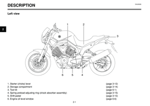
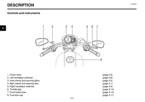
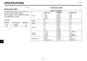
INSTRUMENT AND CONTROL FUNCTIONS
NOTE:
Depending on the market where the
motorcycle is sold, the speedometer can
be set to either mph or km/h. When the
speedometer is set to mph, the odometer
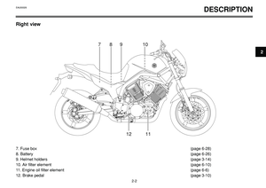
counts in miles (1 mile = 1.61 km).Odometer and tripmeter modes
Pushing the “SET” button switches the dis-
play between the odometer mode “ODO”
and the tripmeter modes “TRIP 1” and
“TRIP 2” in the following order: ODO 6
TRIP 1 6TRIP 2 6ODO
When the fuel warning light comes on, the
display will automatically change to the fu-
el reserve tripmeter mode “TRIP F” and
start counting the distance traveled from
that point. In that case, pushing the “SET”
button switches the display between the
various tripmeter and odometer modes in
the following order: TRIP F 6TRIP 1 6
TRIP 2 6ODO 6TRIP F
To reset a tripmeter, select it by pushing
the “SET” button, and then push the “RE-
SET” button for at least one second. If you
do not reset the fuel reserve tripmeter
manually, it will reset itself automatically
and the display will return to the prior
mode after refueling and traveling several
kilometers.Oil change indicator
At the initial 1,000 km (620 mi) and every
10,000 km (6,200 mi) thereafter, the mes-
sage “OIL CHANGE” appears in the dis-
play for a few seconds when the key is
turned to “ON”, to indicate that the engine
oil should be changed.
After changing the engine oil, reset the oil
change indicator.
If the engine oil is changed before the oil
change indicator appears in the display
(i.e. before the periodic oil change interval
has been reached), the indicator must be
reset after the oil change for the next peri-
odic oil change to be indicated at the cor-
rect time.
NOTE:
When the message “OIL CHANGE”
appears in the display, be sure to change
the engine oil as soon as possible. In addi-
tion to these kilometer-based oil changes,
be sure to have a Yamaha dealer perform
the annual checks specified in the period-
ic maintenance and lubrication chart on
page 6-2.
EAU00027
3-4
3
Page 18 of 96
INSTRUMENT AND CONTROL FUNCTIONS
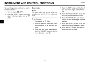
To reset the periodic maintenance and lu-
brication indicator:
1. Turn the key to “
B” (OFF).
2. Push the “RESET” button and hold it
down while turning the key to “
I”
(ON).Clock mode
NOTE:
The clock can only be set while the
speedometer unit is in the odometer
mode.
To set the clock:
1. Turn the key to “
I” (ON).
2. Push the “RESET” button and “SET”
button together for at least two sec-
onds.
3. When the hour digits start flashing,
push the “RESET” button to set the
hours (between 1 and 12).4. Push the “SET” button, and the first of
the two minute digits will start flash-
ing.
5. Push the “RESET” button to set the
first minute digit (between 0 and 5).
6. Push the “SET” button, and the sec-
ond of the two minute digits will start
flashing.
7. Push the “RESET” button to set the
second minute digit (between 0 and 9).
8. Push the “SET” button, and then re-
lease it to start the clock.
EAU00027
3-5
3
Page 19 of 96

INSTRUMENT AND CONTROL FUNCTIONS
NOTE:
The clock can only be set when the motor-
cycle is stopped. The clock does not auto-
matically adjust for Daylight Saving Time.
Therefore, when the time changes from
Standard Time to Daylight Saving Time
(and vice versa), the clock must be set
manually.
EAU00101
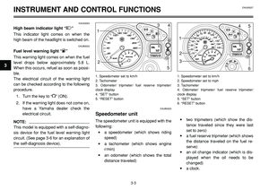
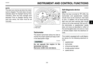
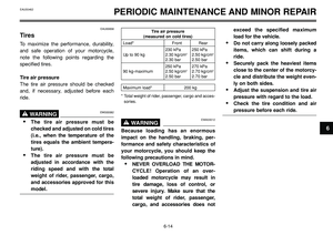
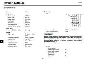
Tachometer
The electric tachometer allows the rider to
monitor the engine speed and keep it with-
in the ideal power range.
EC000003
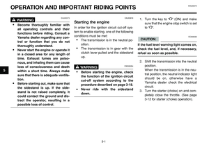
Do not operate the engine in the
tachometer red zone.
Red zone: 6,400 r/min and above.
CAUTION:
EAUB0004
Self-diagnosis device
NOTE:
When the key is turned to “
I” (ON), the
tachometer and speedometer needles
should move to the maximum, then back
to zero. In addition, the oil level warning
light and fuel level warning light should
come on for a few seconds, then go off. If
the tachometer or speedometer needle
does not move as described or either of
the warning lights does not come on, have
a Yamaha dealer check the electrical cir-
cuits.
This model is equipped with a self-diagno-
sis device for the following electrical cir-
cuits:
•speedometer
•tachometer
•oil level warning light
•throttle position sensor
•speed sensor.
3-6
31
2
1. Tachometer
2. Red zone
EAU00027
Page 20 of 96
INSTRUMENT AND CONTROL FUNCTIONSEAU00027
3-7
3
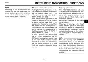
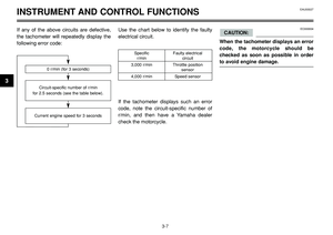
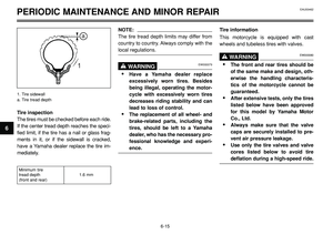
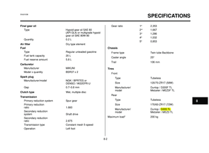
If any of the above circuits are defective,
the tachometer will repeatedly display the
following error code:Use the chart below to identify the faulty
electrical circuit.
If the tachometer displays such an error
code, note the circuit-specific number of
r/min, and then have a Yamaha dealer
check the motorcycle.EC000004
When the tachometer displays an error
code, the motorcycle should be
checked as soon as possible in order
to avoid engine damage.
CAUTION:
0 r/min (for 3 seconds)
Circuit-specific number of r/min
for 2.5 seconds (see the table below).
Specific Faulty electrical r/min circuit
3,000 r/min Throttle position
sensor
4,000 r/min Speed sensor
Current engine speed for 3 seconds
Page 21 of 96
EAU00119
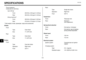
Pass switch “1”
Press this switch to flash the headlight.
EAU00121
Dimmer switch “2/1”
Set this switch to “
1” for the high beam
and to “
2” for the low beam.
EAU00129
Horn switch “o”
Press this switch to sound the horn.
INSTRUMENT AND CONTROL FUNCTIONS
3-8
3
3
1
2
4
EAU00109
Anti-theft alarm (optional)
This motorcycle can be equipped with an
optional anti-theft alarm by a Yamaha
dealer. Contact a Yamaha dealer for more
information.
EAU00118
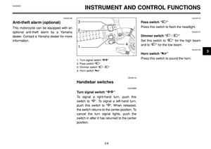
Handlebar switches
EAU03889
Turn signal switch “y
y”
To signal a right-hand turn, push this
switch to “
∆
∆”. To signal a left-hand turn,
push this switch to “
Ÿ
Ÿ”. When released,
the switch returns to the center position. To
cancel the turn signal lights, push the
switch in after it has returned to the center
position.
1. Turn signal switch “y
y”
2. Pass switch “1”
3. Dimmer switch “
2/ 1”
4. Horn switch “o”
EAU00027
Page 22 of 96

INSTRUMENT AND CONTROL FUNCTIONS
2
1
3
1
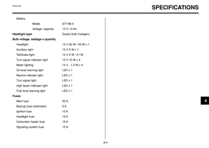
EAU03890
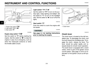
Engine stop switch “I/B”
Set this switch to “
I” before starting the
engine. Set this switch to “
B” to stop the
engine in case of an emergency, such as
when the motorcycle overturns or when
the throttle cable is stuck.
EAU03898
Light switch “G/E/H”
Set this switch to “
G” to turn on the aux-
iliary light, meter lighting and taillight. Set
the switch to “
E” to turn on the headlight
also. Set the switch to “
H” to turn off all the
lights.
EAU00143
Start switch “J”
Push this switch to crank the engine with
the starter.
EC000005
See page 5-1 for starting instructions
prior to starting the engine.
CAUTION:EAU00152
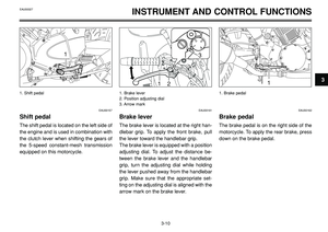
Clutch lever
The clutch lever is located at the left han-
dlebar grip. To disengage the clutch, pull
the lever toward the handlebar grip. To en-
gage the clutch, release the lever. The
lever should be pulled rapidly and re-
leased slowly for smooth clutch operation.
The clutch lever is equipped with a clutch
switch, which is part of the ignition circuit
cut-off system. (See page 3-18 for an ex-
planation of the ignition circuit cut-off sys-
tem).
3-9
3
1. Engine stop switch “I/B”
2. Light switch “G/E/H”
3. Start switch “J”1. Clutch lever
EAU00027
Page 23 of 96
INSTRUMENT AND CONTROL FUNCTIONS
1
1
2
1
23
4
3
1
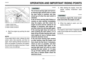
EAU00157
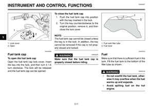
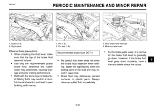
Shift pedal
The shift pedal is located on the left side of
the engine and is used in combination with
the clutch lever when shifting the gears of
the 5-speed constant-mesh transmission
equipped on this motorcycle.
EAU00161
Brake lever
The brake lever is located at the right han-
dlebar grip. To apply the front brake, pull
the lever toward the handlebar grip.
The brake lever is equipped with a position
adjusting dial. To adjust the distance be-
tween the brake lever and the handlebar
grip, turn the adjusting dial while holding
the lever pushed away from the handlebar
grip. Make sure that the appropriate set-
ting on the adjusting dial is aligned with the
arrow mark on the brake lever.
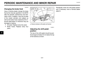
EAU00162
Brake pedal
The brake pedal is on the right side of the
motorcycle. To apply the rear brake, press
down on the brake pedal.
3-10
3
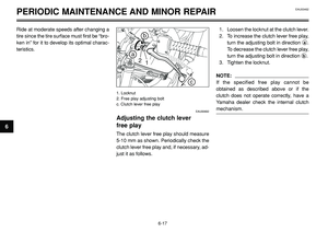
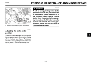
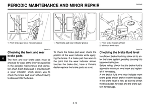
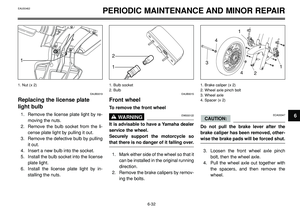
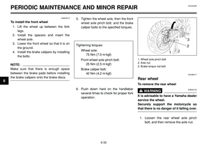
1. Shift pedal 1. Brake lever
2. Position adjusting dial
3. Arrow mark1. Brake pedal
EAU00027
Page 24 of 96

INSTRUMENT AND CONTROL FUNCTIONS
1
2
1
2
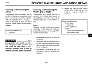
EAU02935
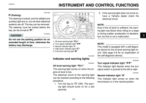
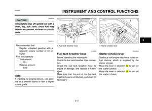
Fuel tank cap
To open the fuel tank cap
Open the fuel tank cap lock cover, insert
the key into the lock, and then turn it 1/4
turn clockwise. The lock will be released
and the fuel tank cap can be opened.To close the fuel tank cap
1. Push the fuel tank cap into position
with the key inserted in the lock.
2. Turn the key counterclockwise to the
original position, remove it, and then
close the lock cover.
NOTE:
The fuel tank cap cannot be closed unless
the key is in the lock. In addition, the key
cannot be removed if the cap is not prop-
erly closed and locked.
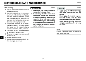
EWA00025WARNING0
Make sure that the fuel tank cap is
properly closed before riding.
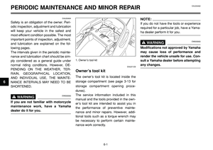
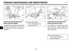
EAU03753
Fuel
Make sure that there is sufficient fuel in the
tank. Fill the fuel tank to the bottom of the
filler tube as shown.
EW000130WARNING0
•Do not overfill the fuel tank, other-
wise it may overflow when the fuel
warms up and expands.
•Avoid spilling fuel on the hot
engine.
3-11
3
1. Lock cover
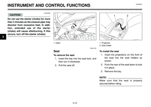
2. Open1. Fuel tank filler tube
2. Fuel level
EAU00027

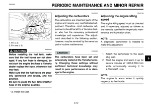
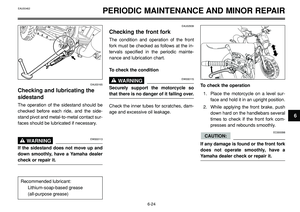
.
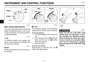
2. Push the “RESET” button and hold it
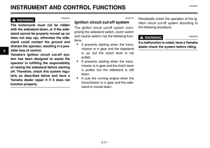
down while turning the key")


