B00540
A75980
Disconnect Wire
from Terminal B
Generator
Voltmeter BatteryAmmeter 19±6
± STARTING & CHARGINGCHARGING SYSTEM (1ZZ±FE/3ZZ±FE)
AVENSIS REPAIR MANUAL (RM1018E)
(b) Check that it fits properly in the ribbed grooves.
HINT:
Check with your hand to confirm that the belt has not slipped out
of the groove on the bottom of the pulley.
5. VISUALLY CHECK GENERATOR WIRING
(a) Check that the wiring is in good condition.
6. LISTEN FOR ABNORMAL NOISES FROM GENERATOR
(a) Check that there is no abnormal noise from the generator while the engine is running.
7. INSPECT CHARGE WARNING LIGHT CIRCUIT
(a) Turn the ignition switch ON. Check that the charge warning light comes on.
(b) Start the engine and check that the light goes off.
HINT:
If the light does not operate as specified, troubleshoot the charge warning light circuit.
8. INSPECT CHARGING CIRCUIT WITHOUT LOAD
(a) According to the following procedure, connect an amme-
ter and voltmeter as shown in the illustration.
(1) Disconnect the wire from terminal B of the generator
and connect it to the negative (±) lead of the amme-
ter.
(2) Connect the positive (+) lead of the ammeter to ter-
minal B of the generator
(3) Connect the positive (+) lead of the voltmeter to ter-
minal B of the generator.
(4) Ground the negative (±) lead of the voltmeter.
(b) Check the charging circuit.
(1) Keep the engine speed at 2,000 rpm, check the
reading on the ammeter and voltmeter.
Standard amperage: 10 A or less
Standard voltage: 12.9 to 14.9 V
HINT:
�If the voltmeter reading is more than standard voltage, re-
place the voltage regulator.
�If the voltmeter reading is less than the standard voltage,
check the voltage regulator and generator as follows:
9. INSPECT CHARGING CIRCUIT WITH LOAD
(a) Keep the engine speed at 2,000 rpm, turn on the high beam headlights and turn the heater blower
switch to the ºHIº position.
(b) Check the reading on the ammeter.
Standard amperage: 30 A or more
HINT:
�If the ammeter reading is less than standard amperage, repair the generator.
�If the battery is fully charged, the indication will sometimes be less than standard amperage.
190JE±02
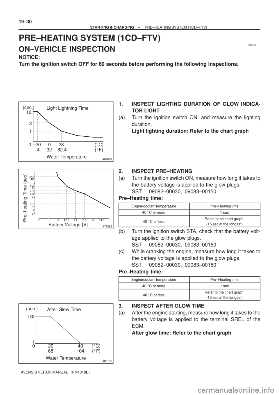
A82619
Light Lightning Time
Water Temperature ±20 0 28 0
±4 32 (�F) (�C)
82.4 (sec.)
10
3
1
A72562
Pre±heating Time (sec)Battery Voltage [V]
A80155
After Glow Time
Water Temperature68 104 (�F) 020 40(�C) (sec.)
1 19±30
± STARTING & CHARGINGPRE±HEATING SYSTEM (1CD±FTV)
AVENSIS REPAIR MANUAL (RM1018E)
PRE±HEATING SYSTEM (1CD±FTV)
ON±VEHICLE INSPECTION
NOTICE:
Turn the ignition switch OFF for 60 seconds before performing the following inspections.
1. INSPECT LIGHTING DURATION OF GLOW INDICA-
TOR LIGHT
(a) Turn the ignition switch ON, and measure the lighting
duration.
Light lighting duration: Refer to the chart graph
2. INSPECT PRE±HEATING
(a) Turn the ignition switch ON, measure how long it takes to
the battery voltage is applied to the glow plugs.
SST 09082±00030, 09083±00150
Pre±Heating time:
Engine coolant temperaturePre±Heating time
40 �C or more1 sec
40 �C or lessRefer to the chart graph
(15 sec at the longest)
(b) Turn the ignition switch STA, check that the battery volt-
age applied to the glow plugs.
SST 09082±00030, 09083±00150
(c) While cranking the engine, measure how long it takes to
the battery voltage is applied to the glow plugs.
SST 09082±00030, 09083±00150
Pre±Heating time:
Engine coolant temperaturePre±Heating time
40 �C or more1 sec
40 �C or lessRefer to the chart graph
(15 sec at the longest)
3. INSPECT AFTER GLOW TIME
(a) After the engine starting, measure how long it takes to the
battery voltage is applied to the terminal SREL of the
ECM.
After glow time: Refer to the chart graph

AVENSIS REPAIR MANUAL (RM1018E)
(b) Check that it fits")