Page 211 of 1690

12±17
AVENSIS REPAIR MANUAL (RM1018E)
EGR SYSTEM (1CD±FTV)
ON±VEHICLE INSPECTION
HINT:
In a malfunction where the EGR system is always on, black")
1209I±02
± EMISSION CONTROLEGR SYSTEM (1CD±FTV)
12±17
AVENSIS REPAIR MANUAL (RM1018E)
EGR SYSTEM (1CD±FTV)
ON±VEHICLE INSPECTION
HINT:
In a malfunction where the EGR system is always on, black smoke or white smoke may be emitted from the
exhaust pipe. If this occurs, inspect the EGR system as well.
1. INSPECT SEATING OF EGR VALVE
(a) Start the engine and check that it starts and runs at idle.
2. INSPECT HOT ENGINE CONDITION (WHEN USING HAND±HELD TESTER)
(a) Connect the hand±held tester to the DLC3.
(b) Start the engine and run it at idle.
(c) Select the ACTIVE TEST mode on the hand±held tester.
HINT:
Refer to the hand±held tester operator's manual for further details.
(d) Warm up the engine, the coolant temperature should be above 75�C (109�F) and bellow 90�C
(194�F).
(e) Check that the AFM reading is 5�ega�8 g/s with the engine idling.
(f) Operate the EGR valve with a hand±held tester. Regulate the valve opening angle to 0, and check that
the AFM reading is 11�ega�17 g/s..
If the AFM reading is out of range in either (e) or (f), replace the EGR valve.
If the AFM is out of range in both (e) and (f), replace the air flow meter (air cleaner) and check the EGR valve
operation again.
3. INSPECT HOT ENGINE CONDITION (WHEN NOT USING HAND±HELD TESTER)
(a) Install the vacuum gauge.
(1) Using a 3±way connector, connect a vacuum gauge to the hose between the intake manifold and
the turbo pressure sensor.
(b) Warm up the engine, the coolant temperature should be above 75�C (109�F) and bellow 90�C
(194�F).
(c) Check that the vacuum gauge indicates about more than 2.5 kPa (19 mmHg 0.7 in Hg).
(d) Stop the engine (IG OFF), remove the EGR valve connector, restart the engine, and check that load
under idling is less than 2.5 kPa (19 mmHg 0.7 in Hg).
If the load pressure exceeds the above value, replace the EGR valve.
Page 213 of 1690

12±9
AVENSIS REPAI")
A77115
Ohmmeter
Resistance
A77116
Ohmmeter
No continuity
A77117
Air E F
A77118
Air E
F
Battery
A61829
+B HT
E1 Bank 1 Sensor 1:
± EMISSION CONTROLEMISSION CONTROL SYSTEM (1AZ±FE)
12±9
AVENSIS REPAIR MANUAL (RM1018E)
4. INSPECT VACUUM SWITCHING VALVE ASSY NO.1
(a) Inspect VSV for open circuit.
(1) Using an ohmmeter, measure resistance between
the terminals.
Resistance: 26 to 30 � at 20�C (68�F)
If the resistance is not as specified, replace the VSV.
(b) Inspect the VSV for ground.
(1) Using an ohmmeter, check that there is no continu-
ity between each terminal and the body.
If there is continuity, replace the VSV.
(c) Inspect the VSV operation.
(1) Check that air flows with a little difficulty from port E
to port F.
(2) Apply battery voltage across the terminals.
(3) Check that air flows from port E to port F.
If operation is not as specified, replace the VSV.
5. INSPECT AIR FUEL RATIO SENSOR
(a) Bank 1 Sensor 1:
(1) Using an ohmmeter, measure the resistance be-
tween the terminals.
Resistance:
Terminal No.Resistance
1 (HT) ± 2 (+B)1.8 to 3.4 � at 20 �C (68 �F)
1 (HT) ± (+B)5.0 to 7.5 � at 500 �C (932 �F)
1 (HT) ± 4 (E1)No Continuity
If the resistance is not as specified, replace the sensor.
Page 214 of 1690
A60559
+B HT
Bank 2 Sensor 1:
E1
A62378
+B
HT
E1
� �
� �
12±10
± EMISSION CONTROLEMISSION CONTROL SYSTEM (1AZ±FE)
AVENSIS REPAIR MANUAL (RM1018E)
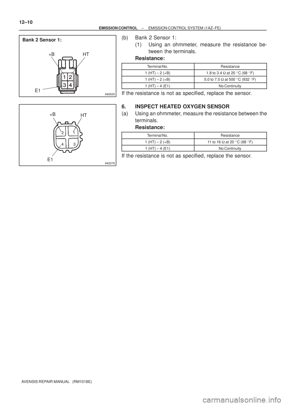
(b) Bank 2 Sensor 1:
(1) Using an ohmmeter, measure the resistance be-
tween the terminals.
Resistance:
Terminal No.Resistance
1 (HT) ± 2 (+B)1.8 to 3.4 � at 20 �C (68 �F)
1 (HT) ± 2 (+B)5.0 to 7.5 � at 500 �C (932 �F)
1 (HT) ± 4 (E1)No Continuity
If the resistance is not as specified, replace the sensor.
6. INSPECT HEATED OXYGEN SENSOR
(a) Using an ohmmeter, measure the resistance between the
terminals.
Resistance:
Terminal No.Resistance
1 (HT) ± 2 (+B)11 to 16 � at 20 �C (68 �F)
1 (HT) ± 4 (E1)No Continuity
If the resistance is not as specified, replace the sensor.
Page 215 of 1690

AVENSIS REPAIR MANUAL (RM1018E)
EMISSION CONTROL SYSTEM (1AZ±FE)
ON±VEHICLE INSPECTION
1. INSPECT")
1209E±02
A65749
E1
OX2BOX1B
ECM
A77114
12±6
± EMISSION CONTROLEMISSION CONTROL SYSTEM (1AZ±FE)
AVENSIS REPAIR MANUAL (RM1018E)
EMISSION CONTROL SYSTEM (1AZ±FE)
ON±VEHICLE INSPECTION
1. INSPECT AIR±FUEL RATIO COMPENSATION SYS-
TEM
HINT:
You can also check the system by choosing ºDATA MONITOR/
O
2 SENSOR OUTPUT VOLTAGEº on the monitor of the hand±
held tester.
(a) Connect the hand±held tester to terminals 21 (OX1B) and
7 (E1) and to terminals 29 (OX2B) and 7 (E1) of the ECM.
CAUTION:
Connect test leads from the back side of the connector with
the ECM connected.
(b) Warm up the heated oxygen sensor with the engine
speed at 2,500 rpm for approximately 2 minutes.
(c) Confirm that the voltage output varies between 0V to 1V
with the engine speed at 2,500 rpm.
OK:
The voltage output varies more than 8 times in 10 se-
conds.
CAUTION:
�Perform the check immediately after the warming up.
�If the voltage variation could not be verified, warm up
the heated oxygen sensor again.
2. INSPECT FUEL CUT OFF RPM
(a) Increase the engine speed to at least 3,500 rpm.
(b) Use a sound scope to check for injector operating sounds.
(c) Check that injector operating sounds stops momentarily and then resumes when the throttle lever is
released.
3. INSPECT EVAPORATIVE EMISSION CONTROL SYS-
TEM
(a) After starting the engine, disconnect the vacuum hose
shown in the illustration.
(b) Check if vacuum occurs at the VSV port when choosing
ºACTIVE TESTº and ºPURGE VSVº according to the dis-
play on hand±held tester.
(c) Finish ºACTIVE TESTº, then reconnect the vacuum hose.
(d) After entering to ºECU DATA MONITORº on the hand±
held tester, choose ºPURGE VSVº to check the operation
of the purge VSV.
(e) After driving the vehicle with a warm engine, confirm that
the VSV turns from off to on.
Page 218 of 1690

AVENSIS REP")
A77115
Ohmmeter
Resistance
A77116
Ohmmeter
No continuity
A77117
Air E F
A77118
Air E
F
Battery
A64543
+B
Bank 2 Sensor 1:
HT
E1
12±14
± EMISSION CONTROLEMISSION CONTROL SYSTEM (1AZ±FSE)
AVENSIS REPAIR MANUAL (RM1018E)
4. INSPECT VACUUM SWITCHING VALVE ASSY NO.1
(a) Inspect VSV for open circuit.
(1) Using an ohmmeter, measure resistance between
the terminals.
Resistance: 26 to 30 � at 20�C (68�F)
If the resistance is not as specified, replace the VSV.
(b) Inspect the VSV for ground.
(1) Using an ohmmeter, check that there is no continu-
ity between each terminal and the body.
If there is continuity, replace the VSV.
(c) Inspect the VSV operation.
(1) Check that air flows with a little difficulty from port E
to port F.
(2) Apply battery voltage across the terminals.
(3) Check that air flows from port E to port F.
If operation is not as specified, replace the VSV.
5. INSPECT HEATED OXYGEN SENSOR
(a) Bank 2 Sensor 1:
(1) Using an ohmmeter, measure the resistance be-
tween the terminals.
Resistance:
Terminal No.Resistance
1 (HT) ± 2 (+B)11 to 16 � at 20 �C (68 �F)
1 (HT) ± 4 (E1)No Continuity
If the resistance is not as specified, replace the sensor.
Page 219 of 1690
A62378
+B
HT
E1
� �
� �
Bank 2 Sensor 2:
A62378
+B
HT
E1
� �
� �
Bank 1 Sensor 1, 2:
± EMISSION CONTROLEMISSION CONTROL SYSTEM (1AZ±FSE)
12±15
AVENSIS REPAIR MANUAL (RM1018E)
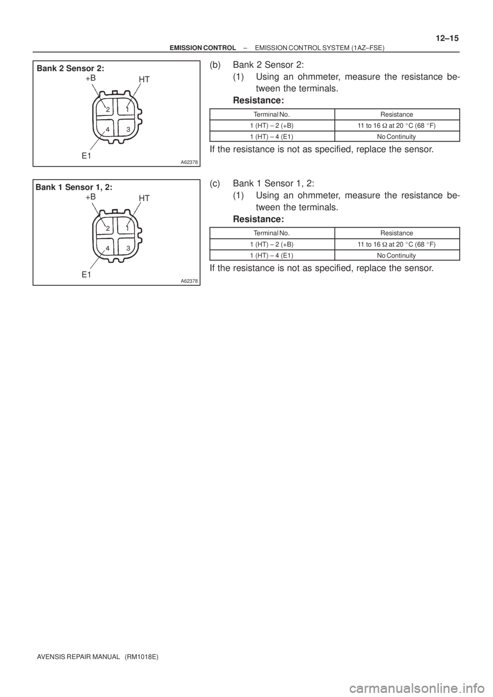
(b) Bank 2 Sensor 2:
(1) Using an ohmmeter, measure the resistance be-
tween the terminals.
Resistance:
Terminal No.Resistance
1 (HT) ± 2 (+B)11 to 16 � at 20 �C (68 �F)
1 (HT) ± 4 (E1)No Continuity
If the resistance is not as specified, replace the sensor.
(c) Bank 1 Sensor 1, 2:
(1) Using an ohmmeter, measure the resistance be-
tween the terminals.
Resistance:
Terminal No.Resistance
1 (HT) ± 2 (+B)11 to 16 � at 20 �C (68 �F)
1 (HT) ± 4 (E1)No Continuity
If the resistance is not as specified, replace the sensor.
Page 220 of 1690

12±11
AVENSIS REPAIR MANUAL (RM1018E)
EMISSION CONTROL SYSTEM (1AZ±FSE)
ON±VEHICLE INSPECTI")
1209G±02
A59588
E1
OX1AOX1B
OX2B OX2A
ECM
A77114
± EMISSION CONTROLEMISSION CONTROL SYSTEM (1AZ±FSE)
12±11
AVENSIS REPAIR MANUAL (RM1018E)
EMISSION CONTROL SYSTEM (1AZ±FSE)
ON±VEHICLE INSPECTION
1. INSPECT AIR±FUEL RATIO COMPENSATION SYS-
TEM
HINT:
You can also check the system by choosing ºDATA MONITOR/
O
2 SENSOR OUTPUT VOLTAGEº on the monitor of the hand±
held tester.
(a) Connect the hand±held tester to the following each pair
of the ECM terminals:
(1) Terminals 21 (OX1B) and 1 (E1)
(2) Terminals 22 (OX1A) and 1 (E1)
(3) Terminals 23 (OX2A) and 1 (E1)
(4) Terminals 29 (OX2B) and 1 (E1)
CAUTION:
Connect test leads from the back side of the connector with
the ECU connected.
(b) Warm up the heated oxygen sensor with the engine
speed at 2,500 rpm for approximately 2 minutes.
(c) Confirm that the voltage output varies between 0V to 1V
with the engine speed at 2,500 rpm.
OK:
The voltage output varies more than 8 times in 10 se-
conds.
CAUTION:
�Perform the check immediately after the warming up.
�If the voltage variation could not be verified, warm up
the heated oxygen sensor again.
2. INSPECT FUEL CUT OFF RPM
(a) Increase the engine speed to at least 3,500 rpm.
(b) Use a sound scope to check for injector operating sounds.
(c) Check that the injector operating sounds stops momentarily and then resumes that when the throttle
lever is released.
3. INSPECT EVAPORATIVE EMISSION CONTROL SYS-
TEM
(a) After starting the engine, disconnect the vacuum hose
shown in the illustration.
(b) Check if vacuum occurs at the VSV port when choosing
ºACTIVE TESTº and ºPURGE VSVº according to the dis-
play on hand±held tester.
(c) Finish ºACTIVE TESTº, then reconnect the vacuum hose.
(d) After entering to ºECU DATA MONITORº on the hand±
held tester, choose ºPURGE VSVº to check the operation
of the purge VSV.
(e) After driving the vehicle with a warm engine, confirm that
the VSV turns from off on to.
Page 224 of 1690

A77118
Air E
F
Battery
A60562
Cylinder Head Side
A60563
Intake Manifold Side
A64543
+B
Bank 1 Sensor 1:
HT1A
E1
A77126
HT +B
Bank 1 Sensor 2:
E1 12±4
± EMISSION CONTROLEMISSION CONTROL SYSTEM (1ZZ±FE/3ZZ±FE)
AVENSIS REPAIR MANUAL (RM1018E)
(2) Apply battery voltage across the terminals.
(3) Check that air flows from port E to port F.
If operation is not as specified, replace the VSV.
3. INSPECT VENTILATION VALVE SUB±ASSY
(a) Blow air into the cylinder head side, and check that air
passes through easily.
CAUTION:
Do not suck air through the valve. If contains petroleum
substances and is harmful.
(b) Blow air into the intake manifold side, and check that air
passes through with difficulty.
HINT:
If operation is not as specified, replace the PCV valve.
4. IINSPECT HEATED OXYGEN SENSOR
(a) Bank 1 Sensor 1:
(1) Using an ohmmeter, measure the resistance be-
tween the terminals.
Resistance:
Terminal No.Resistance
1 (HT1A) ± 2 (+B)5 to 10 � at 20 �C (68 �F)
1 (HT1A) ± 4 (E1)No Continuity
If the resistance is not as specified, replace the sensor.
(b) Bank 1 Sensor 2:
(1) Using an ohmmeter, measure the resistance be-
tween the terminals.
Resistance:
Terminal No.Resistance
1 (HT) ± 2 (+B)11 to 16 � at 20 �C (68 �F)
1 (HT) ± 4 (E1)No Continuity
If the resistance is not as specified, replace the sensor.