Page 88 of 1690

11. INSTALL STEERING SENSOR
(a) Install the steering sensor adapter to the column shaft.
HINT:
At that tim")
F42641
F42642
F45427
F45426
32±66
±
BRAKE STEERING SENSOR
AVENSIS REPAIR MANUAL (RM1018E)
11. INSTALL STEERING SENSOR
(a) Install the steering sensor adapter to the column shaft.
HINT:
At that time, the projection of the steering sensor adapter
should be fit in the hole on the steering column shaft.
(b) Install the steering sensor to the column shaft.
HINT:
�At that time, the pick of the steering sensor should be fit
to the pick of the steering sensor adapter.
�After installation, make sure the steering sensor is fixed
securely in the steering sensor adapter.
(c) Place the steering column assy on the V±blocks and rub- ber stick.
(d) Install the 2 new tilt steering support collar No.1 to the steering column assy.
(e) Using a extension bar and hammer, install the steering column bracket spacer to the steering column assy.
NOTICE:
�During this procedure, do not apply the strong shock
to the steering sensor.
�Do not apply any grease or oil on the pin.
12.INSTALL STEERING INTERMEDIATE SHAFT ASSY NO.2 (See page 50±9)
13.INSTALL STEERING COLUMN ASSY (See page 50±9)
14.INSTALL SPIRAL CABLE SUB±ASSY (See page 60±26)
15. INSTALL STEERING COLUMN COVER W/INSTRUMENT CLUSTER FINISH PANEL ASSY (See page 50±9)
16.INSTALL STEERING COLUMN COVER LWR (See page 50±9)
17.INSTALL STEERING WHEEL ASSY (See page 50±9)
18. INSPECT STEERING WHEEL CENTER POINT
19.INSTALL HORN BUTTON ASSY (See page 60±17)
Page 89 of 1690
±
BRAKE STEERING SENSOR
32±67
AVENSIS REPAIR MANUAL (RM1018E)
20.CONNECT BATTERY NEGATIVE TERMINAL (See page 60±1)
21.INSPECT SRS WARNING LIGHT (See page 05±1184)
22.INSPECT ABS WARNING LIGHT AND VSC WARNING LIGHT (See page 05±756)
Page 97 of 1690

YAWRATE SENSOR
REPLACEMENT
NOTICE:
�Dont use the dropped or damaged yawrate sensor.
�Free from t")
320GM±02
G23169
G23170
G23171
G23170
±
BRAKE YAWRATE SENSOR
32±63
AVENSIS REPAIR MANUAL (RM1018E)
YAWRATE SENSOR
REPLACEMENT
NOTICE:
�Don't use the dropped or damaged yawrate sensor.
�Free from the foreing matters between yawrate sensor braket and body.
�Make sure the sensor direction.
1.REMOVE FRONT SEAT ASSEMBLY LH (See page 72±11 or 72±16)
2. REMOVE YAWRATE SENSOR BRACKET
(a) Remove the bolt and upper part of the yawrate sensorbracket.
3. REMOVE YAWRATE SENSOR
(a) Disconnect the yawrate sensor connector from the yaw- rate sensor.
(b) Remove the 2 bolts and the yawrate sensor with the yaw- rate sensor bracket from the body.
(c) Remove the 2 nuts and yawrate sensor from the yawrate sensor bracket.
4. INSTALL YAWRATE SENSOR
(a) Install the 2 nuts and yawrate sensor to the yawrate sen- sor bracket.
Torque: 6 N �m (61 ft �lbf, 53 in. �lbf)
(b) Install the 2 bolts and the yawrate sensor with the yawrate sensor bracket to the body.
Torque: 21 N �m (214 ft �lbf, 15 ft �lbf)
(c) Connect the yawrate sensor connector to the yawrate sensor.
Page 98 of 1690
G23169
32±64
±
BRAKE YAWRATE SENSOR
AVENSIS REPAIR MANUAL (RM1018E)
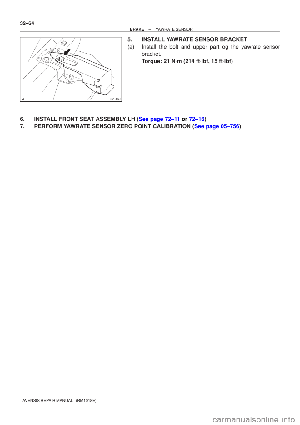
5. INSTALL YAWRATE SENSOR BRACKET
(a) Install the bolt and upper part og the yawrate sensor bracket.
Torque: 21 N �m (214 ft �lbf, 15 ft �lbf)
6.INSTALL FRONT SEAT ASSEMBLY LH (See page 72±11 or 72±16)
7.PERFORM YAWRATE SENSOR ZERO POINT CALIBRATION (See page 05±756)
Page 99 of 1690

YAWRATE SENSOR
REPLACEMENT
NOTICE:
�Dont use the dropped or damaged yawrate sensor.
�Free from t")
320GM±02
G23169
G23170
G23171
G23170
±
BRAKE YAWRATE SENSOR
32±63
AVENSIS REPAIR MANUAL (RM1018E)
YAWRATE SENSOR
REPLACEMENT
NOTICE:
�Don't use the dropped or damaged yawrate sensor.
�Free from the foreing matters between yawrate sensor braket and body.
�Make sure the sensor direction.
1.REMOVE FRONT SEAT ASSEMBLY LH (See page 72±11 or 72±16)
2. REMOVE YAWRATE SENSOR BRACKET
(a) Remove the bolt and upper part of the yawrate sensorbracket.
3. REMOVE YAWRATE SENSOR
(a) Disconnect the yawrate sensor connector from the yaw- rate sensor.
(b) Remove the 2 bolts and the yawrate sensor with the yaw- rate sensor bracket from the body.
(c) Remove the 2 nuts and yawrate sensor from the yawrate sensor bracket.
4. INSTALL YAWRATE SENSOR
(a) Install the 2 nuts and yawrate sensor to the yawrate sen- sor bracket.
Torque: 6 N �m (61 ft �lbf, 53 in. �lbf)
(b) Install the 2 bolts and the yawrate sensor with the yawrate sensor bracket to the body.
Torque: 21 N �m (214 ft �lbf, 15 ft �lbf)
(c) Connect the yawrate sensor connector to the yawrate sensor.
Page 100 of 1690
G23169
32±64
±
BRAKE YAWRATE SENSOR
AVENSIS REPAIR MANUAL (RM1018E)
5. INSTALL YAWRATE SENSOR BRACKET
(a) Install the bolt and upper part og the yawrate sensor bracket.
Torque: 21 N �m (214 ft �lbf, 15 ft �lbf)
6.INSTALL FRONT SEAT ASSEMBLY LH (See page 72±11 or 72±16)
7.PERFORM YAWRATE SENSOR ZERO POINT CALIBRATION (See page 05±756)
Page 135 of 1690

16±17
AVENSIS REPAIR MANUAL (RM1018E)
COOLING FAN SYSTEM (1AZ±FE)
ON±VEHICLE INSPECTION
HINT:
It is normal that the cooling fan sometime rotates w")
1600R±13
± COOLINGCOOLING FAN SYSTEM (1AZ±FE)
16±17
AVENSIS REPAIR MANUAL (RM1018E)
COOLING FAN SYSTEM (1AZ±FE)
ON±VEHICLE INSPECTION
HINT:
It is normal that the cooling fan sometime rotates when the ignition switch is turned from ACC to ON.
1. CHECK COOLING FAN OPERATION WITH LOW TEMPERATURE (Below 77�C (171�F))
(a) Turn the ignition switch ON.
(b) Check that the cooling fan stops.
If not, check the cooling fan relay and engine coolant temperature sensor, and check for disconnection of
connectors or wire break between the cooling fan relay and engine coolant temperature sensor.
(c) Disconnect the engine coolant temperature sensor connector.
(d) Check that the cooling fan rotates.
If not, check the fuses, cooling fan relay, ECM and cooling fan, and check for a short circuit between the
cooling fan relay and engine coolant temperature sensor.
(e) Reconnect the engine coolant temperature sensor connector.
2. CHECK COOLING FAN OPERATION WITH HIGH TEMPERATURE (Above 95.5�C (204�F))
(a) Start the engine, and raise coolant temperature to above 95.5�C (204�F).
HINT:
Coolant temperature is the detected value by the engine coolant temperature sensor on the water outlet.
(b) Check that the cooling fan rotates.
If not, replace the engine coolant temperature sensor.
3. INSPECT COOLING FAN
(a) Disconnect the cooling fan connector.
(b) Connect battery and ammeter to the cooling fan connector.
(c) Check that the cooling fan rotates smoothly, and check the reading on the ammeter.
Standard amperage:
5.2 to 8.2 A at 20�C (68�F) (M/T)
8.3 to 11.3 A at 20�C (68�F) (A/T)
(d) Reconnect the cooling fan connector.
4. INSPECT COOLING FAN No.2 (With Air Conditioner)
(a) Disconnect the cooling fan connector.
(b) Connect battery and ammeter to the cooling fan connector.
(c) Check that the cooling fan rotates smoothly, and check the reading on the ammeter.
Standard amperage:
5.2 to 8.2 A at 20�C (68�F) (M/T)
8.3 to 11.3 A at 20�C (68�F) (A/T)
(d) Reconnect the cooling fan connector.
Page 137 of 1690

16±29
AVENSIS REPAIR MANUAL (RM1018E)
COOLING FAN SYSTEM (1AZ±FSE)
ON±VEHICLE INSPECTION
HINT:
It is normal that the cooling fan sometime rotates")
1600R±12
± COOLINGCOOLING FAN SYSTEM (1AZ±FSE)
16±29
AVENSIS REPAIR MANUAL (RM1018E)
COOLING FAN SYSTEM (1AZ±FSE)
ON±VEHICLE INSPECTION
HINT:
It is normal that the cooling fan sometime rotates when the ignition switch is turned from ACC to ON.
1. CHECK COOLING FAN OPERATION WITH LOW TEMPERATURE (Below 83�C (181�F))
(a) Turn the ignition switch ON.
(b) Check that the cooling fan stops.
If not, check the cooling fan relay and engine coolant temperature sensor, and check for disconnection of
connectors or wire break between the cooling fan relay and engine coolant temperature sensor.
(c) Disconnect the engine coolant temperature sensor connector.
(d) Check that the cooling fan rotates.
If not, check the fuses, cooling fan relay, ECM and cooling fan, and check for a short circuit between the
cooling fan relay and engine coolant temperature sensor.
(e) Reconnect the engine coolant temperature sensor connector.
2. CHECK COOLING FAN OPERATION WITH HIGH TEMPERATURE (Above 100�C (212�F))
(a) Start the engine, and raise coolant temperature to above 100�C (212�F).
HINT:
Coolant temperature is the detected value by the engine coolant temperature sensor on the water outlet.
(b) Check that the cooling fan rotates.
If not, replace the engine coolant temperature sensor.
3. INSPECT COOLING FAN
(a) Disconnect the cooling fan connector.
(b) Connect battery and ammeter to the cooling fan connector.
(c) Check that the cooling fan rotates smoothly, and check the reading on the ammeter.
Standard amperage:
5.2 to 8.2 A at 20�C (68�F) (M/T)
8.3 to 11.3 A at 20�C (68�F) (A/T)
(d) Reconnect the cooling fan connector.
4. INSPECT COOLING FAN No.2 (With Air Conditioner)
(a) Disconnect the cooling fan connector.
(b) Connect battery and ammeter to the cooling fan connector.
(c) Check that the cooling fan rotates smoothly, and check the reading on the ammeter.
Standard amperage:
5.2 to 8.2 A at 20�C (68�F) (M/T)
8.3 to 11.3 A at 20�C (68�F) (A/T)
(d) Reconnect the cooling fan connector.

20.CONNECT BATTERY NEGATIVE TERMINAL (See page 60±1)
21.INSPECT SRS WARNING LIGHT (See page 05±1184)
22.INSPECT ABS WARNING LIGHT AN")