Page 142 of 1690

16±5
AVENSIS REPAIR MANUAL (RM1018E)
COOLING FAN SYSTEM (1ZZ±FE/3ZZ±FE)
ON±VEHICLE INSPECTION
HINT:
It is normal that the cooling fan som")
1600R±14
± COOLINGCOOLING FAN SYSTEM (1ZZ±FE/3ZZ±FE)
16±5
AVENSIS REPAIR MANUAL (RM1018E)
COOLING FAN SYSTEM (1ZZ±FE/3ZZ±FE)
ON±VEHICLE INSPECTION
HINT:
It is normal that the cooling fan sometime rotates when the ignition switch is turned from ACC to ON.
1. CHECK COOLING FAN OPERATION WITH LOW TEMPERATURE (Below 94.5�C (202�F))
(a) Turn the ignition switch ON.
(b) Check that the cooling fan stops.
If not, check the cooling fan relay and engine coolant temperature sensor, and check if there is its connector
disconnection or circuit open between them.
(c) Disconnect the engine coolant temperature sensor connector.
(d) Check that the cooling fan rotates.
If not, check the fuses, cooling fan relay, ECM and cooling fan, and check for short in a circuit between the
cooling fan relay and the engine coolant temperature sensor.
(e) Reconnect the engine coolant temperature sensor connector.
2. CHECK COOLING FAN OPERATION WITH HIGH TEMPERATURE (Above 96�C (205�F))
(a) Start the engine, and raise coolant temperature to above 96�C (205�F).
HINT:
Coolant temperature is detected by the engine coolant temperature sensor on the water outlet.
(b) Check that the cooling fan rotates.
If not, replace the engine coolant temperature sensor.
3. INSPECT COOLING FAN
(a) Disconnect the cooling fan connector.
(b) Connect battery and ammeter to the connector.
(c) Check that the cooling fan rotates smoothly, and check the reading on the ammeter.
Standard amperage: Approximately. 8 to 12 A at 20�C (68�F)
(d) Reconnect the cooling fan connector.
Page 179 of 1690
160MW±01
B12054
SST
B12052
B12053
Pry
PryPry
±
COOLING WATER PUMP ASSY(1AZ±FE)
16±21
AVENSIS REPAIR MANUAL (RM1018E)
WATER PUMP ASSY(1AZ±FE)
REPLACEMENT
1.DRAIN COOLANT (See page 16±19)
2. REMOVE RADIATOR SUPPORT OPENING COVER
3. REMOVE ENGINE ROOM COVER SIDE
4. REMOVE ENGINE UNDER COVER RH
5.REMOVE FAN AND GENERATOR V BELT (See page 14±105)
SST 09249±63010
6.REMOVE GENERATOR ASSY (See page 19±20)
7. REMOVE WATER PUMP PULLEY
(a) Using SST, remove 4 bolts and pump pulley.SST 09960±10010 (09962±01000, 09963±00700)
(b) Disconnect the crankshaft position sensor wire clamp from the water pump.
(c) Disconnect the crankshaft position sensor wire from the clamp on the water pump.
8. REMOVE WATER PUMP ASSY
(a) Remove 4 bolts, 2 nuts, wire clamp and water pump.
(b) Using a screwdriver, pry between the water pump and cyl- inder block, and remove the water pump.
NOTICE:
Be careful not to damage the contact surface of the water
pump and cylinder block.
Page 180 of 1690

AVENSIS REPAIR MANUAL (RM1018E)
9.INSTALL WATER PUMP ASSY
(a)Remove any old packing (FIPG)")
A57664
Seal Width
2.2 to 2.5 mm0.5 to 1.0 mm
B12052
B12054
SST
16±22
±
COOLING WATER PUMP ASSY(1AZ±FE)
AVENSIS REPAIR MANUAL (RM1018E)
9.INSTALL WATER PUMP ASSY
(a)Remove any old packing (FIPG) material from the con- tact surface.
(b)Apply seal packing to the water pump as shown in the il- lustration.
Seal packing: Part No. 08826 ± 00100 or equivalent
�Install a nozzle that has been cut to a 2.2 to 2.5 mm
(0.09 to 0.10 in.) opening.
�Parts must be assembled within 5 minutes of ap-
plication. Otherwise the material must be removed
and reapplied.
�Immediately remove nozzle from the tube and rein-
stall cap.
(c)Install the water pump and wire clamp with 4 bolts and 2
nuts.
Torque: 9.0 N �m (90 kgf �cm, 80 in. �lbf)
(d)Install the crankshaft position sensor wire harness clamp to the water pump.
(e)Install the crankshaft position sensor wire to the wire clamp on the water pump.
10.INSTALL WATER PUMP PULLEY
(a)Using SST, install the pump pulley with 4 bolts. SST09960±10010 (09962±01000, 09963±00700)
Torque: 26 N �m (265 kgf �cm, 19 ft �lbf)
11.INSTALL GENERATOR ASSY (See page 19±20)
12.INSTALL FAN AND GENERATOR V BELT (See page 14±105) SST 09249±63010
13.ADD COOLANT (See page 16±19)
14.INSPECT CHECK FOR ENGINE COOLANT LEAKS (See page 16±17)
Page 181 of 1690
160MR±01
B12054
SST
B12052
B12053
Pry
PryPry
±
COOLING WATER PUMP ASSY(1AZ±FSE)
16±33
AVENSIS REPAIR MANUAL (RM1018E)
WATER PUMP ASSY(1AZ±FSE)
REPLACEMENT
1.DRAIN COOLANT (See page 16±31)
2. REMOVE RADIATOR SUPPORT OPENING COVER
3. REMOVE ENGINE ROOM COVER SIDE
4. REMOVE ENGINE UNDER COVER RH
5.REMOVE FAN AND GENERATOR V BELT (See page 14±185)
SST 09249±63010
6.REMOVE GENERATOR ASSY (See page 19±20)
7. REMOVE WATER PUMP PULLEY
(a) Using SST, remove 4 bolts and pump pulley.SST 09960±10010 (09962±01000, 09963±00700)
(b) Disconnect the crankshaft position sensor wire clamp from the water pump.
(c) Disconnect the crankshaft position sensor wire from the clamp on the water pump.
8. REMOVE WATER PUMP ASSY
(a) Remove 4 bolts, 2 nuts, wire clamp and water pump.
(b) Using a screwdriver, pry between the water pump and cyl- inder block, and remove the water pump.
NOTICE:
Be careful not to damage the contact surface of the water
pump and cylinder block.
Page 182 of 1690

AVENSIS REPAIR MANUAL (RM1018E)
9.INSTALL WATER PUMP ASSY
(a)Remove any old packing (FIPG)")
A57664
Seal Width
2.2 to 2.5 mm0.5 to 1.0 mm
B12052
B12054
SST
16±34
±
COOLING WATER PUMP ASSY(1AZ±FSE)
AVENSIS REPAIR MANUAL (RM1018E)
9.INSTALL WATER PUMP ASSY
(a)Remove any old packing (FIPG) material from the contact surface.
(b)Apply seal packing to the water pump as shown in the il- lustration.
Seal packing: Part No. 08826 ± 00100 or equivalent
�Install a nozzle that has been cut to a 2.2 to 2.5 mm
(0.09 to 0.10 in.) opening.
�Parts must be assembled within 5 minutes of ap-
plication. Otherwise the material must be removed
and reapplied.
�Immediately remove nozzle from the tube and rein-
stall cap.
(c)Install the water pump and wire clamp with 4 bolts and 2 nuts.
Torque: 9.0 N �m (90 kgf �cm, 80 in. �lbf)
(d)Install the crankshaft position sensor wire harness clamp to the water pump.
(e)Install the crankshaft position sensor wire to the wire clamp on the water pump.
10.INSTALL WATER PUMP PULLEY
(a)Using SST, install the pump pulley with 4 bolts. SST09960±10010 (09962±01000, 09963±00700)
Torque: 26 N �m (265 kgf �cm, 19 ft �lbf)
11.INSTALL GENERATOR ASSY (See page 19±20)
12.INSTALL FAN AND GENERATOR V BELT (See page 14±185) SST 09249±63010
13.ADD COOLANT (See page 16±31)
14.INSPECT CHECK FOR ENGINE COOLANT LEAKS(See page 16±25)
Page 190 of 1690
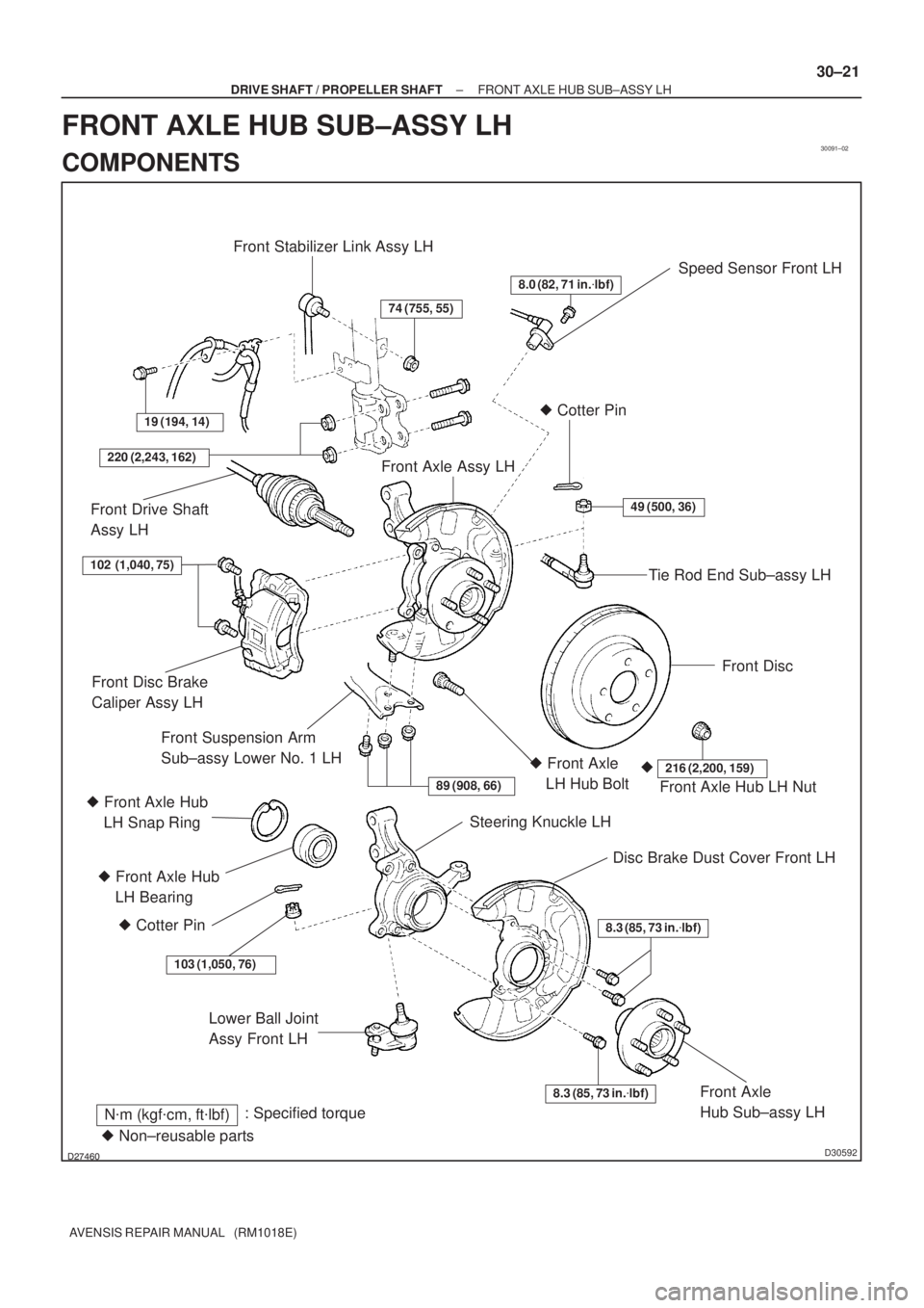
30091±02
������D30592
Speed Sensor Front LH
Lower Ball Joint
Assy Front LH
N�m (kgf�cm, ft�lbf): Specified torque
8.0 (82, 71 in.�lbf)
49 (500, 36)
Tie Rod End Sub±assy LH � Cotter Pin
Front Disc
Front Axle Assy LH
19 (194, 14)
Front Stabilizer Link Assy LH
74 (755, 55)
220 (2,243, 162)
Front Drive Shaft
Assy LH
Front Axle Hub LH Nut
216 (2,200, 159)�� Front Axle
LH Hub Bolt
89 (908, 66)
Steering Knuckle LH
Disc Brake Dust Cover Front LH
8.3 (85, 73 in.�lbf)
8.3 (85, 73 in.�lbf)Front Axle
Hub Sub±assy LH
Front Disc Brake
Caliper Assy LH
Front Suspension Arm
Sub±assy Lower No. 1 LH
� Front Axle Hub
LH Bearing
� Cotter Pin
103 (1,050, 76)
102 (1,040, 75)
� Non±reusable parts � Front Axle Hub
LH Snap Ring
± DRIVE SHAFT / PROPELLER SHAFTFRONT AXLE HUB SUB±ASSY LH
30±21
AVENSIS REPAIR MANUAL (RM1018E)
FRONT AXLE HUB SUB±ASSY LH
COMPONENTS
Page 191 of 1690

REPLACEMENT
HINT:
Replace the RH side by the same")
300JY±01
������F45751
SST
C80291
F44775
C67088
30±22
±
DRIVE SHAFT / PROPELLER SHAFT FRONT AXLE HUB SUB±ASSY LH
AVENSIS REPAIR MANUAL (RM1018E)
REPLACEMENT
HINT:
Replace the RH side by the same procedures as the LH side.
1. REMOVE FRONT WHEEL
2.SEPARATE FRONT STABILIZER LINK ASSY LH (See page 30±6) 3. REMOVE FRONT AXLE HUB LH NUT
(a) Using SST and a hammer, unstake the staked part of theaxle hub LH nut.
SST 09930±00010
(b) While applying the brakes, remove the axle hub LH nut.
4. DISCONNECT SPEED SENSOR FRONT LH
(a) Remove the bolt, and disconnect the speed sensor wire and flexible hose from the shock absorber.
(b) Remove the bolt, separate the speed sensor front LH from the steering knuckle.
NOTICE:
�Be careful not to damage the speed sensor.
�Prevent foreign matter from attaching to the speed
sensor.
5. SEPARATE FRONT DISC BRAKE CALIPER ASSY LH
(a) Removing the 2 bolts, separate the disc brake caliper assy LH from the steering knuckle.
NOTICE:
Use a string or other device to keep the brake caliper from
hanging down.
Page 192 of 1690
F40217
SSTTurn
Hold
C80293
D27403
C83023
± DRIVE SHAFT / PROPELLER SHAFTFRONT AXLE HUB SUB±ASSY LH
30±23
AVENSIS REPAIR MANUAL (RM1018E)
6. REMOVE FRONT DISC
7. SEPARATE TIE ROD END SUB±ASSY LH
(a) Remove the cotter pin and nut.
(b) Using SST, separate the tie rod end sub±assy LH from the
steering knuckle.
SST 09628±62011
8. SEPARATE FRONT SUSPENSION ARM SUB±ASSY
LOWER NO.1 LH
(a) Remove the bolt and 2 nuts, and separate the suspension
arm sub±assy lower No.1 LH from the lower ball joint.
9. REMOVE FRONT AXLE ASSY LH
(a) Using a plastic hammer, separate the drive shaft assy LH
from the axle hub.
NOTICE:
Be careful not to damage the boot and ABS speed sensor
rotor.
(b) Remove the 2 bolts, nuts and steering knuckle with the
shock absorber.

16±21
AVENSIS REPAIR MANUAL (RM1018E)
WATER PUMP ASSY(1AZ±FE)
REPLACEMENT
1.DRAIN COOLANT (See page 16±19)
2. REM")

16±33
AVENSIS REPAIR MANUAL (RM1018E)
WATER PUMP ASSY(1AZ±FSE)
REPLACEMENT
1.DRAIN COOLANT (See page 16±31)
2. R")

6. REMOVE FRONT DISC
7. SEPARATE TIE ROD END SUB±ASSY LH")