Page 1408 of 1690

TORQUE SPECIFICATION
Part TightenedN�mkgf�cmft�lbf
Steering intermediate shaft assy No. 2 x Oil pressure pow")
031FZ±01
03±58
± SERVICE SPECIFICATIONSSTEERING COLUMN
AVENSIS REPAIR MANUAL (RM1018E)
TORQUE SPECIFICATION
Part TightenedN�mkgf�cmft�lbf
Steering intermediate shaft assy No. 2 x Oil pressure power steering
column assy (LHD steering positoin type)2828621
Steering sliding yoke sub±assy x Oil pressure power steering column assy
(RHD steering positoin type)2828621
Steering intermediate shaft assy No. 2 x Electric power steering column
assy (LHD steering positoin type)3536026
Steering sliding yoke sub±assy x Electric power steering column assy
(RHD steering positoin type)3536026
Steering sliding yoke sub±assy x Steering intermediate shaft assy No. 23536026
Steering column assy set bolt2121415
Steering sliding yoke sub±assy x Steering gear assy
(LHD steering positoin type)3536026
Steering intermediate shaft assy No. 2 x Steering gear assy
(RHD steering positoin type)3536026
Steering wheel set nut5051037
Steering wheel pad set screw (Torx screw)8.89078 in.´lbf
Steering column cover LWR x Steering column assy5.05144 in.´lbf
Instrument panel airbag assy1818413
Power steering ECU assy (Bolt A)88271 in.´lbf
Power steering ECU assy (Bolt B)15.515811
Page 1409 of 1690
031HM±01
± SERVICE SPECIFICATIONSSUPPLEMENTAL RESTRAINT SYSTEM
03±63
AVENSIS REPAIR MANUAL (RM1018E)
SUPPLEMENTAL RESTRAINT SYSTEM
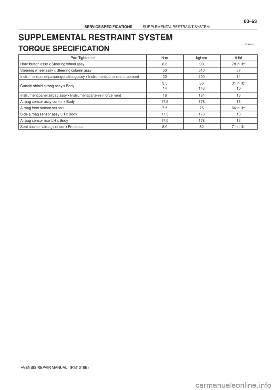
TORQUE SPECIFICATION
Part TightenedN�mkgf�cmft�lbf
Horn button assy x Steering wheel assy8.89078 in.�lbf
Steering wheel assy x Steering column assy5051037
Instrument panel passenger airbag assy x Instrument panel reinforcement2020014
Curtain shield airbag assy x Body3.53631 in.�lbfCurtain shield airbag assy x Body3.5
14
36
143
31 in.lbf
10
Instrument panel airbag assy x Instrument panel reinforcement1818413
Airbag sensor assy center x Body17.517813
Airbag front sensor set bolt7.57666 in.�lbf
Side airbag sensor assy LH x Body17.517813
Airbag sensor rear LH x Body17.517813
Seat position airbag sensor x Front seat8.08271 in.�lbf
Page 1443 of 1690

19±29
AVENSIS REPAIR MANUAL (RM1018E)
GENERATOR ASSY(1CD±FTV)
REPLACEMENT
1.REMOVE FRONT WHEEL RH
2.REMOVE RADIATOR SUPPORT OPENING")
190O1±01
A79176
±
STARTING & CHARGING GENERATOR ASSY(1CD±FTV)
19±29
AVENSIS REPAIR MANUAL (RM1018E)
GENERATOR ASSY(1CD±FTV)
REPLACEMENT
1.REMOVE FRONT WHEEL RH
2.REMOVE RADIATOR SUPPORT OPENING COVER
3.REMOVE ENGINE ROOM COVER SIDE
4.REMOVE ENGINE UNDER COVER SUB±ASSY NO.1
5.REMOVE ENGINE UNDER COVER RH
6.REMOVE V (COOLER COMPRESSOR TO CRANKSHAFT PULLEY) BELT NO.1
(See page 14±269)
7.REMOVE GENERATOR V BELT (See page 14±269)
8.REMOVE FLOOR PANEL BRACE FRONT(See page 15±10)
9.REMOVE EXHAUST PIPE ASSY FRONT(See page 15±10)
10.REMOVE EXHAUST PIPE ASSY (W/ COLD AREA) (See page 13±11)
11.REMOVE GENERATOR ASSY
(a)Remove the bolt and disconnect the wire harness.
(b)Remove the cap and nut, disconnect the generator wire.
(c)Disconnect the generator connector.
(d)Remove the 2 bolts and the generator.
12.INSTALL GENERATOR ASSY Torque:
31 N�m (320 kgf �cm, 23 ft �lbf) for M8
47 N �m (475 kgf �cm, 34 ft �lbf) for M10
9.8 N �m (100 kgf �cm, 7 ft �lbf) for Generator wire
5.0 N �m (51 kgf �cm, 44 ft �lbf) for Wire harness
13.INSTALL EXHAUST PIPE ASSY (W/ COLD AREA) (See page 13±11)
14.INSTALL EXHAUST PIPE ASSY FRONT(See page 15±10)
15.INSTALL FLOOR PANEL BRACE FRONT(See page 15±10)
16. ADJUST V (COOLER COMPRESSOR TO CRANKSHAFT PULLEY) BELT NO.1 (See page 14±286)
17. INSTALL FRONT WHEEL RH Torque: 103 N �m (1,050 kgf �cm, 76 ft �lbf)
18. CHECK FOR EXHAUST GAS LEAKS
Page 1464 of 1690

5006X−01
Steering
Column
Protector No.1
F44781
Horn Button Assy
Steering Wheel Assy
Spiral Cable Sub −Assy
Steering Column Cover
Headlamp Dimmer Switch AssySteering Column Assy
Steering
Sliding Yoke
Sub− Assy
Steering Intermediate
Shaft Assy No.2
Column Hole Cover Silencer Sheet
Steering Column Cover LWR
Windshield Wiper
Switch Assy
N
�m (kgf �cm, ft�lbf): Specified torque
OIL Pressure Power Steering:
Steering Intermediate
Shaft Assy No.2
Steering
Sliding Yoke
Sub−Assy
35 (360, 26)
Column Hole Cover
Silencer Sheet
LHD Steering Position Type:
LHD Steering Position
Type: w/ Instrument Cluster
Finish Panel Assy
Floor Shift
Parking Lock Cable
Assy (A/T Transaxle)
Instrument Panel
Hole Cover
5 (51, 44 in.�
�� � lbf)
18 (184, 13)
18 (184, 13)
Instrument Panel
Airbag Assy
18 (184, 13)
18 (184, 13)
18 (184, 13)
25 (255, 18)
50 (510, 37)
35 (360, 26)
35 (360, 26)
28 (286, 21)
35 (360, 26)
28 (286, 21)
25 (255, 18)
25 (255, 18)
−
STEERING COLUMN STEERING COLUMN ASSY
50−5
STEERING COLUMN ASSY
COMPONENTS
Page 1466 of 1690
F44779
Horn Button Assy
Steering Wheel Assy
Headlamp Dimmer Switcn Assy
Spiral Cable
Windshield Wiper Switch Steering Column Cover
Steering Column Assy
Steering
Intermediate
Shaft Assy
No.2
Steering Sliding
Yoke sub−assy
Column Hole Cover Silencer Sheet
N �m (kgf �cm, ft�lbf): Specified torque Steering Sliding
Yoke sub
−assy
Steering Intermediate
Shaft Assy No.2
LHD Steering Position Type:
Electric Power Steering:
35 (360, 26)
35 (360, 26)
35 (360, 26)
Column Hole Cover Silencer Sheet
Steering Column Cover
LW R
Floor Shift Parking Lock
Cable Assy (A/T Transaxle)
Instrument Panel Airbag Assy
18 (184, 13)
Steering
Column
Protector
No.1
Instrument
Panel
Hole Cover
18 (184, 13)
18 (184, 13)
5 (51, 44 in. �
�� � lbf)
25 (255, 18)
18 (184, 13)
18 (184, 13)
LHD Steering Position Type: w/ Instrument Cluster
Finish Panel Assy
50 (510, 37)
25 (255, 18)
Steering Column
Protector No.1
35 (360, 26)
M/T Transaxle:25 (255, 18)
−
STEERING COLUMN STEERING COLUMN ASSY
50−7
Page 1478 of 1690

54.INSTALL INSTRUMENT PANEL AIR BAG ASSY (See page 60±54)
55. INSTALL COLUMN")
F44800
Marks
F44801
Torx ScrewScrew Case
±
STEERING COLUMN STEERING COLUMN ASSY
50±19
AVENSIS REPAIR MANUAL (RM1018E)
54.INSTALL INSTRUMENT PANEL AIR BAG ASSY (See page 60±54)
55. INSTALL COLUMN HOLE COVER SILENCER SHEET
56. PLACE FRONT WHEELS FACING STRAIGHT AHEAD
57.INSTALL SPIRAL CABLE SUB±ASSY (See page 60±26)
58. CENTER SPIRAL CABLE
(a) Check that the front wheels are facing straight ahead.
(b) Turn the cable counterclockwise by hand until it becomesharder to turn.
(c) Then rotate the cable clockwise about 2.5 turns to align the marks.
HINT:
The cable will rotate about 2.5 turns to either left or right of the
center.
59. INSTALL STEERING WHEEL ASSY
(a) Align matchmarks on the steering wheel and main shaft assembly.
(b) Install the steering wheel set nut. Torque: 50 N´m (510 kgf´cm, 37 ft´lbf)
(c) Connect the connector.
60. INSTALL HORN BUTTON ASSY
NOTICE:
�Never use airbag parts from another vehicle. When
replacing parts, replace with new ones.
�Make sure the horn button assy is installed with the
specified torque.
�If the horn button assy has been dropped, or there are
cracks, dents or other defects in the case or connec-
tor, replace the horn button assy with a new one.
�When installing the horn button assy, take care that
the wirings do not interfere with other parts and that
they are not pinched between other parts.
(a) Connect the terminal.
(b) Connect the airbag connector.
(c) Install the steering horn button assy after confirming that the circumference groove of the torx screws is caught on
the screw case.
(d) Using a torx socket wrench, torque the 2 screws. Torque: 8.8 N´m (90 kgf´cm, 78 in.´lbf)
61. STEERING WHEEL CENTER POINT
62. CONNECT BATTERY NEGATIVE TERMINAL
63.INSPECT SRS WARNING LIGHT(See page 05±1184)
64. PERFORM CALIBRATION OF TORQUE SENSOR ZERO POINT (ELECTRIC POWER STEERING) (See page 05±1045)
Page 1479 of 1690

STEERING SYSTEM
PRECAUTION
1. HANDLING PRECAUTIONS ON STEERING SYSTEM
(a) Be careful to replace the parts properly")
5000C±14
±
STEERING COLUMN STEERING SYSTEM
50±1
AVENSIS REPAIR MANUAL (RM1018E)
STEERING SYSTEM
PRECAUTION
1. HANDLING PRECAUTIONS ON STEERING SYSTEM
(a) Be careful to replace the parts properly because they could affect the performance of the steering sys-
tem and result in a driving hazard.
2. HANDLING PRECAUTIONS ON SRS AIRBAG SYSTEM
(a) The vehicle is equipped with SRS (Supplemental Restraint System) such as \
the driver airbag and front passenger airbag. Failure to carry out service operation in the correct sequence \
could cause the SRS
to unexpectedly deploy during servicing, possibly leading to a serious acc\
ident. Before servicing (in-
cluding removal or installation of parts, inspection or replacement), be sure \
to read the precautionary
notices in the supplemental restraint system (See page 60±1).
3. HANDLING PRECAUTIONS ON STEERING COLUMN
(a) Do not give an impact to the steering column assy, especially the motor and the torque sensor. If a great impact is given (dropping it to the floor, etc.), replace it with a new one.
(b) When removing the steering column assy, do not pull the harness.
(c) When having replaced the steering column assy and/or the ECU, calibrate the \
zero point of the steer- ing torque sensor.
(d) In the case of disconnecting a connector related to the power steering sys\
tem, turn the ignition switch ON, set the steering wheel in the straight±ahead position and turn th\
e ignition switch OFF before dis-
connecting the connector.
(e) In the case of connecting a connector related to the power steering system, make sure that the ignit\
ion switch is OFF at first. After connecting the connector, set the steering wheel assy in the straight±ahead
position, and then turn the ignition switch ON.
NOTICE:
Never turn on the ignition switch when the steering wheel assy is set in orde\
r than the straight±ahead
position.
(f) If the above operation is not done, the zero point of the steering torque \
sensor is shifted away from the proper position, making difference in the steering effort between right and left. If this happens, per-
form the zero point calibration of the steering torque sensor (See page 05±1042).
Page 1506 of 1690
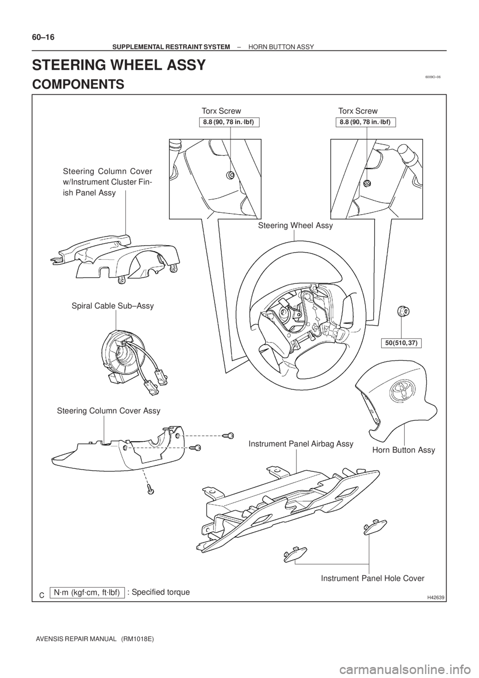
6009O±06
H42639N�m (kgf�cm, ft�lbf): Specified torqueTorx Screw
Steering Column Cover
w/Instrument Cluster Fin-
ish Panel Assy
Torx Screw
Horn Button Assy Steering Column Cover AssySpiral Cable Sub±Assy
Steering Wheel Assy
50 (510, 37)
Instrument Panel Airbag Assy
Instrument Panel Hole Cover
8.8 (90, 78 in.�lbf)8.8 (90, 78 in.�lbf)
60±16
± SUPPLEMENTAL RESTRAINT SYSTEMHORN BUTTON ASSY
AVENSIS REPAIR MANUAL (RM1018E)
STEERING WHEEL ASSY
COMPONENTS